
Architecture of Complex Systems Week 1: Systems
MY
Published · 31 slides · 0 views

1 / 1

Description
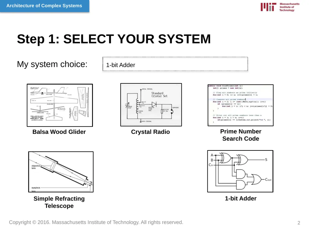
Architecture of Complex Systems Week 1: Systems Thinking Name John Doe Project Portfolio 1 Step 1: SELECT YOUR SYSTEM My system choice: 1-bit Adder Balsa Wood Glider Crystal Radio Prime Number Search Code Simple Refracting Telescope 1-bit
Related Topics
Share
Embed code
Download this presentation From Below
"Architecture of Complex Systems Week 1: Systems" is the property of its rightful owner. Permission is granted to download and print the materials on this website for personal, non-commercial use only, and to display it on your personal computer provided you do not modify the materials and that you retain all copyright notices contained in the materials. By downloading content from our website, you accept the terms of this agreement.
Presentation Transcript
01
Architecture of Complex Systems
Week 1: Systems Thinking Name John Doe Project Portfolio 1<br>
Week 1: Systems Thinking Name John Doe Project Portfolio 1<br>
02
Step 1: SELECT YOUR SYSTEM My system choice: 1-bit Adder Balsa Wood Glider Crystal Radio Prime Number Search Code Simple Refracting Telescope 1-bit Adder 2<br>
03
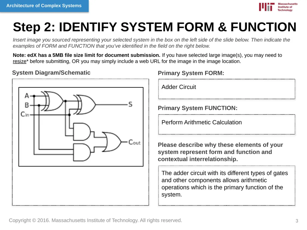
Step 2: IDENTIFY SYSTEM FORM & FUNCTION Primary System FORM: System Diagram/Schematic Insert image you sourced representing your selected system in the box on the left side of the slide below. Then indicate the examples of FORM and FUNCTION that you’ve identified in the field on the right below.
Note: edX has a 5MB file size limit for document submission. If you have selected large image(s), you may need to resize* before submitting, OR you may simply include a web URL for the image in the image location. Primary System FUNCTION: Please describe why these elements of your system represent form and function and contextual interrelationship. Adder Circuit Perform Arithmetic Calculation The adder circuit with its different types of gates and other components allows arithmetic operations which is the primary function of the system. 3<br>
Note: edX has a 5MB file size limit for document submission. If you have selected large image(s), you may need to resize* before submitting, OR you may simply include a web URL for the image in the image location. Primary System FUNCTION: Please describe why these elements of your system represent form and function and contextual interrelationship. Adder Circuit Perform Arithmetic Calculation The adder circuit with its different types of gates and other components allows arithmetic operations which is the primary function of the system. 3<br>
04
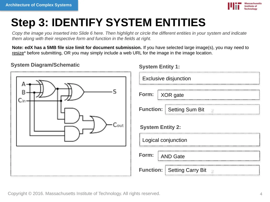
Step 3: IDENTIFY SYSTEM ENTITIES System Entity 1: System Diagram/Schematic z Copy the image you inserted into Slide 6 here. Then highlight or circle the different entities in your system and indicate them along with their respective form and function in the fields at right.
Note: edX has a 5MB file size limit for document submission. If you have selected large image(s), you may need to resize* before submitting, OR you may simply include a web URL for the image in the image location. Form: Function: System Entity 2: Form: Function: Exclusive disjunction XOR gate Setting Sum Bit Logical conjunction AND Gate Setting Carry Bit z 4<br>
Note: edX has a 5MB file size limit for document submission. If you have selected large image(s), you may need to resize* before submitting, OR you may simply include a web URL for the image in the image location. Form: Function: System Entity 2: Form: Function: Exclusive disjunction XOR gate Setting Sum Bit Logical conjunction AND Gate Setting Carry Bit z 4<br>
05
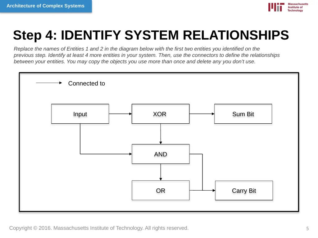
Step 4: IDENTIFY SYSTEM RELATIONSHIPS XOR AND OR Carry Bit Sum Bit Input Replace the names of Entities 1 and 2 in the diagram below with the first two entities you identified on the previous step. Identify at least 4 more entities in your system. Then, use the connectors to define the relationships between your entities. You may copy the objects you use more than once and delete any you don’t use. 5 Connected to<br>
06
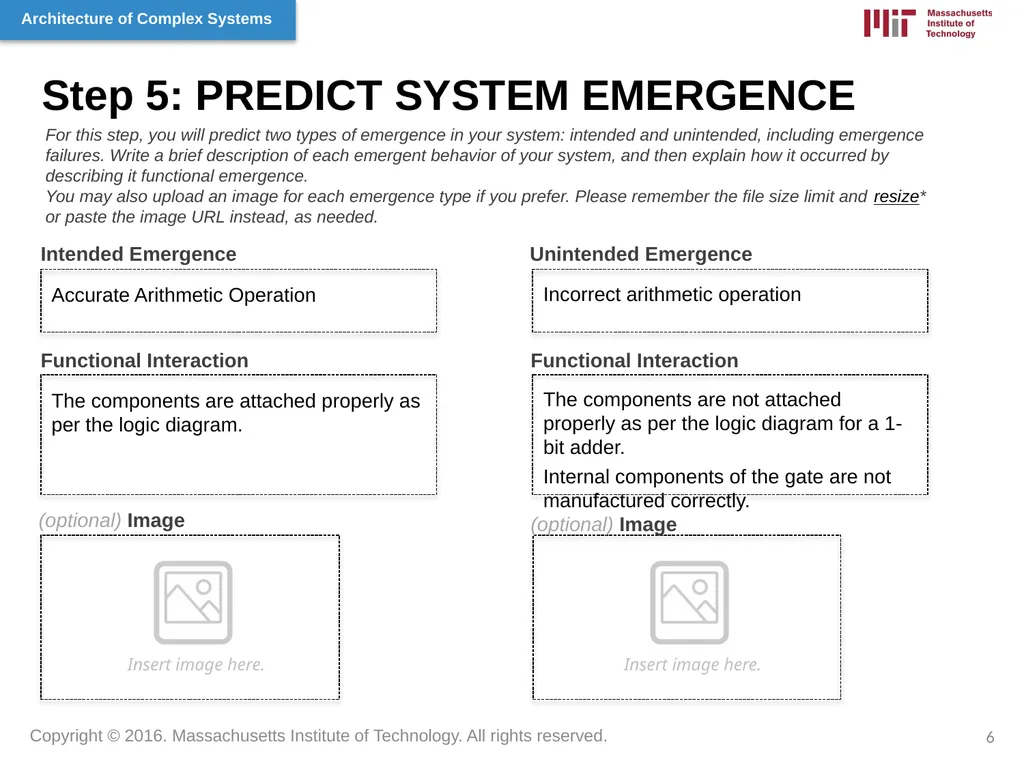
Step 5: PREDICT SYSTEM EMERGENCE Intended Emergence Unintended Emergence Functional Interaction (optional) Image Functional Interaction (optional) Image For this step, you will predict two types of emergence in your system: intended and unintended, including emergence failures. Write a brief description of each emergent behavior of your system, and then explain how it occurred by describing it functional emergence.
You may also upload an image for each emergence type if you prefer. Please remember the file size limit and resize* or paste the image URL instead, as needed. Insert image here. Insert image here. Accurate Arithmetic Operation Incorrect arithmetic operation The components are attached properly as per the logic diagram. The components are not attached properly as per the logic diagram for a 1-bit adder.
Internal components of the gate are not manufactured correctly. 6<br>
You may also upload an image for each emergence type if you prefer. Please remember the file size limit and resize* or paste the image URL instead, as needed. Insert image here. Insert image here. Accurate Arithmetic Operation Incorrect arithmetic operation The components are attached properly as per the logic diagram. The components are not attached properly as per the logic diagram for a 1-bit adder.
Internal components of the gate are not manufactured correctly. 6<br>
07
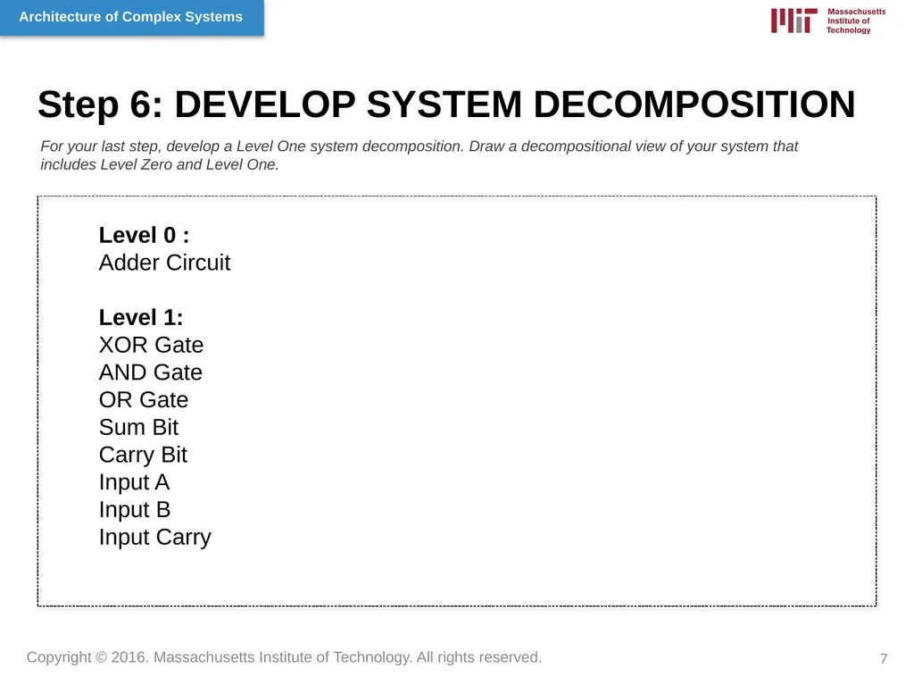
Step 6: DEVELOP SYSTEM DECOMPOSITION For your last step, develop a Level One system decomposition. Draw a decompositional view of your system that includes Level Zero and Level One. 7 Level 0 :
Adder Circuit
Level 1:
XOR Gate
AND Gate
OR Gate
Sum Bit
Carry Bit
Input A
Input B
Input Carry<br>
Adder Circuit
Level 1:
XOR Gate
AND Gate
OR Gate
Sum Bit
Carry Bit
Input A
Input B
Input Carry<br>
08
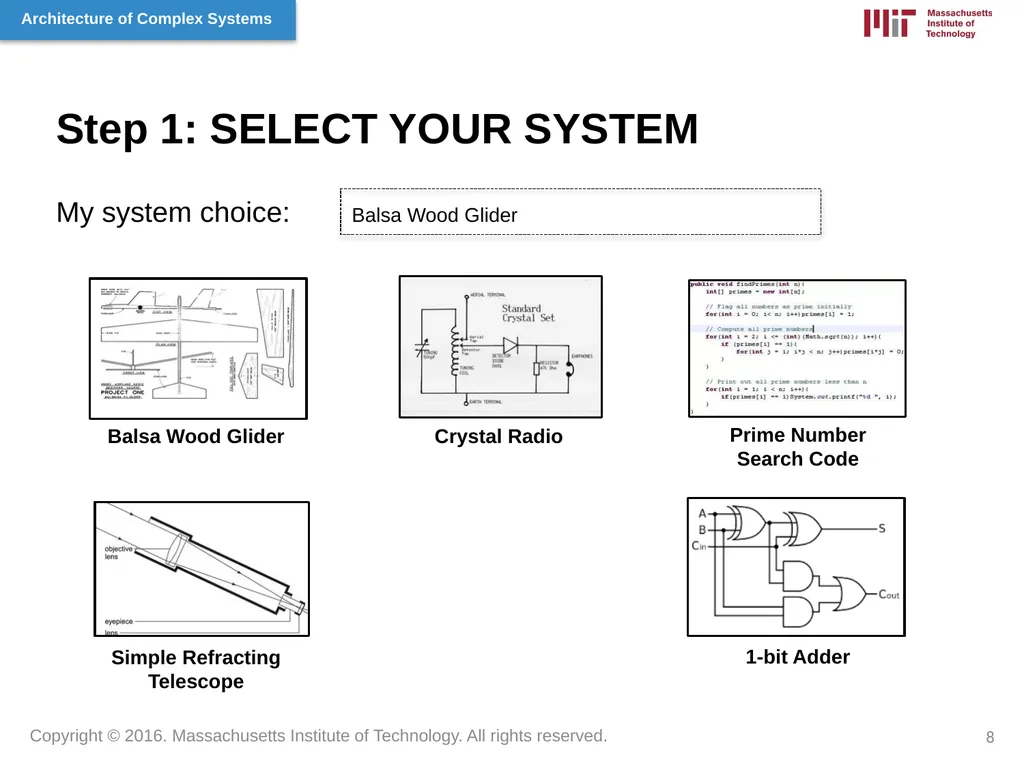
Step 1: SELECT YOUR SYSTEM My system choice: Balsa Wood Glider Balsa Wood Glider Crystal Radio Prime Number Search Code Simple Refracting Telescope 1-bit Adder 8<br>
09
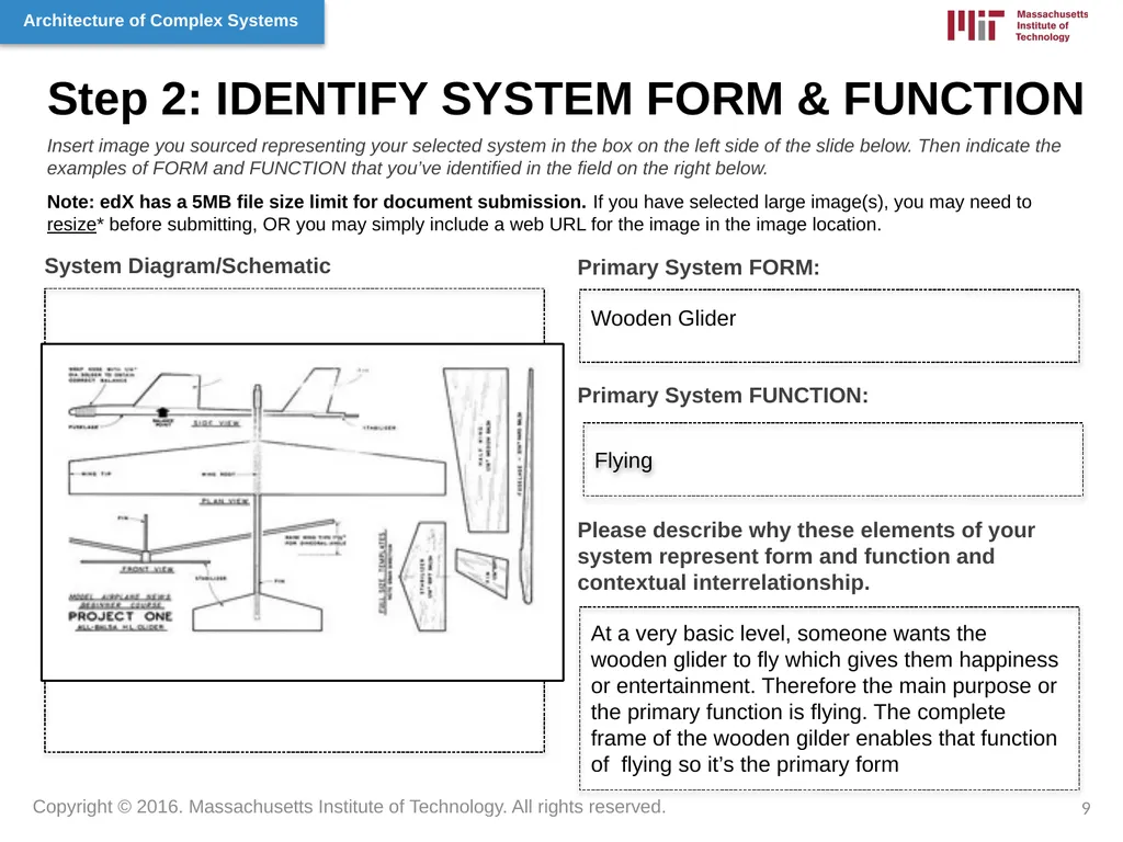
Step 2: IDENTIFY SYSTEM FORM & FUNCTION Primary System FORM: Flying System Diagram/Schematic Insert image you sourced representing your selected system in the box on the left side of the slide below. Then indicate the examples of FORM and FUNCTION that you’ve identified in the field on the right below.
Note: edX has a 5MB file size limit for document submission. If you have selected large image(s), you may need to resize* before submitting, OR you may simply include a web URL for the image in the image location. Insert image here. Primary System FUNCTION: Please describe why these elements of your system represent form and function and contextual interrelationship. Wooden Glider At a very basic level, someone wants the wooden glider to fly which gives them happiness or entertainment. Therefore the main purpose or the primary function is flying. The complete frame of the wooden gilder enables that function of flying so it’s the primary form 9<br>
Note: edX has a 5MB file size limit for document submission. If you have selected large image(s), you may need to resize* before submitting, OR you may simply include a web URL for the image in the image location. Insert image here. Primary System FUNCTION: Please describe why these elements of your system represent form and function and contextual interrelationship. Wooden Glider At a very basic level, someone wants the wooden glider to fly which gives them happiness or entertainment. Therefore the main purpose or the primary function is flying. The complete frame of the wooden gilder enables that function of flying so it’s the primary form 9<br>
10
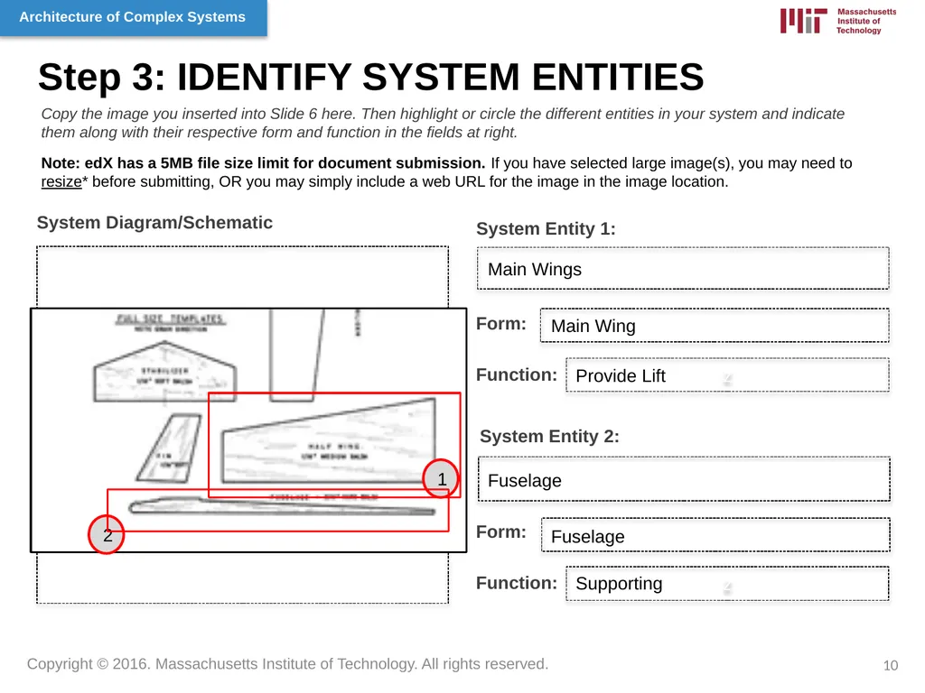
Step 3: IDENTIFY SYSTEM ENTITIES System Entity 1: System Diagram/Schematic z Copy the image you inserted into Slide 6 here. Then highlight or circle the different entities in your system and indicate them along with their respective form and function in the fields at right.
Note: edX has a 5MB file size limit for document submission. If you have selected large image(s), you may need to resize* before submitting, OR you may simply include a web URL for the image in the image location. Form: Function: System Entity 2: Form: Function: Main Wings Main Wing Provide Lift Fuselage Fuselage Supporting z 10 1 2<br>
Note: edX has a 5MB file size limit for document submission. If you have selected large image(s), you may need to resize* before submitting, OR you may simply include a web URL for the image in the image location. Form: Function: System Entity 2: Form: Function: Main Wings Main Wing Provide Lift Fuselage Fuselage Supporting z 10 1 2<br>
11
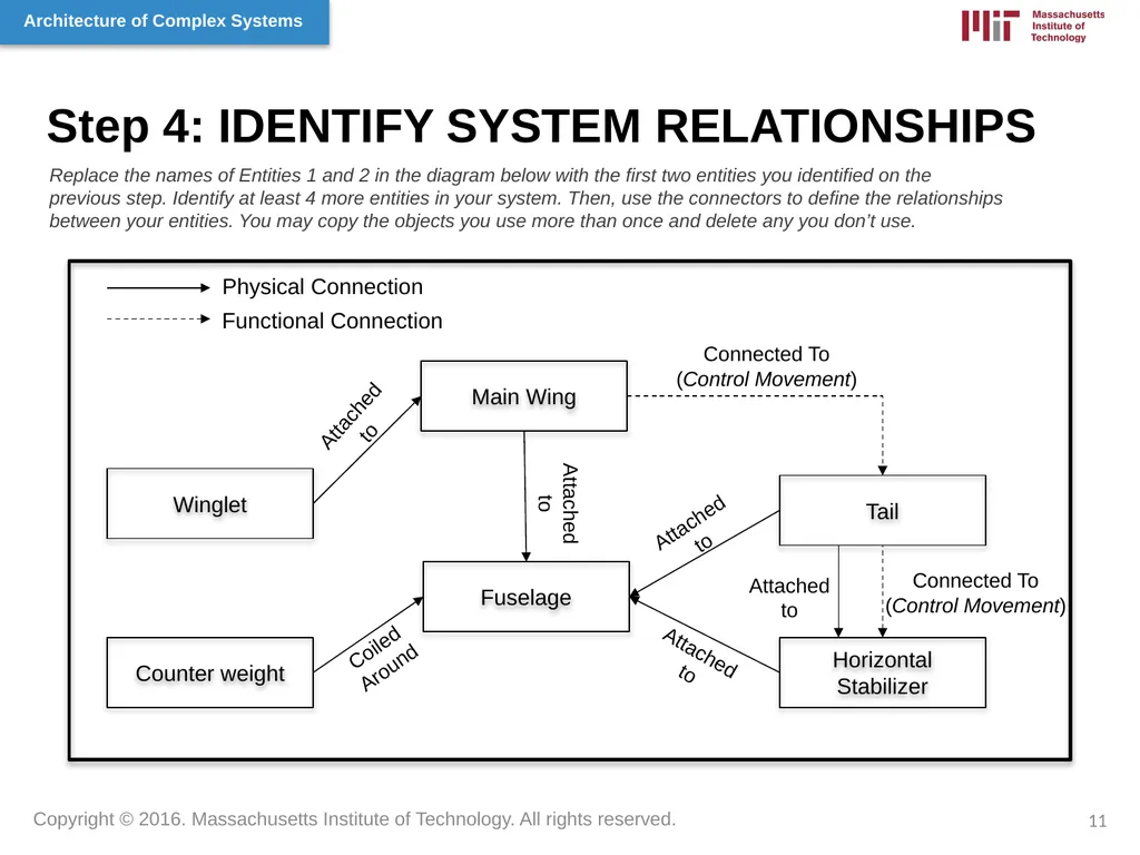
Step 4: IDENTIFY SYSTEM RELATIONSHIPS Main Wing Fuselage Horizontal Stabilizer Tail Counter weight Winglet Replace the names of Entities 1 and 2 in the diagram below with the first two entities you identified on the previous step. Identify at least 4 more entities in your system. Then, use the connectors to define the relationships between your entities. You may copy the objects you use more than once and delete any you don’t use. 11 Attached to Attached to Attached to Connected To
(Control Movement) Coiled Around Attached to Attached to Physical Connection Functional Connection Connected To
(Control Movement)<br>
(Control Movement) Coiled Around Attached to Attached to Physical Connection Functional Connection Connected To
(Control Movement)<br>
12
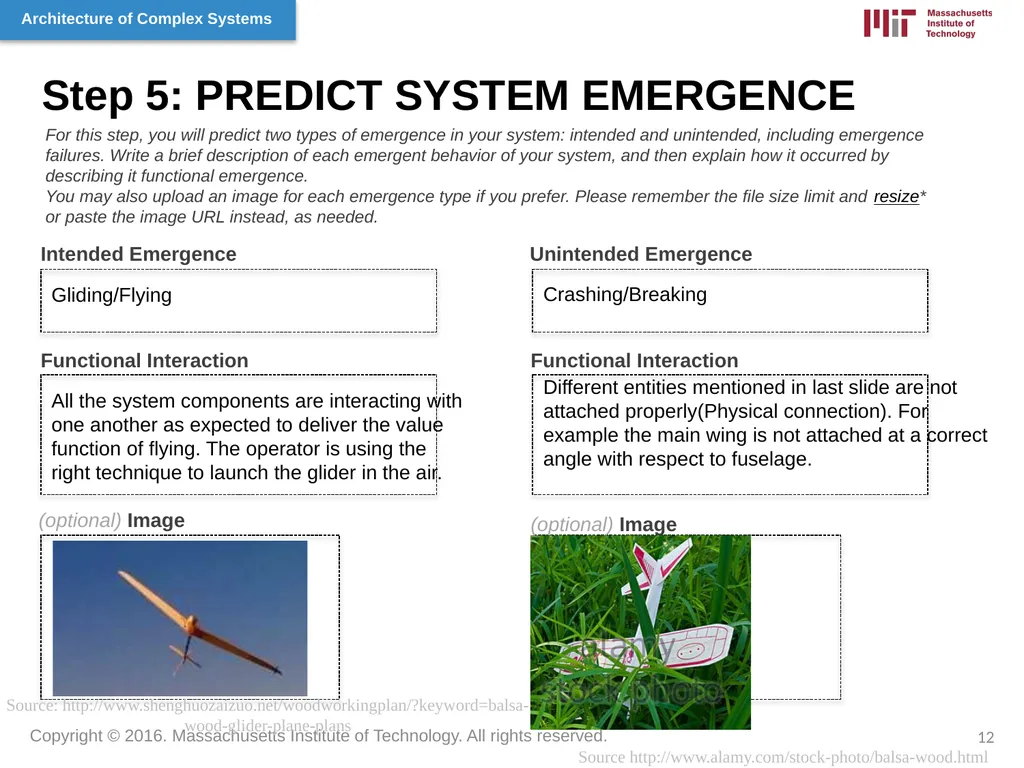
Step 5: PREDICT SYSTEM EMERGENCE Intended Emergence Unintended Emergence Functional Interaction (optional) Image Functional Interaction (optional) Image For this step, you will predict two types of emergence in your system: intended and unintended, including emergence failures. Write a brief description of each emergent behavior of your system, and then explain how it occurred by describing it functional emergence.
You may also upload an image for each emergence type if you prefer. Please remember the file size limit and resize* or paste the image URL instead, as needed. Insert image here. Source http://www.alamy.com/stock-photo/balsa-wood.html Gliding/Flying Crashing/Breaking All the system components are interacting with one another as expected to deliver the value function of flying. The operator is using the right technique to launch the glider in the air. Different entities mentioned in last slide are not attached properly(Physical connection). For example the main wing is not attached at a correct angle with respect to fuselage. 12 Source: http://www.shenghuozaizuo.net/woodworkingplan/?keyword=balsa-wood-glider-plane-plans<br>
You may also upload an image for each emergence type if you prefer. Please remember the file size limit and resize* or paste the image URL instead, as needed. Insert image here. Source http://www.alamy.com/stock-photo/balsa-wood.html Gliding/Flying Crashing/Breaking All the system components are interacting with one another as expected to deliver the value function of flying. The operator is using the right technique to launch the glider in the air. Different entities mentioned in last slide are not attached properly(Physical connection). For example the main wing is not attached at a correct angle with respect to fuselage. 12 Source: http://www.shenghuozaizuo.net/woodworkingplan/?keyword=balsa-wood-glider-plane-plans<br>
13
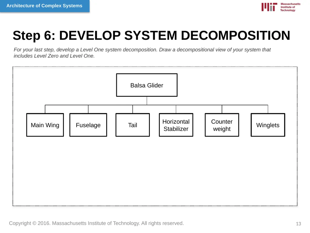
Step 6: DEVELOP SYSTEM DECOMPOSITION For your last step, develop a Level One system decomposition. Draw a decompositional view of your system that includes Level Zero and Level One. 13 Balsa Glider Main Wing Fuselage Tail Horizontal Stabilizer Counter weight Winglets<br>
14
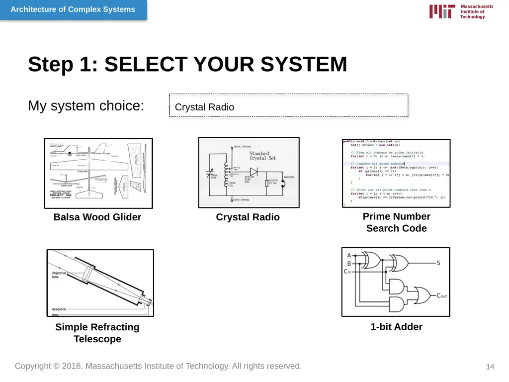
Step 1: SELECT YOUR SYSTEM My system choice: Crystal Radio Balsa Wood Glider Crystal Radio Prime Number Search Code Simple Refracting Telescope 1-bit Adder 14<br>
15
Step 2: IDENTIFY SYSTEM FORM & FUNCTION Primary System FORM: System Diagram/Schematic Insert image you sourced representing your selected system in the box on the left side of the slide below. Then indicate the examples of FORM and FUNCTION that you’ve identified in the field on the right below.
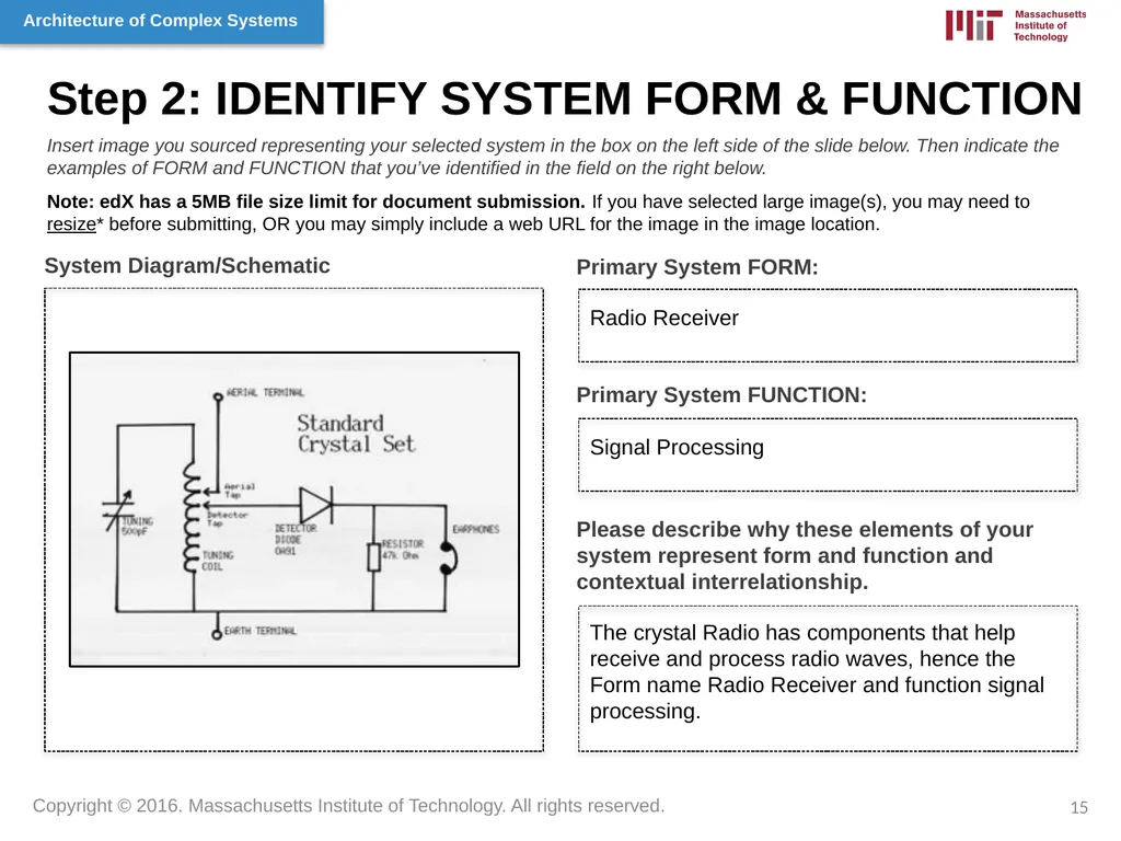
Note: edX has a 5MB file size limit for document submission. If you have selected large image(s), you may need to resize* before submitting, OR you may simply include a web URL for the image in the image location. Primary System FUNCTION: Please describe why these elements of your system represent form and function and contextual interrelationship. Radio Receiver Signal Processing The crystal Radio has components that help receive and process radio waves, hence the Form name Radio Receiver and function signal processing. 15<br>
Note: edX has a 5MB file size limit for document submission. If you have selected large image(s), you may need to resize* before submitting, OR you may simply include a web URL for the image in the image location. Primary System FUNCTION: Please describe why these elements of your system represent form and function and contextual interrelationship. Radio Receiver Signal Processing The crystal Radio has components that help receive and process radio waves, hence the Form name Radio Receiver and function signal processing. 15<br>
16
Step 3: IDENTIFY SYSTEM ENTITIES System Entity 1: System Diagram/Schematic z Copy the image you inserted into Slide 6 here. Then highlight or circle the different entities in your system and indicate them along with their respective form and function in the fields at right.
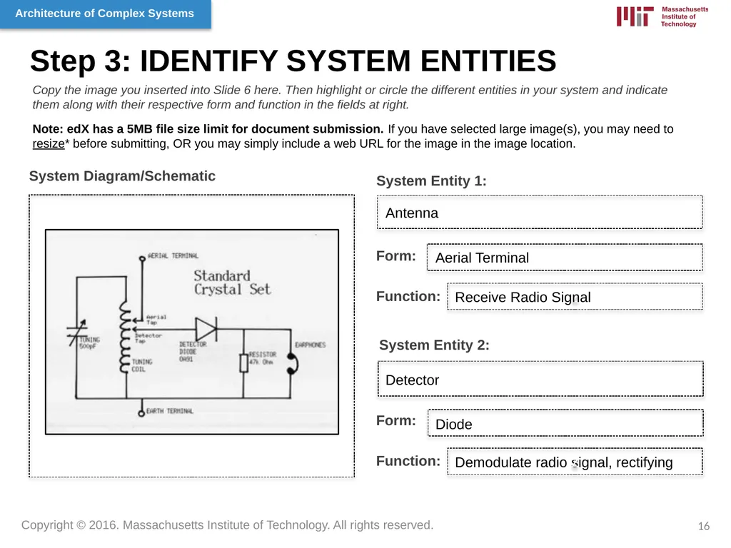
Note: edX has a 5MB file size limit for document submission. If you have selected large image(s), you may need to resize* before submitting, OR you may simply include a web URL for the image in the image location. Form: Function: System Entity 2: Form: Function: Antenna Aerial Terminal Receive Radio Signal Detector Diode Demodulate radio signal, rectifying z 16<br>
Note: edX has a 5MB file size limit for document submission. If you have selected large image(s), you may need to resize* before submitting, OR you may simply include a web URL for the image in the image location. Form: Function: System Entity 2: Form: Function: Antenna Aerial Terminal Receive Radio Signal Detector Diode Demodulate radio signal, rectifying z 16<br>
17
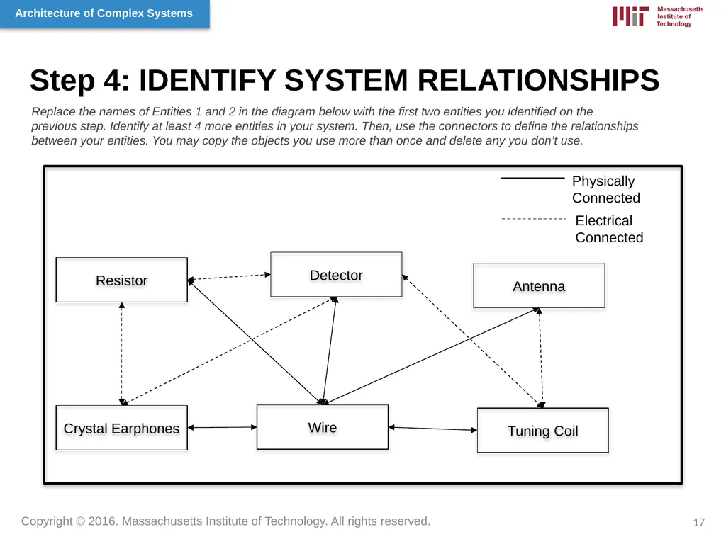
Step 4: IDENTIFY SYSTEM RELATIONSHIPS Antenna Detector Tuning Coil Resistor Crystal Earphones Wire Replace the names of Entities 1 and 2 in the diagram below with the first two entities you identified on the previous step. Identify at least 4 more entities in your system. Then, use the connectors to define the relationships between your entities. You may copy the objects you use more than once and delete any you don’t use. 17 Physically
Connected Electrical
Connected<br>
Connected Electrical
Connected<br>
18
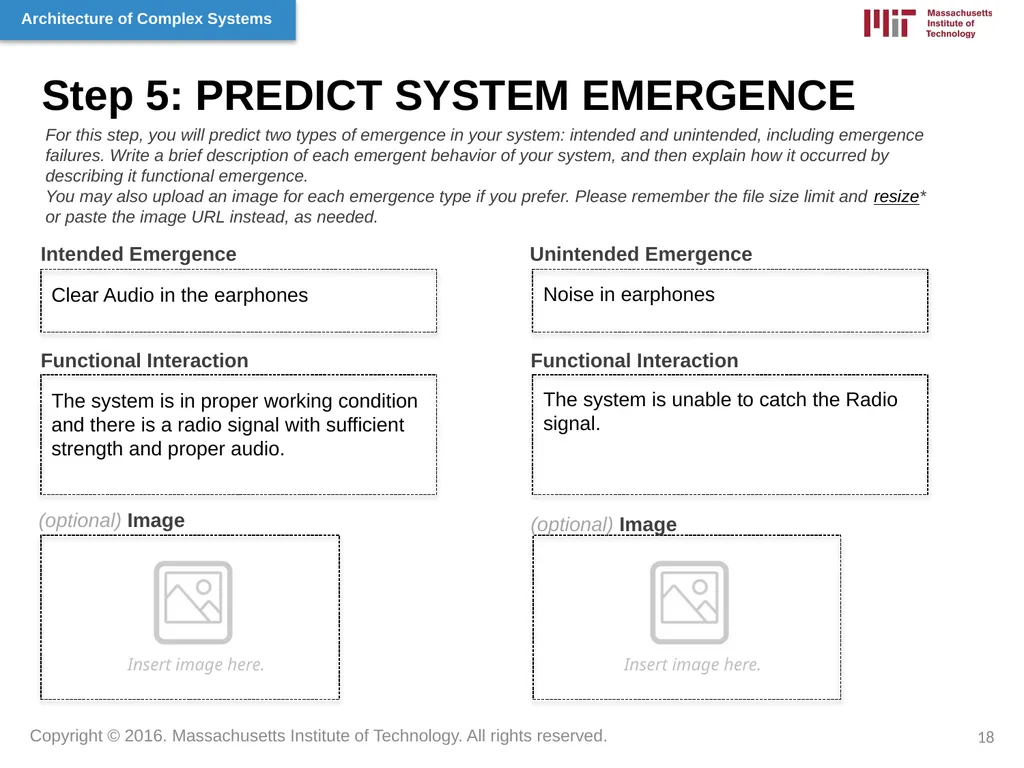
Step 5: PREDICT SYSTEM EMERGENCE Intended Emergence Unintended Emergence Functional Interaction (optional) Image Functional Interaction (optional) Image For this step, you will predict two types of emergence in your system: intended and unintended, including emergence failures. Write a brief description of each emergent behavior of your system, and then explain how it occurred by describing it functional emergence.
You may also upload an image for each emergence type if you prefer. Please remember the file size limit and resize* or paste the image URL instead, as needed. Insert image here. Insert image here. Clear Audio in the earphones Noise in earphones The system is in proper working condition and there is a radio signal with sufficient strength and proper audio. The system is unable to catch the Radio signal. 18<br>
You may also upload an image for each emergence type if you prefer. Please remember the file size limit and resize* or paste the image URL instead, as needed. Insert image here. Insert image here. Clear Audio in the earphones Noise in earphones The system is in proper working condition and there is a radio signal with sufficient strength and proper audio. The system is unable to catch the Radio signal. 18<br>
19
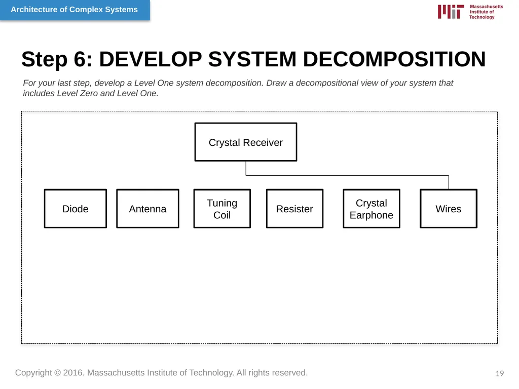
Step 6: DEVELOP SYSTEM DECOMPOSITION For your last step, develop a Level One system decomposition. Draw a decompositional view of your system that includes Level Zero and Level One. 19 Crystal Receiver Diode Antenna Tuning Coil Resister Crystal Earphone Wires<br>
20
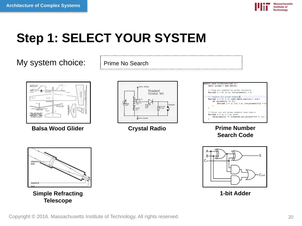
Step 1: SELECT YOUR SYSTEM My system choice: Prime No Search Balsa Wood Glider Crystal Radio Prime Number Search Code Simple Refracting Telescope 1-bit Adder 20<br>
21
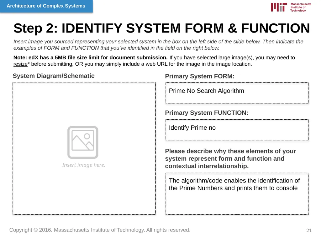
Step 2: IDENTIFY SYSTEM FORM & FUNCTION Primary System FORM: System Diagram/Schematic Insert image you sourced representing your selected system in the box on the left side of the slide below. Then indicate the examples of FORM and FUNCTION that you’ve identified in the field on the right below.
Note: edX has a 5MB file size limit for document submission. If you have selected large image(s), you may need to resize* before submitting, OR you may simply include a web URL for the image in the image location. Insert image here. Primary System FUNCTION: Please describe why these elements of your system represent form and function and contextual interrelationship. Prime No Search Algorithm Identify Prime no The algorithm/code enables the identification of the Prime Numbers and prints them to console 21<br>
Note: edX has a 5MB file size limit for document submission. If you have selected large image(s), you may need to resize* before submitting, OR you may simply include a web URL for the image in the image location. Insert image here. Primary System FUNCTION: Please describe why these elements of your system represent form and function and contextual interrelationship. Prime No Search Algorithm Identify Prime no The algorithm/code enables the identification of the Prime Numbers and prints them to console 21<br>
22
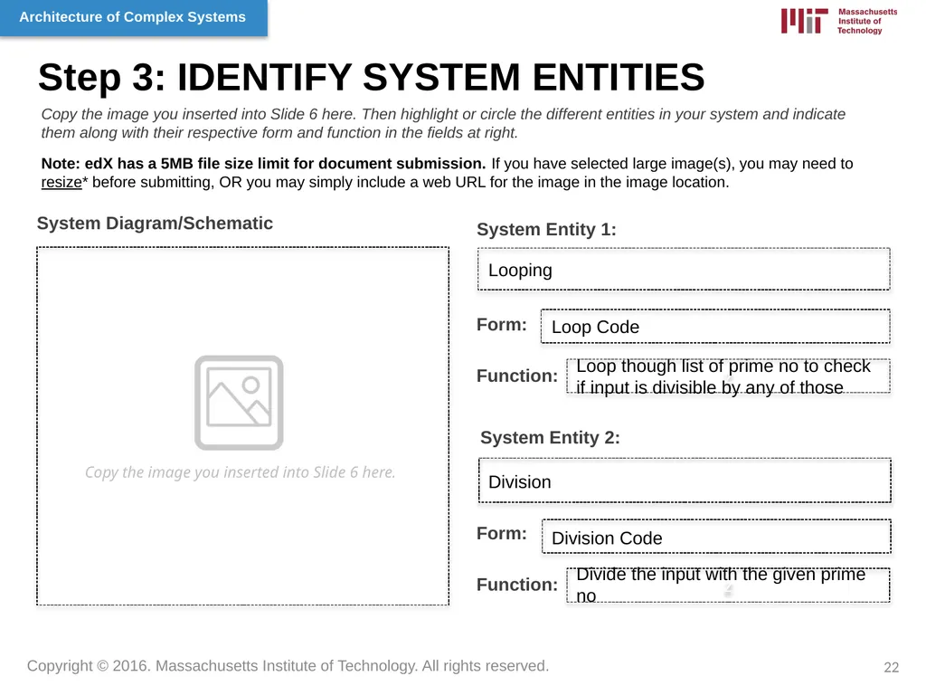
Step 3: IDENTIFY SYSTEM ENTITIES Copy the image you inserted into Slide 6 here. System Entity 1: System Diagram/Schematic z Copy the image you inserted into Slide 6 here. Then highlight or circle the different entities in your system and indicate them along with their respective form and function in the fields at right.
Note: edX has a 5MB file size limit for document submission. If you have selected large image(s), you may need to resize* before submitting, OR you may simply include a web URL for the image in the image location. Form: Function: System Entity 2: Form: Function: Looping Loop Code Loop though list of prime no to check if input is divisible by any of those Division Division Code Divide the input with the given prime no z 22<br>
Note: edX has a 5MB file size limit for document submission. If you have selected large image(s), you may need to resize* before submitting, OR you may simply include a web URL for the image in the image location. Form: Function: System Entity 2: Form: Function: Looping Loop Code Loop though list of prime no to check if input is divisible by any of those Division Division Code Divide the input with the given prime no z 22<br>
23
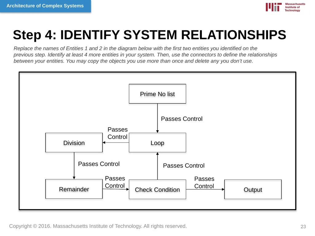
Step 4: IDENTIFY SYSTEM RELATIONSHIPS Loop Prime No list Division Remainder Check Condition Output Replace the names of Entities 1 and 2 in the diagram below with the first two entities you identified on the previous step. Identify at least 4 more entities in your system. Then, use the connectors to define the relationships between your entities. You may copy the objects you use more than once and delete any you don’t use. 23 Passes Control Passes
Control Passes Control Passes Control Passes
Control Passes
Control<br>
Control Passes Control Passes Control Passes
Control Passes
Control<br>
24
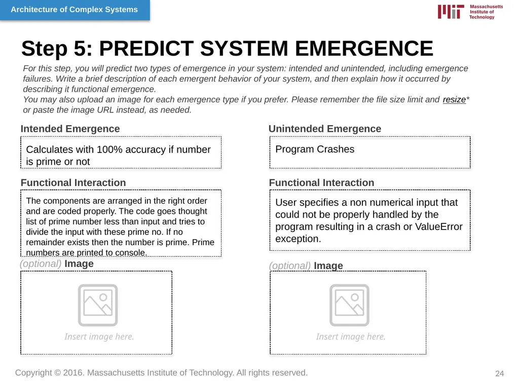
Step 5: PREDICT SYSTEM EMERGENCE Intended Emergence Unintended Emergence Functional Interaction (optional) Image Functional Interaction (optional) Image For this step, you will predict two types of emergence in your system: intended and unintended, including emergence failures. Write a brief description of each emergent behavior of your system, and then explain how it occurred by describing it functional emergence.
You may also upload an image for each emergence type if you prefer. Please remember the file size limit and resize* or paste the image URL instead, as needed. Insert image here. Insert image here. Calculates with 100% accuracy if number is prime or not Program Crashes The components are arranged in the right order and are coded properly. The code goes thought list of prime number less than input and tries to divide the input with these prime no. If no remainder exists then the number is prime. Prime numbers are printed to console. User specifies a non numerical input that could not be properly handled by the program resulting in a crash or ValueError exception. 24<br>
You may also upload an image for each emergence type if you prefer. Please remember the file size limit and resize* or paste the image URL instead, as needed. Insert image here. Insert image here. Calculates with 100% accuracy if number is prime or not Program Crashes The components are arranged in the right order and are coded properly. The code goes thought list of prime number less than input and tries to divide the input with these prime no. If no remainder exists then the number is prime. Prime numbers are printed to console. User specifies a non numerical input that could not be properly handled by the program resulting in a crash or ValueError exception. 24<br>
25
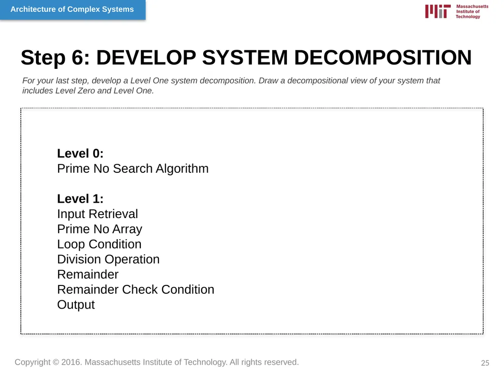
Step 6: DEVELOP SYSTEM DECOMPOSITION For your last step, develop a Level One system decomposition. Draw a decompositional view of your system that includes Level Zero and Level One. 25 Level 0:
Prime No Search Algorithm
Level 1:
Input Retrieval
Prime No Array
Loop Condition
Division Operation
Remainder
Remainder Check Condition
Output<br>
Prime No Search Algorithm
Level 1:
Input Retrieval
Prime No Array
Loop Condition
Division Operation
Remainder
Remainder Check Condition
Output<br>
26
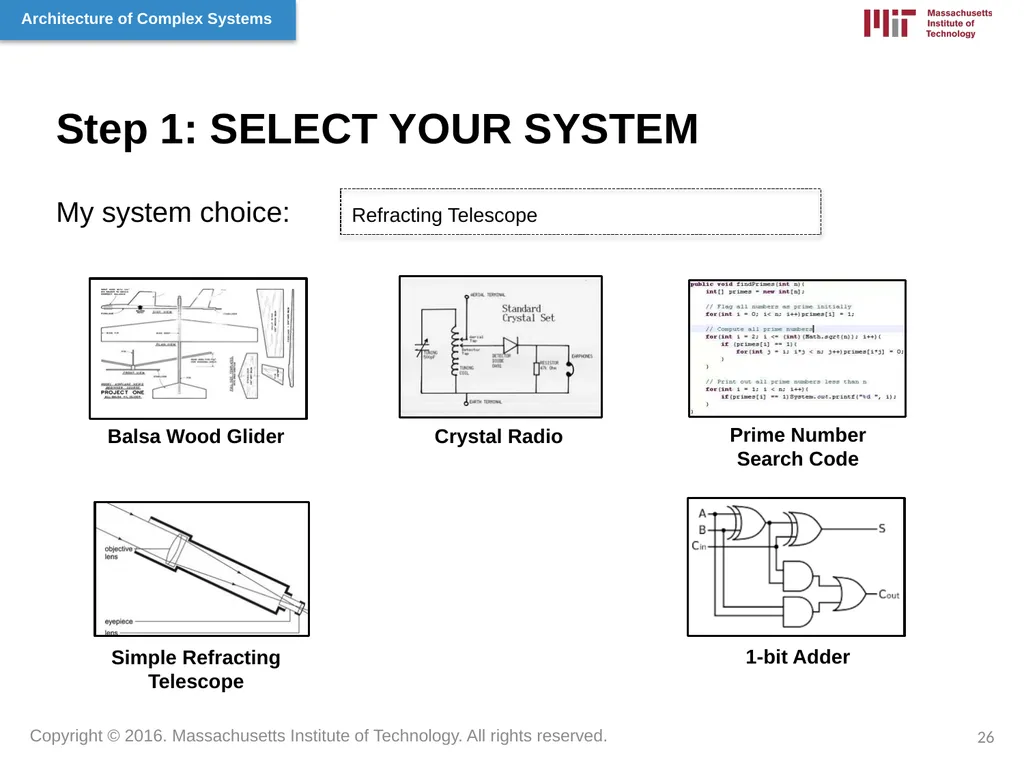
Step 1: SELECT YOUR SYSTEM My system choice: Refracting Telescope Balsa Wood Glider Crystal Radio Prime Number Search Code Simple Refracting Telescope 1-bit Adder 26<br>
27
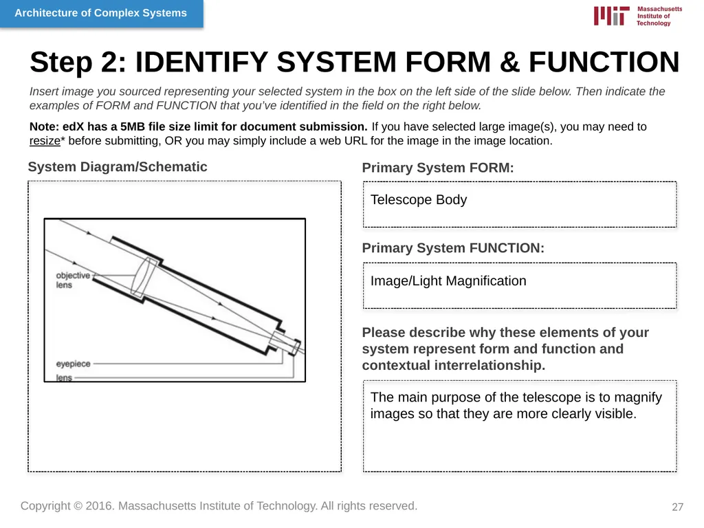
Step 2: IDENTIFY SYSTEM FORM & FUNCTION Primary System FORM: System Diagram/Schematic Insert image you sourced representing your selected system in the box on the left side of the slide below. Then indicate the examples of FORM and FUNCTION that you’ve identified in the field on the right below.
Note: edX has a 5MB file size limit for document submission. If you have selected large image(s), you may need to resize* before submitting, OR you may simply include a web URL for the image in the image location. Primary System FUNCTION: Please describe why these elements of your system represent form and function and contextual interrelationship. Telescope Body Image/Light Magnification The main purpose of the telescope is to magnify images so that they are more clearly visible. 27<br>
Note: edX has a 5MB file size limit for document submission. If you have selected large image(s), you may need to resize* before submitting, OR you may simply include a web URL for the image in the image location. Primary System FUNCTION: Please describe why these elements of your system represent form and function and contextual interrelationship. Telescope Body Image/Light Magnification The main purpose of the telescope is to magnify images so that they are more clearly visible. 27<br>
28
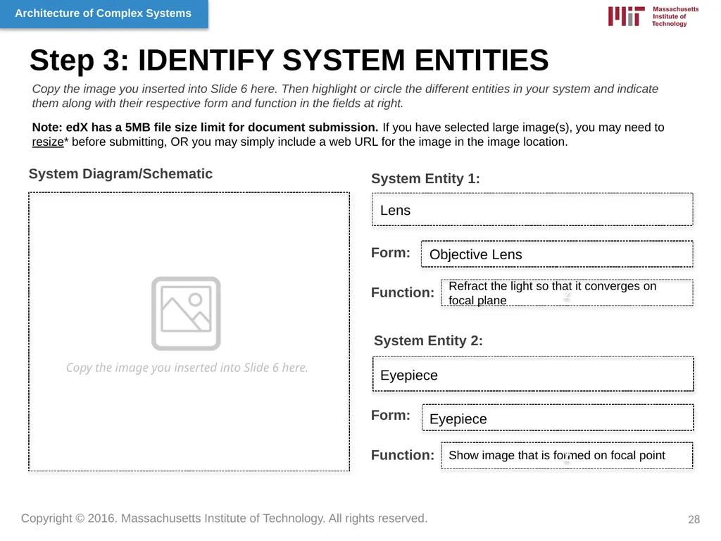
Step 3: IDENTIFY SYSTEM ENTITIES Copy the image you inserted into Slide 6 here. System Entity 1: System Diagram/Schematic z Copy the image you inserted into Slide 6 here. Then highlight or circle the different entities in your system and indicate them along with their respective form and function in the fields at right.
Note: edX has a 5MB file size limit for document submission. If you have selected large image(s), you may need to resize* before submitting, OR you may simply include a web URL for the image in the image location. Form: Function: System Entity 2: Form: Function: Lens Objective Lens Refract the light so that it converges on focal plane Eyepiece Eyepiece Show image that is formed on focal point z 28<br>
Note: edX has a 5MB file size limit for document submission. If you have selected large image(s), you may need to resize* before submitting, OR you may simply include a web URL for the image in the image location. Form: Function: System Entity 2: Form: Function: Lens Objective Lens Refract the light so that it converges on focal plane Eyepiece Eyepiece Show image that is formed on focal point z 28<br>
29
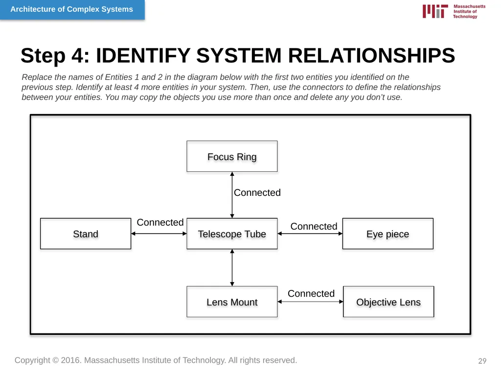
Step 4: IDENTIFY SYSTEM RELATIONSHIPS Objective Lens Eye piece Telescope Tube Focus Ring Stand Lens Mount Replace the names of Entities 1 and 2 in the diagram below with the first two entities you identified on the previous step. Identify at least 4 more entities in your system. Then, use the connectors to define the relationships between your entities. You may copy the objects you use more than once and delete any you don’t use. 29 Connected Connected Connected Connected<br>
30
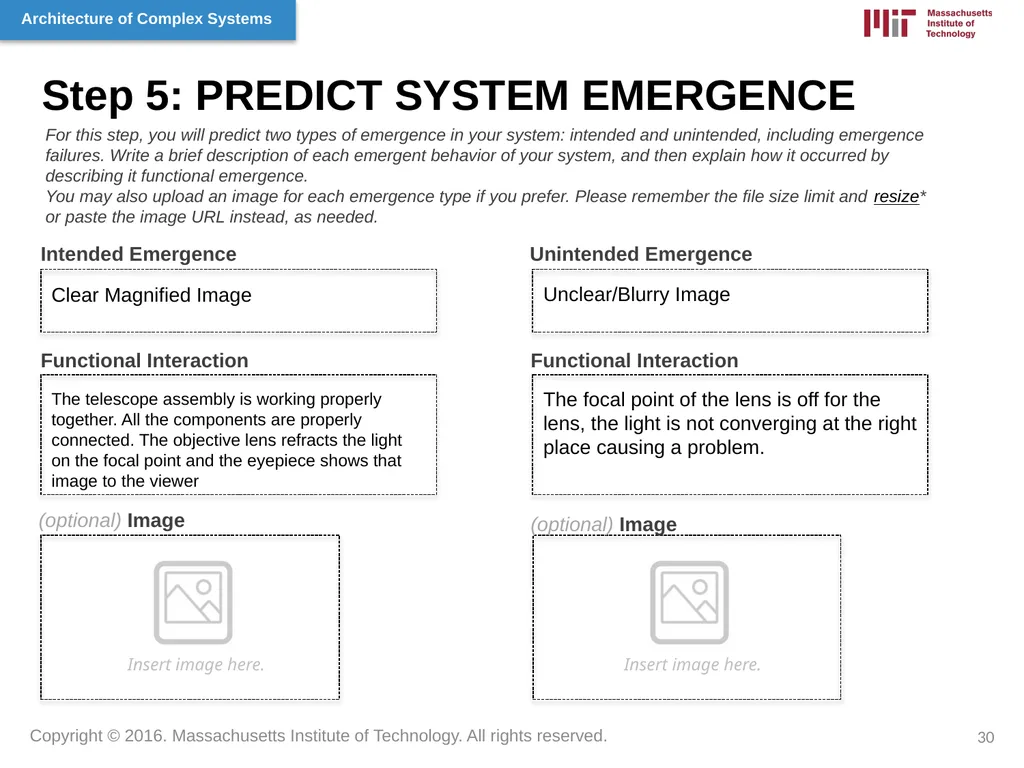
Step 5: PREDICT SYSTEM EMERGENCE Intended Emergence Unintended Emergence Functional Interaction (optional) Image Functional Interaction (optional) Image For this step, you will predict two types of emergence in your system: intended and unintended, including emergence failures. Write a brief description of each emergent behavior of your system, and then explain how it occurred by describing it functional emergence.
You may also upload an image for each emergence type if you prefer. Please remember the file size limit and resize* or paste the image URL instead, as needed. Insert image here. Insert image here. Clear Magnified Image Unclear/Blurry Image The telescope assembly is working properly together. All the components are properly connected. The objective lens refracts the light on the focal point and the eyepiece shows that image to the viewer The focal point of the lens is off for the lens, the light is not converging at the right place causing a problem. 30<br>
You may also upload an image for each emergence type if you prefer. Please remember the file size limit and resize* or paste the image URL instead, as needed. Insert image here. Insert image here. Clear Magnified Image Unclear/Blurry Image The telescope assembly is working properly together. All the components are properly connected. The objective lens refracts the light on the focal point and the eyepiece shows that image to the viewer The focal point of the lens is off for the lens, the light is not converging at the right place causing a problem. 30<br>
31
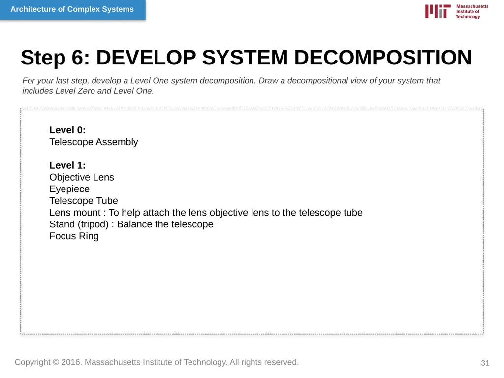
Step 6: DEVELOP SYSTEM DECOMPOSITION For your last step, develop a Level One system decomposition. Draw a decompositional view of your system that includes Level Zero and Level One. 31 Level 0:
Telescope Assembly
Level 1:
Objective Lens
Eyepiece
Telescope Tube
Lens mount : To help attach the lens objective lens to the telescope tube
Stand (tripod) : Balance the telescope
Focus Ring<br>
Telescope Assembly
Level 1:
Objective Lens
Eyepiece
Telescope Tube
Lens mount : To help attach the lens objective lens to the telescope tube
Stand (tripod) : Balance the telescope
Focus Ring<br>