AUSTRALIA-INDIA RESEARCH DEVELOPMENT IN RADIO ASTRONOMY MEETING (ARDRA) Challenges in the design of an antenna for the detection of Global 21cm EoR signal A. Raghunathan 15-11-2019 Collaborators: Somashekar.R, Girish B.S, Srivani K.S,
"AUSTRALIA-INDIA RESEARCH & DEVELOPMENT IN RADIO" is the property of its rightful owner. Permission is granted to
download and print the materials on this website for personal, non-commercial use only, and to display it
on your personal computer provided you do not modify the materials and that you retain all copyright
notices contained in the materials. By downloading content from our website, you accept the terms of this
agreement.
Presentation Transcript
01
AUSTRALIA-INDIA RESEARCH & DEVELOPMENT IN RADIO ASTRONOMY MEETING (ARDRA) Challenges in the design of an antenna for the detection of Global 21cm EoR signal A. Raghunathan 15-11-2019 Collaborators: Somashekar.R, Girish B.S, Srivani K.S, Saurabh Singh, Jishnu Nambissan T, Udaya Shankar, Ravi Subrahmanyan Raman Research Institute - Bangalore – 80<br>
02
Talk outline Global EoR signal and minimum system requirements for its detection
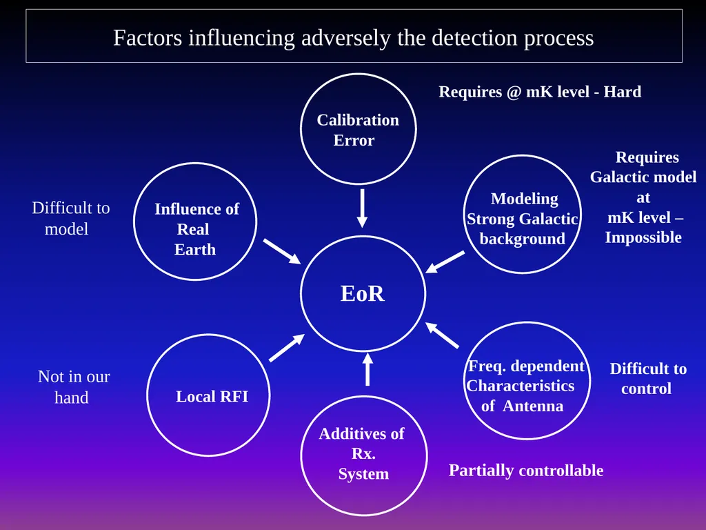
Factors influencing adversely the detection process
Methodology adopted to detect EoR signal
Primary requirements of the antenna used as a detector
Review of antennas built at the Raman Research Institute
Current status<br>
03
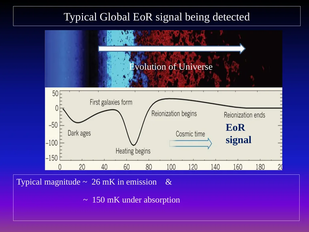
Typical Global EoR signal being detected Typical magnitude ~ 26 mK in emission &
~ 150 mK under absorption Evolution of Universe EoR signal<br>
04
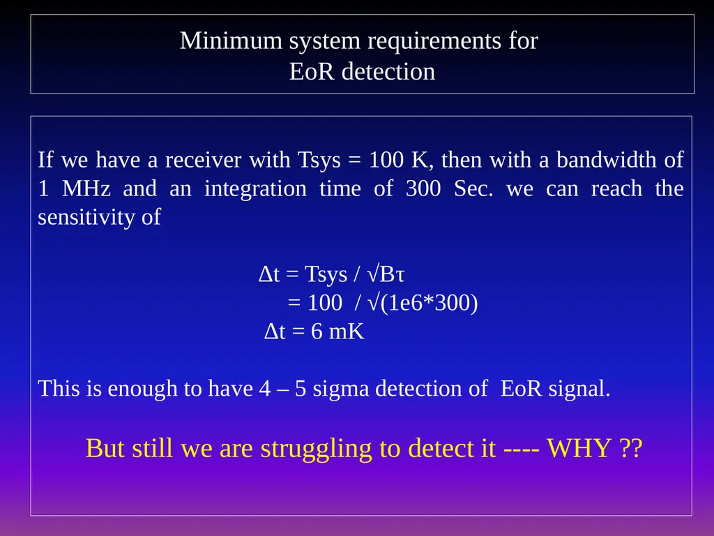
Minimum system requirements for EoR detection If we have a receiver with Tsys = 100 K, then with a bandwidth of 1 MHz and an integration time of 300 Sec. we can reach the sensitivity of
Δt = Tsys / √Bτ
= 100 / √(1e6*300)
Δt = 6 mK
This is enough to have 4 – 5 sigma detection of EoR signal.
But still we are struggling to detect it ---- WHY ??<br>
05
Factors influencing adversely the detection process Requires @ mK level - Hard Requires Galactic model at
mK level – Impossible Difficult to
control Partially controllable Not in our
hand Difficult to model<br>
06
We are optimistic about the detection because most of the contaminants are assumed to have smooth spectral response and not have frequency structures similar to EoR signal.
We are building the receiver system to have smooth spectral response so that EoR signal could be detected.<br>
07
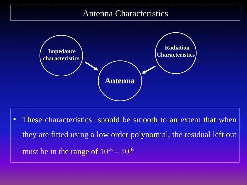
Antenna Characteristics These characteristics should be smooth to an extent that when they are fitted using a low order polynomial, the residual left out must be in the range of 10-5 – 10-6<br>
08
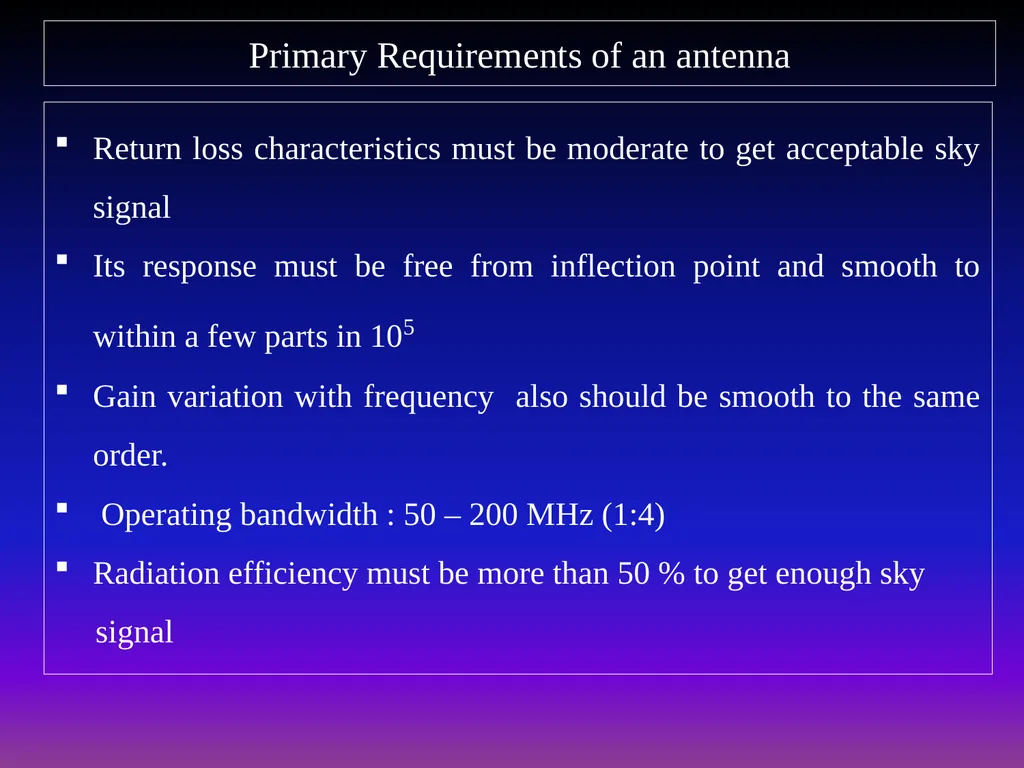
Primary Requirements of an antenna Return loss characteristics must be moderate to get acceptable sky signal
Its response must be free from inflection point and smooth to within a few parts in 105
Gain variation with frequency also should be smooth to the same order.
Operating bandwidth : 50 – 200 MHz (1:4)
Radiation efficiency must be more than 50 % to get enough sky
signal<br>
09
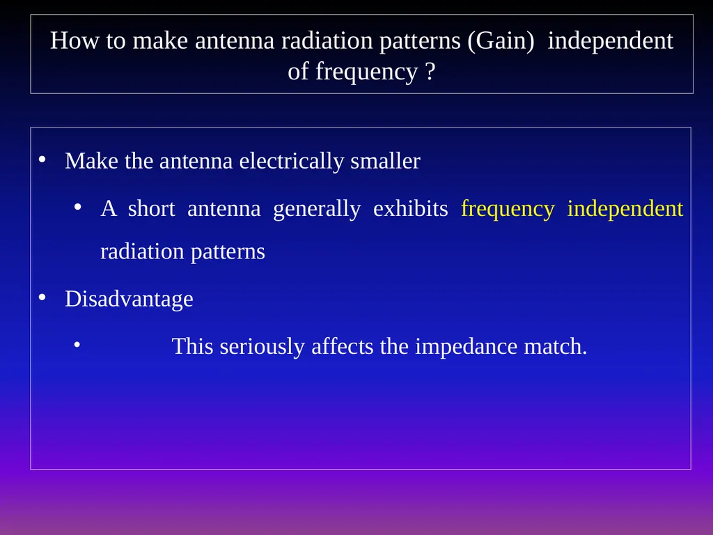
How to make antenna radiation patterns (Gain) independent of frequency ? Make the antenna electrically smaller
A short antenna generally exhibits frequency independent radiation patterns
Disadvantage
This seriously affects the impedance match.<br>
10
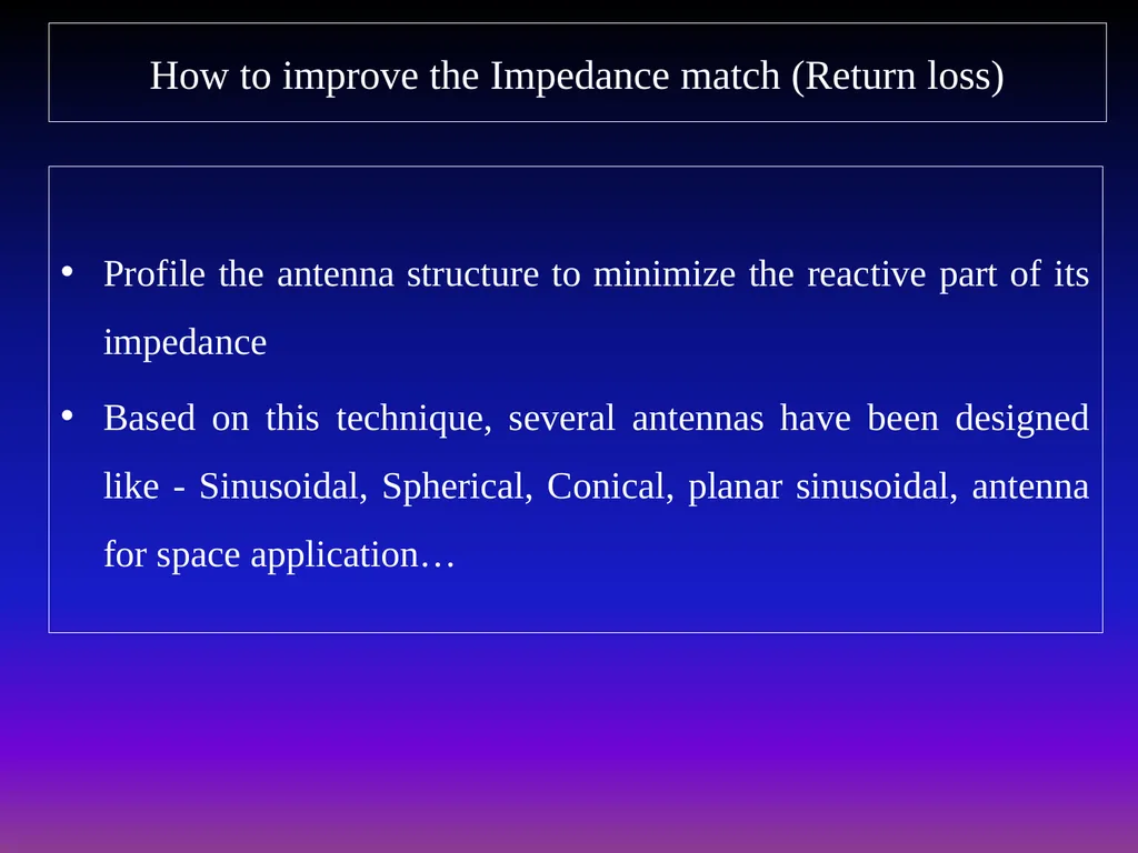
How to improve the Impedance match (Return loss) Profile the antenna structure to minimize the reactive part of its impedance
Based on this technique, several antennas have been designed like - Sinusoidal, Spherical, Conical, planar sinusoidal, antenna for space application…<br>
11
Antennas built at RRI for EoR expt. 87.5-175MHz 40-200MHz 50-100 MHz Return loss Radiation pattern<br>
12
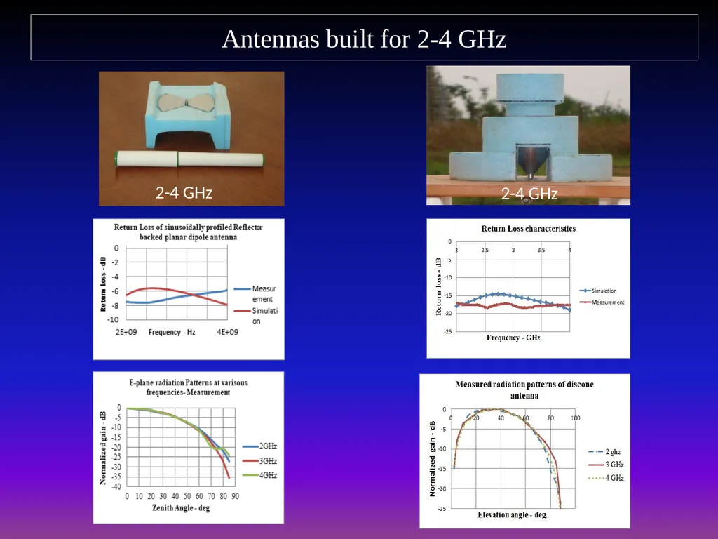
Antennas built for 2-4 GHz 2-4 GHz 2-4 GHz<br>
13
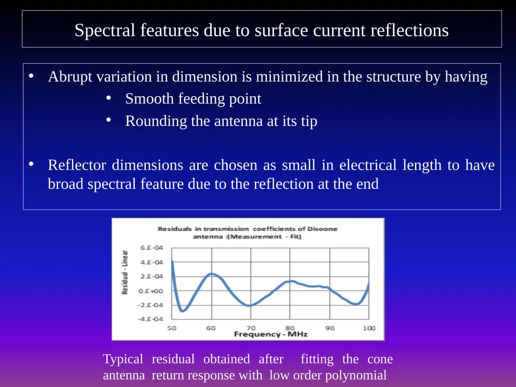
Spectral features due to surface current reflections Abrupt variation in dimension is minimized in the structure by having
Smooth feeding point
Rounding the antenna at its tip
Reflector dimensions are chosen as small in electrical length to have broad spectral feature due to the reflection at the end Typical residual obtained after fitting the cone antenna return response with low order polynomial<br>
14
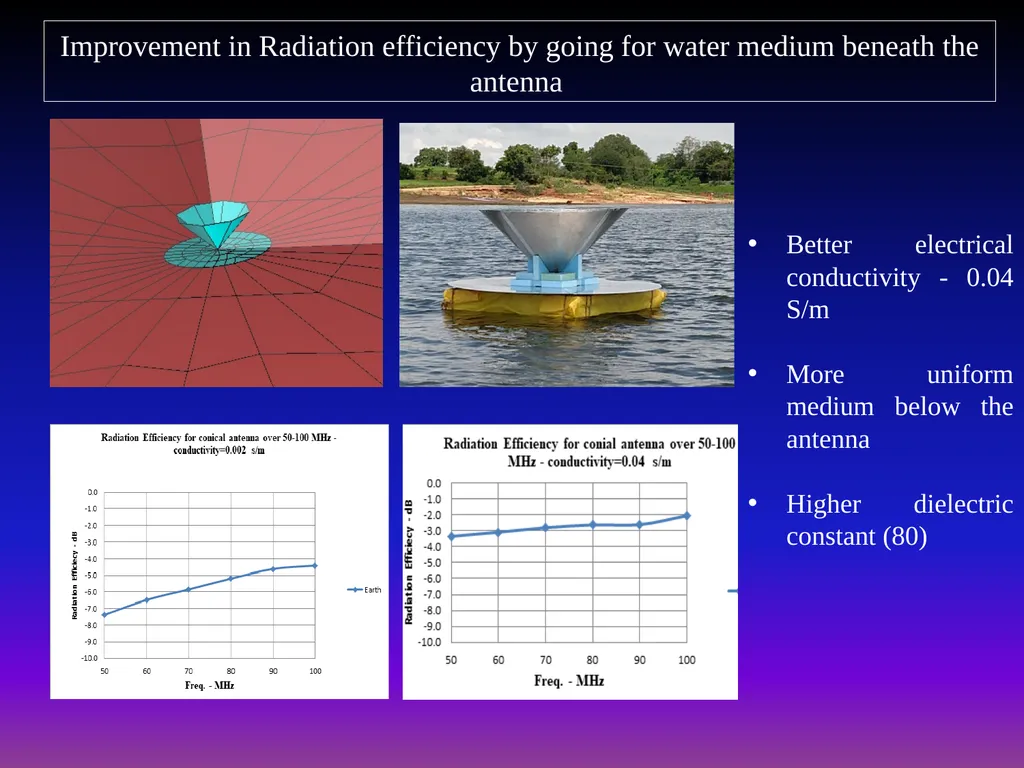
Improvement in Radiation efficiency by going for water medium beneath the antenna Better electrical conductivity - 0.04 S/m
More uniform medium below the antenna
Higher dielectric constant (80)<br>
15
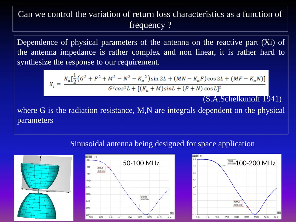
Can we control the variation of return loss characteristics as a function of frequency ? Dependence of physical parameters of the antenna on the reactive part (Xi) of the antenna impedance is rather complex and non linear, it is rather hard to synthesize the response to our requirement.
(S.A.Schelkunoff 1941)
where G is the radiation resistance, M,N are integrals dependent on the physical parameters Sinusoidal antenna being designed for space application 50-100 MHz 100-200 MHz<br>
16
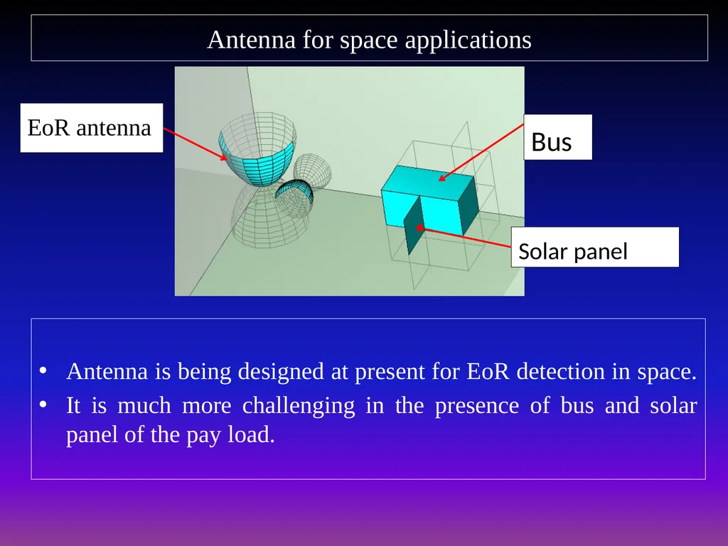
Antenna for space applications Antenna is being designed at present for EoR detection in space.
It is much more challenging in the presence of bus and solar panel of the pay load. Bus Solar panel EoR antenna<br>
17
Conclusion Antenna design for Global EoR detection experiment is challenging
It is required that the antenna’s spectral response be smooth to few parts in 105 so that its features do not confuse the detection process over more than an octave bandwidth
Its radiation efficiency also must be acceptable to get more sky signal.
Antenna design for space application is much more harder than on the ground due to the influence of bus and solar panel.<br>