
Automotive Technology Principles, Diagnosis, and
JO
Published · 59 slides · 0 views

1 / 1


















Description
Automotive Technology Principles, Diagnosis, and Service Sixth Edition Chapter 53 Cranking System Diagnosis and Service Copyright 2018, 2015, 2011 Pearson Education, Inc. All Rights Reserved LEARNING OBJECTIVES (1 of 2) 53.1 Explain the
Related Topics
Share
Embed code
Download this presentation From Below
"Automotive Technology Principles, Diagnosis, and" is the property of its rightful owner. Permission is granted to download and print the materials on this website for personal, non-commercial use only, and to display it on your personal computer provided you do not modify the materials and that you retain all copyright notices contained in the materials. By downloading content from our website, you accept the terms of this agreement.
Presentation Transcript
01
Automotive Technology Principles, Diagnosis, and Service Sixth Edition Chapter 53 Cranking System Diagnosis and Service Copyright © 2018, 2015, 2011 Pearson Education, Inc. All Rights Reserved<br>
02
LEARNING OBJECTIVES (1 of 2) 53.1 Explain the procedure to troubleshoot a starting system problem.
53.2 Discuss how to perform a voltage drop test on the cranking circuit.
53.3 Perform control circuit testing and starter amperage test, and determine necessary action.
53.4 Describe the procedure to remove a starter motor.<br>
53.2 Discuss how to perform a voltage drop test on the cranking circuit.
53.3 Perform control circuit testing and starter amperage test, and determine necessary action.
53.4 Describe the procedure to remove a starter motor.<br>
03
LEARNING OBJECTIVES (2 of 2) 53.5 Explain starter motor service and bench testing.
53.6 Describe the procedure to install a starter motor.
53.7 Describe how to ensure proper clearance between the starter pinion and the engine flywheel.
53.8 This chapter will help prepare for the ASE Electrical/Electronic Systems (A6) certification test content area “C” (Battery and Starting Systems Diagnosis and Repair).<br>
53.6 Describe the procedure to install a starter motor.
53.7 Describe how to ensure proper clearance between the starter pinion and the engine flywheel.
53.8 This chapter will help prepare for the ASE Electrical/Electronic Systems (A6) certification test content area “C” (Battery and Starting Systems Diagnosis and Repair).<br>
04
STARTING SYSTEM TROUBLESHOOTING PROCEDURE Overview
Check all system components for proper operation
Steps Involved
Step 1: Verify the customer concern.
Step 2: Visually inspect the battery and battery connections.
Step 3:Test battery condition.
Step 4: Check the control circuit.
Step 5: Check voltage drop of the starter circuit.<br>
Check all system components for proper operation
Steps Involved
Step 1: Verify the customer concern.
Step 2: Visually inspect the battery and battery connections.
Step 3:Test battery condition.
Step 4: Check the control circuit.
Step 5: Check voltage drop of the starter circuit.<br>
05
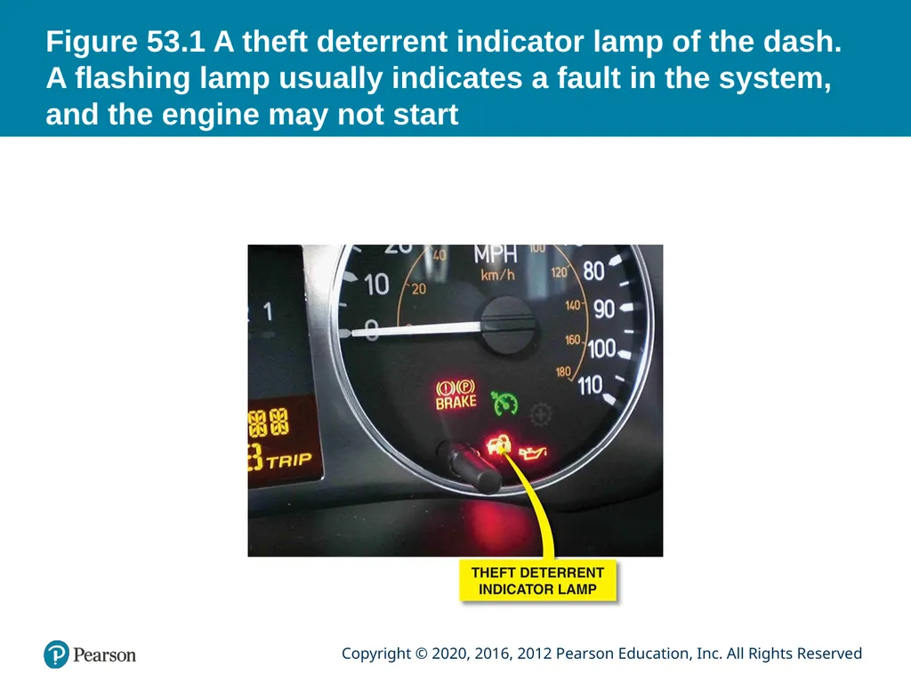
Figure 53.1 A theft deterrent indicator lamp of the dash. A flashing lamp usually indicates a fault in the system, and the engine may not start<br>
06
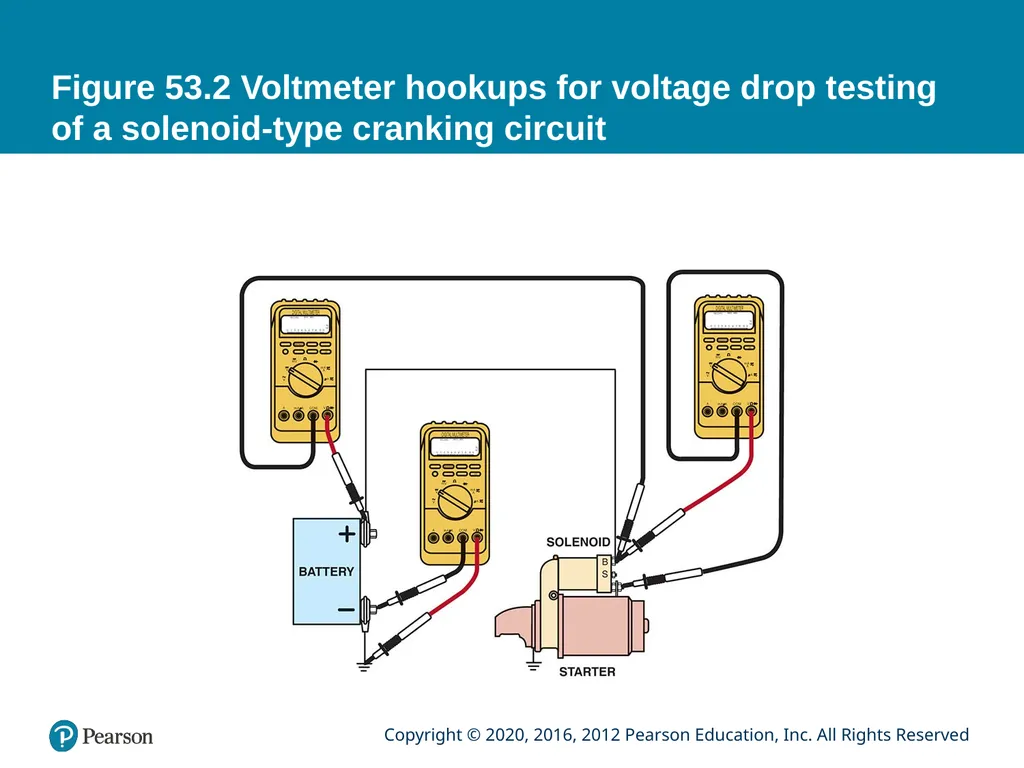
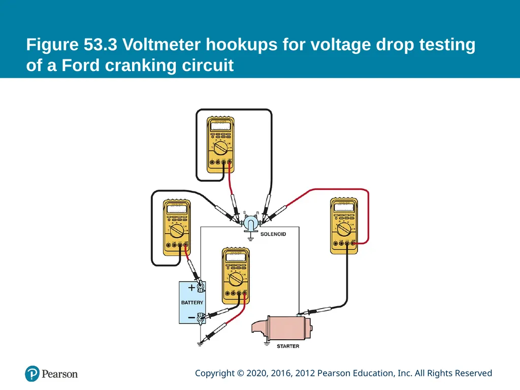
VOLTAGE DROP TESTING Voltage drop is the drop in voltage that occurs when current is flowing through a resistance.
Test Procedure
Disable the ignition or fuel injection
Connect voltmeter between battery and starter motor
Crank the engine and observe the reading while cranking
Test voltage drop across solenoid
Check voltage drop on ground side of circuit<br>
Test Procedure
Disable the ignition or fuel injection
Connect voltmeter between battery and starter motor
Crank the engine and observe the reading while cranking
Test voltage drop across solenoid
Check voltage drop on ground side of circuit<br>
07
Figure 53.2 Voltmeter hookups for voltage drop testing of a solenoid-type cranking circuit<br>
08
Figure 53.3 Voltmeter hookups for voltage drop testing of a Ford cranking circuit<br>
09
Animation:
Starter Circuit, Voltage Drop Tests
(The animation will automatically start in a few seconds)<br>
10
Figure 53.4 Place one voltmeter lead on the battery terminal and the other voltmeter lead on the cable end and crank the engine. The voltmeter reads the difference in voltage between the two leads, which should not exceed 0.20 volt (200 millivolts)<br>
11
QUESTION 1: ? What is the purpose of the voltage drop testing?<br>
12
ANSWER 1: To ensure no unwanted resistance exists in the circuit.<br>
13
CONTROL CIRCUIT TESTING An open or break anywhere in the control circuit prevents the operation of the starter motor.
Components to checked:
Neutral safety or clutch switch
Blown crank fuse
Open at the ignition switch in the crank position
Starter relay or module, if equipped
Antitheft controls<br>
Components to checked:
Neutral safety or clutch switch
Blown crank fuse
Open at the ignition switch in the crank position
Starter relay or module, if equipped
Antitheft controls<br>
14
STARTER AMPERAGE TEST Reason for Starter Amperage Test
Slow or no cranking of the engine
Test Preparation
Battery is sufficiently charged (75% or more)
Specifications:
4-cylinder engines = 150 to 185 amperes
6-cylinder engines = 160 to 200 amperes
8-cylinder engines = 185 to 250 amperes<br>
Slow or no cranking of the engine
Test Preparation
Battery is sufficiently charged (75% or more)
Specifications:
4-cylinder engines = 150 to 185 amperes
6-cylinder engines = 160 to 200 amperes
8-cylinder engines = 185 to 250 amperes<br>
15
Figure 53.5 A starter amperage tester uses an amp probe around the positive or negative battery cables<br>
16
STARTER REMOVAL Procedure:
Disconnect the negative battery cable.
Hoist the vehicle safely (as needed).
Remove the starter retaining bolts
Gain access to the wiring
Disconnect and label the wire(s)
Inspect the flywheel (flexplate) for ring gear damage.<br>
Disconnect the negative battery cable.
Hoist the vehicle safely (as needed).
Remove the starter retaining bolts
Gain access to the wiring
Disconnect and label the wire(s)
Inspect the flywheel (flexplate) for ring gear damage.<br>
17
Figure 53.6 The starter is located under the intake manifold on this Cadillac Northstar engine<br>
18
QUESTION 2: ? What are the steps in removing a typical starter motor?<br>
19
ANSWER 2: Disconnect the negative battery cable.
Hoist the vehicle safely (as needed).
Remove the starter retaining bolts
Gain access to the wiring
Disconnect and label the wire(s)
Inspect the flywheel (flexplate) for ring gear damage.<br>
Hoist the vehicle safely (as needed).
Remove the starter retaining bolts
Gain access to the wiring
Disconnect and label the wire(s)
Inspect the flywheel (flexplate) for ring gear damage.<br>
20
STARTER MOTOR SERVICE Purpose
Most starter motors are replaced as an assembly
Some older starters can be serviced
Inspection and Testing
Solenoid
Starter armature
Starter motor field coils
Starter brush inspection<br>
Most starter motors are replaced as an assembly
Some older starters can be serviced
Inspection and Testing
Solenoid
Starter armature
Starter motor field coils
Starter brush inspection<br>
21
Figure 53.7 An exploded view of a typical solenoid-operated starter<br>
22
Figure 53.8 GM solenoid ohmmeter check. The reading between 1 and 3 (S terminal and ground) should be 0.4 to 0.6 ohm (hold-in winding). The reading between 1 and 2 (S terminal and M terminal) should be 0.2 to 0.4 ohm (pull-in winding)<br>
23
Figure 53.9 Measuring an armature shaft for runout using a dial indicator and V-blocks<br>
24
Figure 53.10 Replacement starter brushes should be installed so the beveled edge matches the rotation of the commutator<br>
25
BENCH TESTING Every starter should be tested before installation in a vehicle.
Bench testing is the usual method of ensuring starter has been properly repaired.
Clamping the starter in a vise
Connect heavy-gauge jumper wires (minimum 4 gauge) to both a good battery and the starter.
The starter motor operates within specifications.<br>
Bench testing is the usual method of ensuring starter has been properly repaired.
Clamping the starter in a vise
Connect heavy-gauge jumper wires (minimum 4 gauge) to both a good battery and the starter.
The starter motor operates within specifications.<br>
26
QUESTION 3: ? What is the purpose of bench testing the starter motor?<br>
27
ANSWER 3: To ensure it operates properly before it is reinstalled on the vehicle.<br>
28
STARTER INSTALLATION Check service information for the exact wiring connections
Verify that all electrical connections on the starter-motor are in good condition
Attach the power and control wires
Install the starter, and torque all the fasteners to factory specifications
Perform a starter amperage draw test and check for proper engine cranking.<br>
Verify that all electrical connections on the starter-motor are in good condition
Attach the power and control wires
Install the starter, and torque all the fasteners to factory specifications
Perform a starter amperage draw test and check for proper engine cranking.<br>
29
STARTER DRIVE TO FLYWHEEL CLEARANCE Need for Shims
Many starters use shims, which are thin metal strips, between the flywheel and the engine block mounting pad to provide the proper clearance.
Symptoms of Clearance Problems
Clearance too Great: A high pitched whine during cranking.
Clearance to Small: The starter may bind, crank slowly.<br>
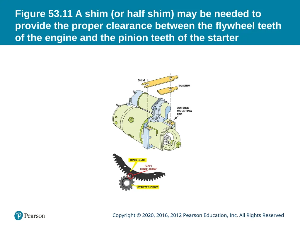
Many starters use shims, which are thin metal strips, between the flywheel and the engine block mounting pad to provide the proper clearance.
Symptoms of Clearance Problems
Clearance too Great: A high pitched whine during cranking.
Clearance to Small: The starter may bind, crank slowly.<br>
30
Figure 53.11 A shim (or half shim) may be needed to provide the proper clearance between the flywheel teeth of the engine and the pinion teeth of the starter<br>
31
STARTING SYSTEM SYMPTOM GUIDE The following list may help to identify possible starting system concerns.
Starter motor whines
Starter rotates slowly
Starter fails to rotate
Starter produces grinding noise
Starter clicks when engaged<br>
Starter motor whines
Starter rotates slowly
Starter fails to rotate
Starter produces grinding noise
Starter clicks when engaged<br>
32
STARTER OVERHAUL<br>
33
1. This dirty and greasy starter can be restored to useful
service.<br>
34
2. The connecting wire between the solenoid and the
starter is removed.<br>
35
3. An old starter field housing is being used to support the drive-end housing of the starter as it is being disassembled. This rebuilder is using an electric impact wrench to remove the solenoid fasteners.<br>
36
4. A Torx driver is used to remove the solenoid attaching screws.<br>
37
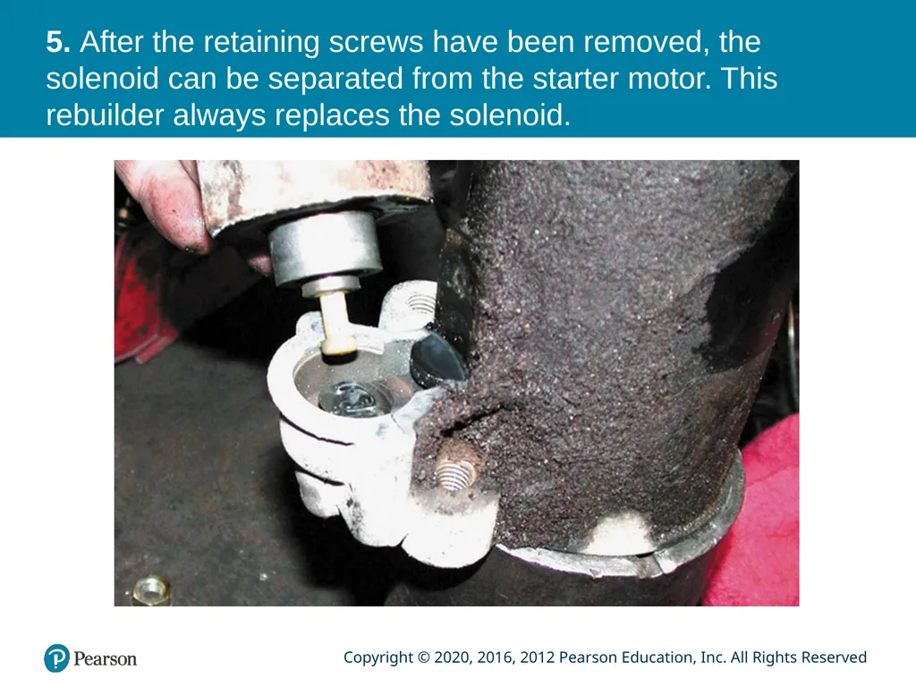
5. After the retaining screws have been removed, the solenoid can be separated from the starter motor. This rebuilder always replaces the solenoid.<br>
38
6. The through bolts are being removed.<br>
39
7. The brush end plate is removed.<br>
40
8. The armature assembly is removed from the field frame.<br>
41
9. Notice that the length of a direct-drive starter armature (top) is the same length as the overall length of a gear-reduction armature, except smaller in diameter.<br>
42
10. A light tap with a hammer dislodges the armature thrust ball (in the palm of the hand) from the center of the gear-reduction assembly.<br>
43
11. This figure shows the planetary ring gear and pinion gears.<br>
44
12. A close-up of one of the planetary gears, which shows the small needle bearings on the inside.<br>
45
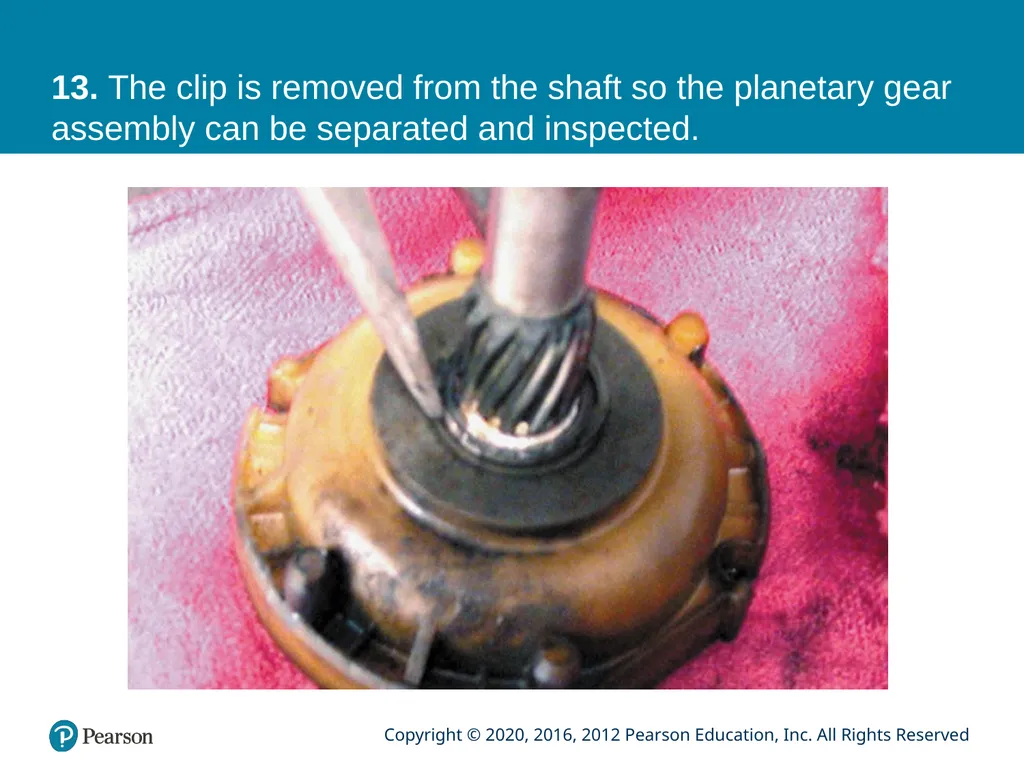
13. The clip is removed from the shaft so the planetary gear assembly can be separated and inspected.<br>
46
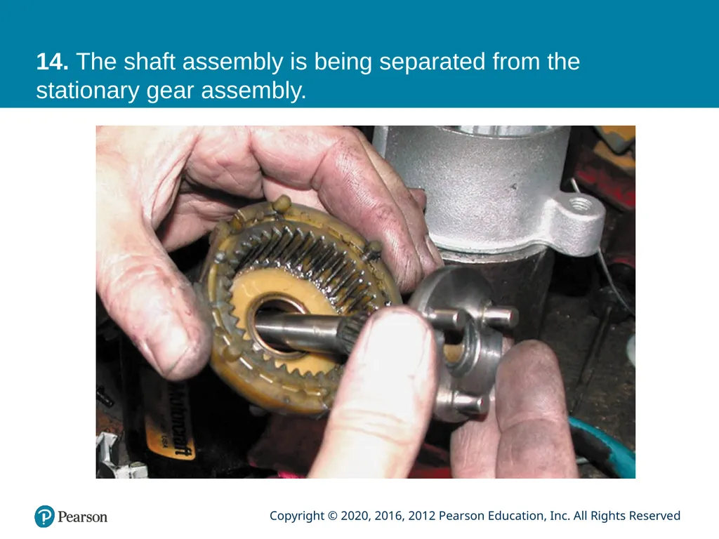
14. The shaft assembly is being separated from the stationary gear assembly.<br>
47
15. The commutator on the armature is discolored and the brushes may not have been making good contact with the segments.<br>
48
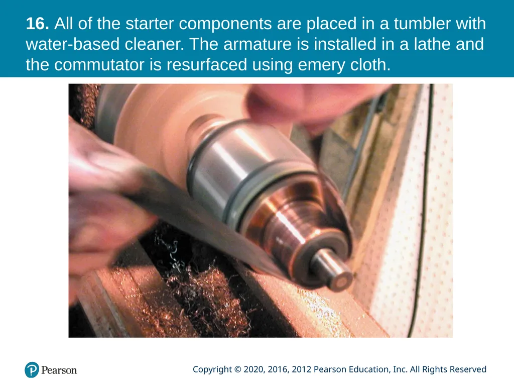
16. All of the starter components are placed in a tumbler with water-based cleaner. The armature is installed in a lathe and the commutator is resurfaced using emery cloth.<br>
49
17. The finished commutator looks like new.<br>
50
18. Starter reassembly begins by installing a new starter drive on the shaft assembly. The stop ring and stop ring retainer are then installed.<br>
51
19. The gear-reduction assembly is positioned along with the shift fork (drive lever) into the cleaned drive-end housing.<br>
52
20. After gear retainer has been installed over the gear reduction assembly, the armature is installed.<br>
53
21. New brushes are being installed into the brush holder assembly.<br>
54
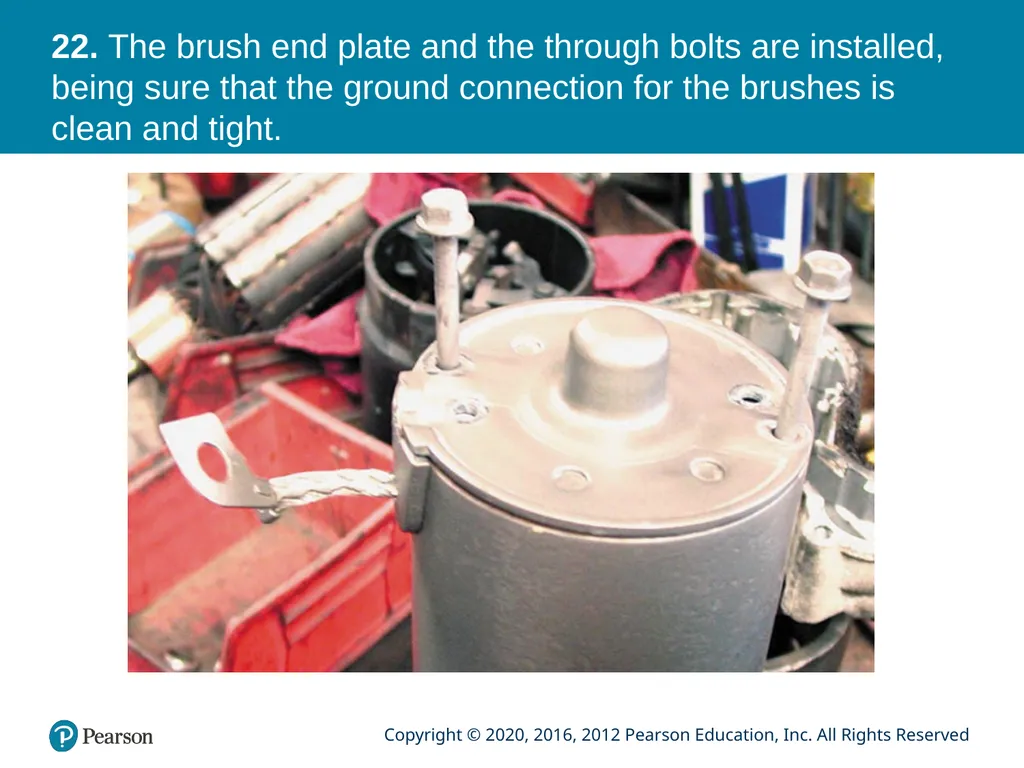
22. The brush end plate and the through bolts are installed, being sure that the ground connection for the brushes is clean and tight.<br>
55
23. This starter was restored to useful service by replacing the solenoid, the brushes, and the starter drive assembly, plus a thorough cleaning and attention to detail in the reassembly.<br>
56
Video Links (Internet Access Required) Charging system test (time 4:49)
Starter diagnosis (time 15:58)
Starter replacement (time 3:09)
Clutch switch (time 2:40)
Car no start (time 4:20)
Starter test (time 8:59)
No crank/no start diagnostics (time 6:20)
Remote starter switch (time 3:58)
Starter (time 5:32)
Solenoid testing (time 2:59)<br>
Starter diagnosis (time 15:58)
Starter replacement (time 3:09)
Clutch switch (time 2:40)
Car no start (time 4:20)
Starter test (time 8:59)
No crank/no start diagnostics (time 6:20)
Remote starter switch (time 3:58)
Starter (time 5:32)
Solenoid testing (time 2:59)<br>
57
Video Links (Internet Access Required) Starter diagnosis (time 14:59)
Starter system voltage drop (time 1:55)
No start no crank testing (time 4:28)
Voltage drop part 1 (time 3:41)
Voltage drop part 2 (time 9:29)
Voltage drop part 3 (time 9:42)
Voltage drop part 4 (time 9:39)
Ignition lock cylinder (time 2:29)
Starter (time 9:47)
Clutch switch (time 5:10)<br>
Starter system voltage drop (time 1:55)
No start no crank testing (time 4:28)
Voltage drop part 1 (time 3:41)
Voltage drop part 2 (time 9:29)
Voltage drop part 3 (time 9:42)
Voltage drop part 4 (time 9:39)
Ignition lock cylinder (time 2:29)
Starter (time 9:47)
Clutch switch (time 5:10)<br>
58
Video Links (Internet Access Required) Ignition switch replacement (time 4:26)
How to Change (remove & replace) a Starter (time 11:41)<br>
How to Change (remove & replace) a Starter (time 11:41)<br>
59
Copyright<br>