04
BATTERY SERVICE SAFETY CONSIDERATIONS Hazards
Batteries contain acid and release explosive gases (hydrogen and oxygen) during normal charging and discharging cycles.
Safety Procedures
Disconnect the negative battery cable from the battery.
Wear eye protection and protective clothing
Follow all safety precautions
Never jump-start a frozen battery<br>
05
SYMPTOMS OF A WEAK OR DEFECTIVE BATTERY The following warning signs indicate that a battery is near the end of its useful life.
Uses water in one or more cells.
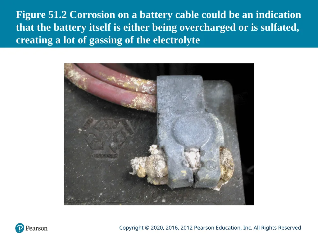
Excessive corrosion on battery cables or connections.
Slower than normal engine cranking.<br>
06
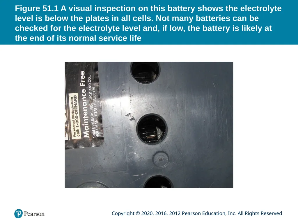
Figure 51.1 A visual inspection on this battery shows the electrolyte level is below the plates in all cells. Not many batteries can be checked for the electrolyte level and, if low, the battery is likely at the end of its normal service life<br>
07
Figure 51.2 Corrosion on a battery cable could be an indication that the battery itself is either being overcharged or is sulfated, creating a lot of gassing of the electrolyte<br>
08
BATTERY MAINTENANCE Need for Maintenance
Most new-style batteries are of a maintenance-free design
Battery Terminal Cleaning
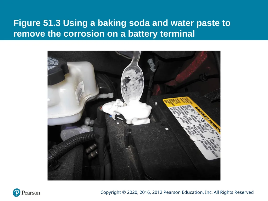
Use 1 tablespoon of baking soda in 1 quart (liter) of water to neutralize the acid.
Battery Hold-Down
The hold-down bracket should be snug enough to prevent battery movement.<br>
09
Figure 51.3 Using a baking soda and water paste to remove the corrosion on a battery terminal<br>
10
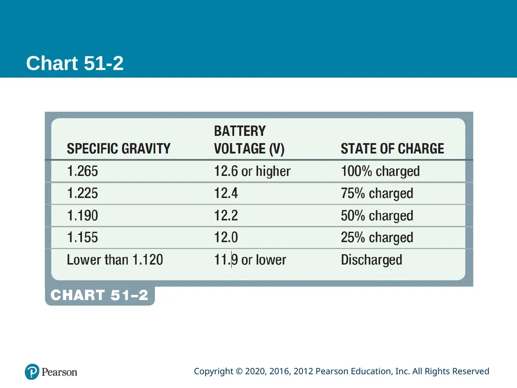
BATTERY VOLTAGE TEST State of Charge
Testing the battery voltage with a voltmeter.
Sometimes referred to as an open circuit battery voltage test.
Surface charge may need to be removed before testing.<br>
11
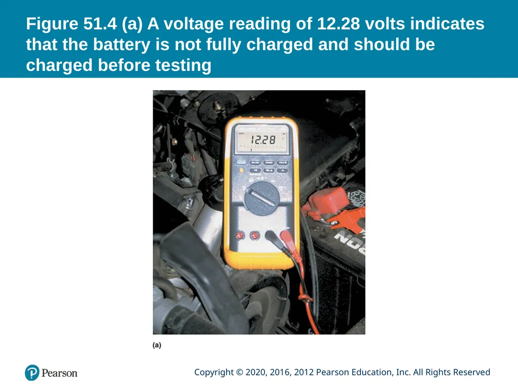
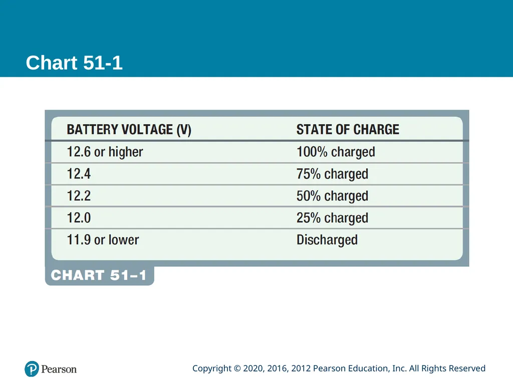
Figure 51.4 (a) A voltage reading of 12.28 volts indicates that the battery is not fully charged and should be charged before testing<br>
12
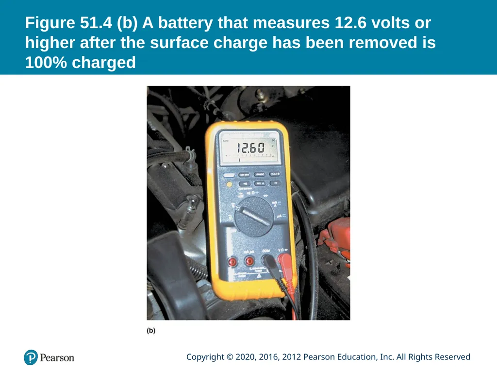
Figure 51.4 (b) A battery that measures 12.6 volts or higher after the surface charge has been removed is 100% charged<br>
14
QUESTION 1: ? What is the battery state of charge test?<br>
15
ANSWER 1: An open circuit test of the battery with a voltmeter after the surface charge has been removed.<br>
16
HYDROMETER TESTING If the battery has removable filler caps, the specific gravity of the electrolyte can also be checked.
A hydrometer is a tester that measures the specific gravity.<br>
17
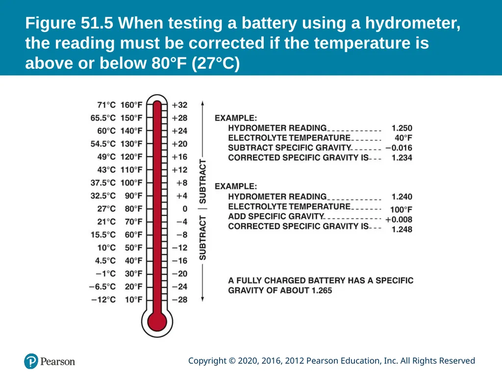
Figure 51.5 When testing a battery using a hydrometer, the reading must be corrected if the temperature is above or below 80°F (27°C)<br>
19
BATTERY LOAD TESTING Terminology
A load test measures the number of amperes the battery can supply for 30 seconds at 0°F (-18°C).
Test Procedure
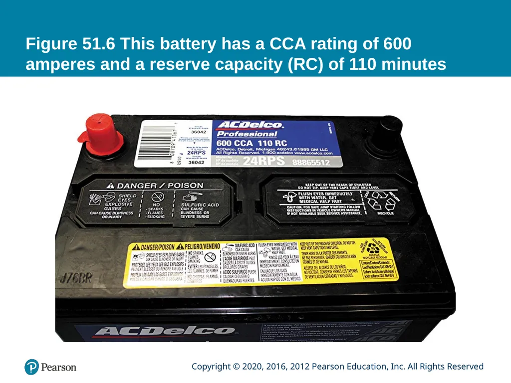
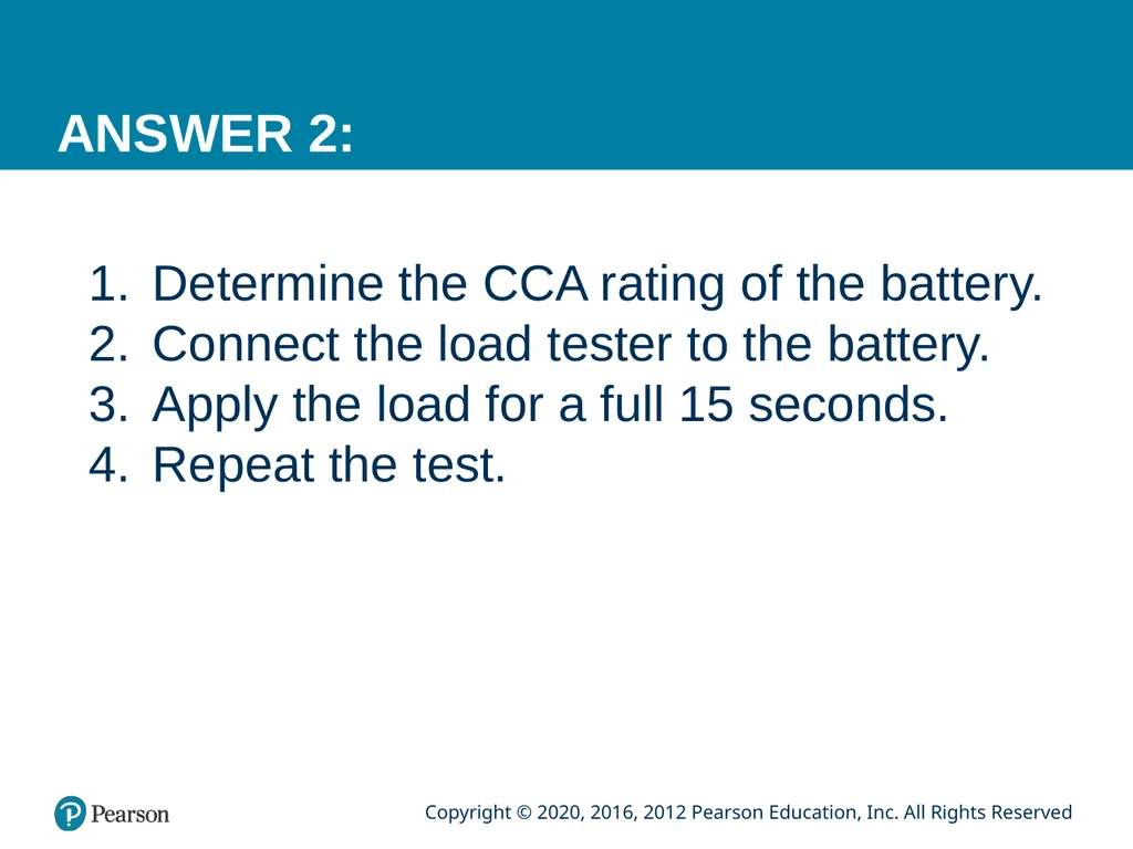
Determine the CCA rating of the battery.
Connect the load tester to the battery.
Apply the load for a full 15 seconds.
Repeat the test.<br>
20
Figure 51.6 This battery has a CCA rating of 600 amperes and a reserve capacity (RC) of 110 minutes<br>
21
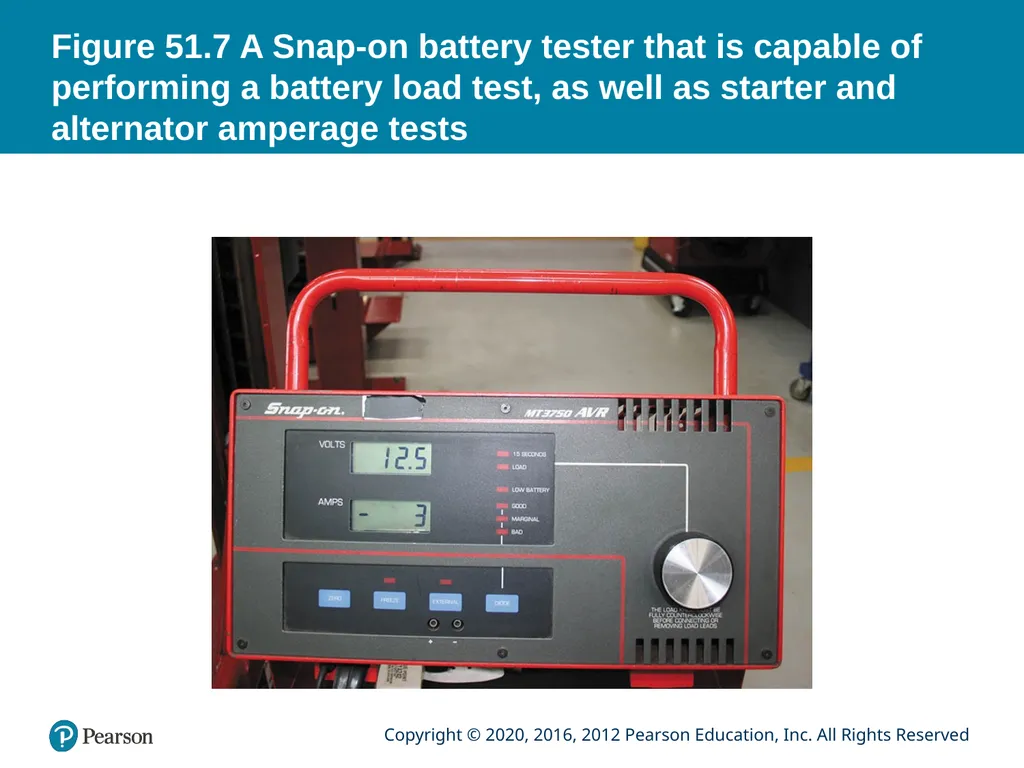
Figure 51.7 A Snap-on battery tester that is capable of performing a battery load test, as well as starter and alternator amperage tests<br>
22
QUESTION 2: ? What are the steps for performing a battery load test?<br>
23
ANSWER 2: Determine the CCA rating of the battery.
Connect the load tester to the battery.
Apply the load for a full 15 seconds.
Repeat the test.<br>
24
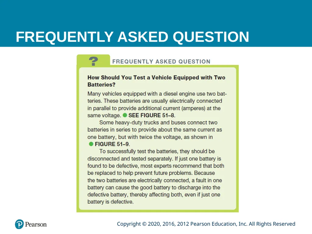
FREQUENTLY ASKED QUESTION<br>
25
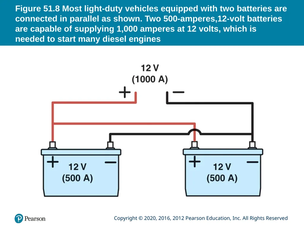
Figure 51.8 Most light-duty vehicles equipped with two batteries are connected in parallel as shown. Two 500-amperes,12-volt batteries are capable of supplying 1,000 amperes at 12 volts, which is needed to start many diesel engines<br>
26
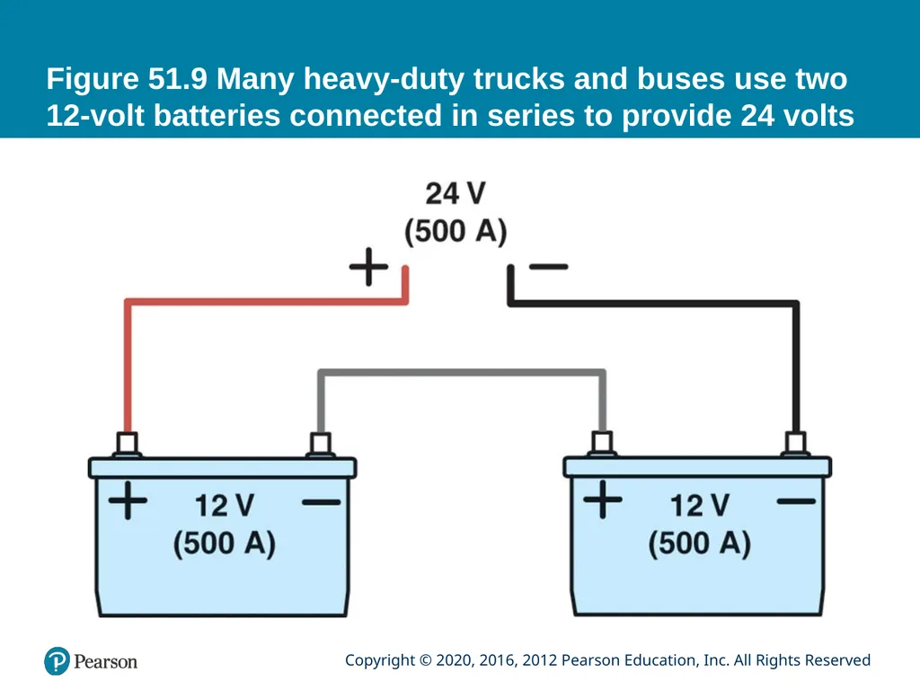
Figure 51.9 Many heavy-duty trucks and buses use two 12-volt batteries connected in series to provide 24 volts<br>
27
ELECTRICAL CONDUCTANCE TESTING Terminology
Conductance is a measure of how well a battery can create current.
Test Procedure
Connect the unit to the battery.
Enter the CCA rating of the battery.
Begin the test.
The tester will display the results.<br>
28
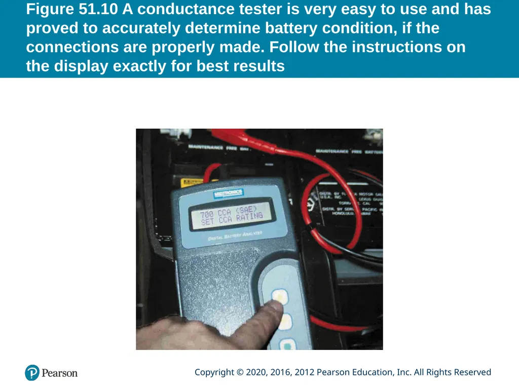
Figure 51.10 A conductance tester is very easy to use and has proved to accurately determine battery condition, if the connections are properly made. Follow the instructions on the display exactly for best results<br>
29
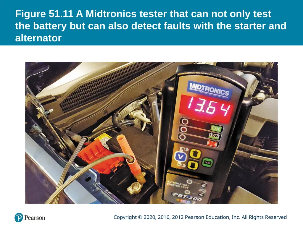
Figure 51.11 A Midtronics tester that can not only test the battery but can also detect faults with the starter and alternator<br>
30
BATTERY CHARGING Charging Procedure
Determine charge rate
Connect battery charger to battery
Plug in charger to outlet
Set the charging rate<br>
31
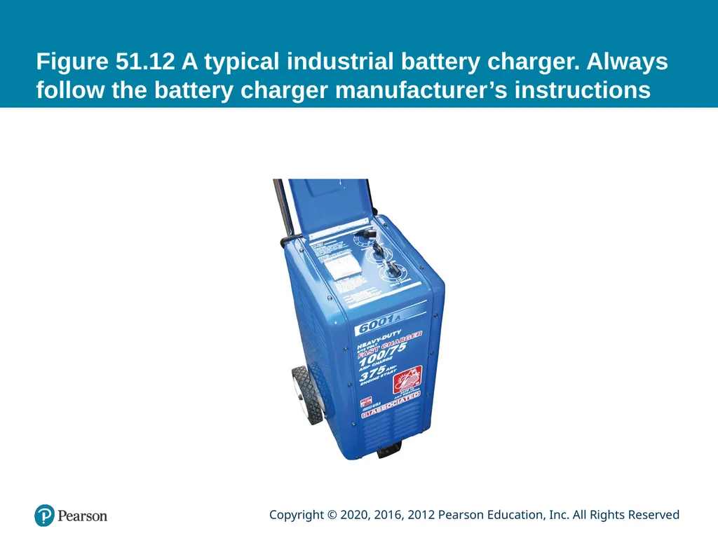
Figure 51.12 A typical industrial battery charger. Always follow the battery charger manufacturer’s instructions<br>
32
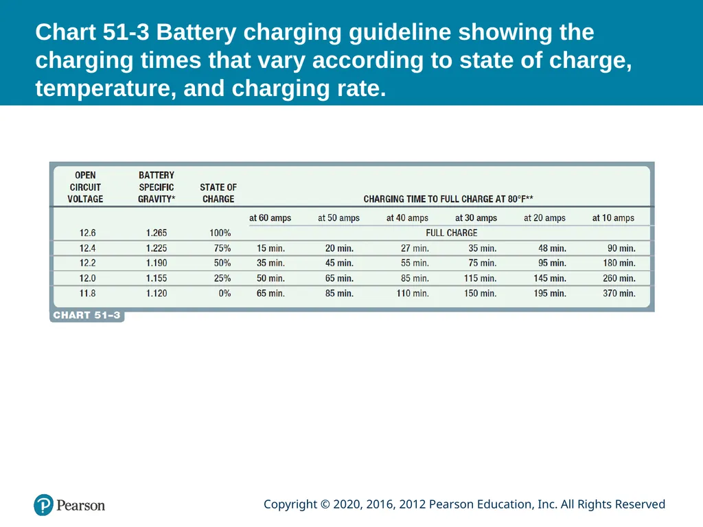
Chart 51-3 Battery charging guideline showing the charging times that vary according to state of charge, temperature, and charging rate.<br>
34
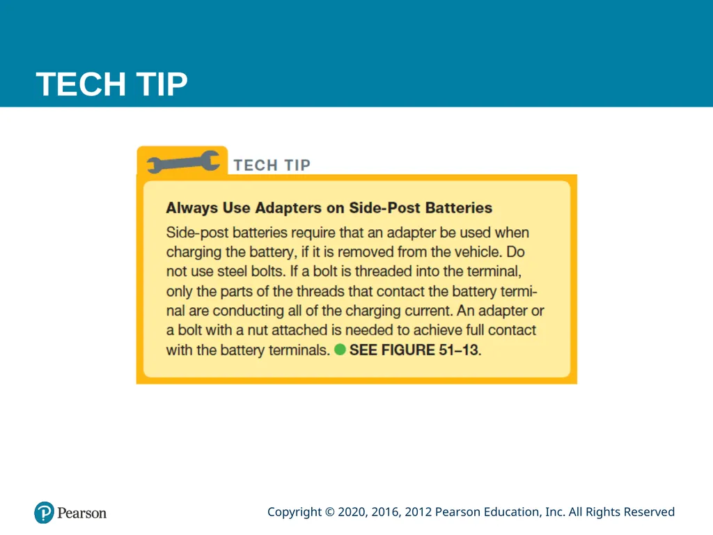
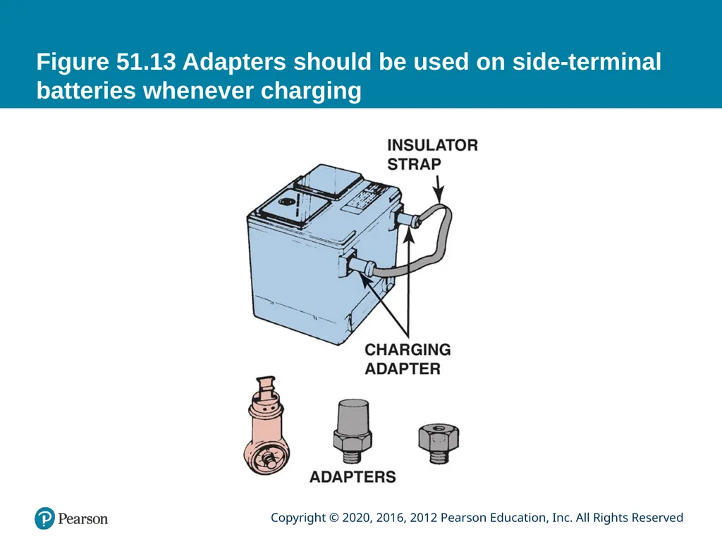
Figure 51.13 Adapters should be used on side-terminal batteries whenever charging<br>
35
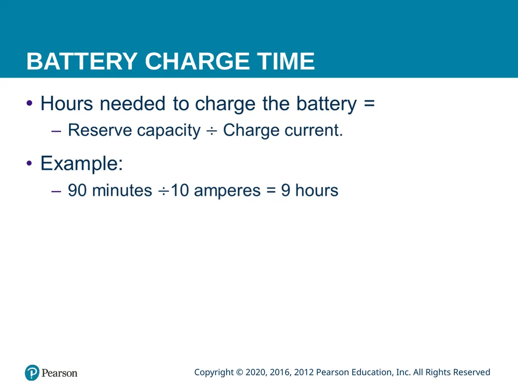
BATTERY CHARGE TIME<br>
36
JUMP STARTING When using jumper cables or a battery jump box, the last connection made should always be on the engine block or an engine bracket on the dead vehicle as far from the battery as possible.
Many newer vehicles have special ground and/or positive power connections built away from the battery just for the purpose of jump starting.<br>
37
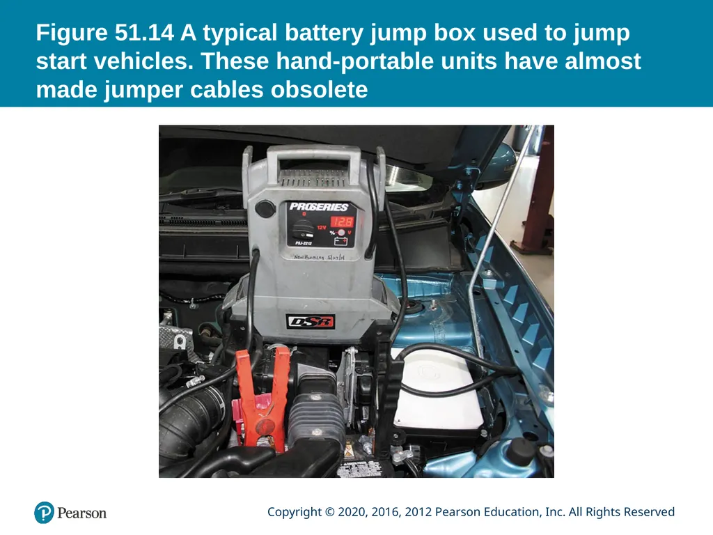
Figure 51.14 A typical battery jump box used to jump start vehicles. These hand-portable units have almost made jumper cables obsolete<br>
39
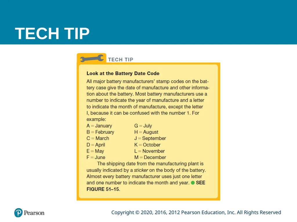
Figure 51.15 The sticker on this battery indicates that it was shipped from the factory January, 2015<br>
40
BATTERY ELECTRICAL DRAIN TESTING (1 OF 2) The battery electrical drain test determines if any component or circuit in a vehicle is causing a drain on the battery when everything is off.
Using an Inductive DC ammeter
The fastest and easiest method to measure battery electrical drain
Clamp around either cable
Capable of measuring low current (10 milliamperes)<br>
41
BATTERY ELECTRICAL DRAIN TESTING (2 OF 2) Using a DMM set to read milliamperes
Make certain that all lights, accessories, and ignition are off.
Disconnect the negative (-) battery cable and install a parasitic load tool.
Start the engine and drive the vehicle about 10 minutes.
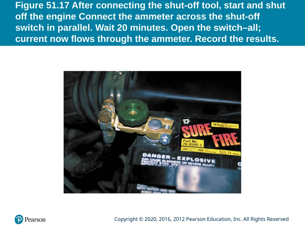
Connect an ammeter across the parasitic load tool switch and wait 20 minutes
Open the switch on the load tool and read the battery electrical drain on the meter display<br>
42
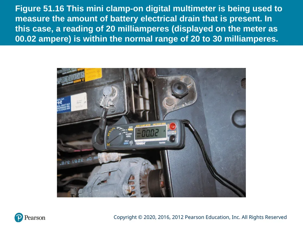
Figure 51.16 This mini clamp-on digital multimeter is being used to measure the amount of battery electrical drain that is present. In this case, a reading of 20 milliamperes (displayed on the meter as 00.02 ampere) is within the normal range of 20 to 30 milliamperes.<br>
43
Figure 51.17 After connecting the shut-off tool, start and shut off the engine Connect the ammeter across the shut-off switch in parallel. Wait 20 minutes. Open the switch–all; current now flows through the ammeter. Record the results.<br>
44
QUESTION 3: ? How is a battery drain test performed?<br>
45
ANSWER 3: With an inductive DC ammeter or a DMM set to read milliamperes.
.<br>
46
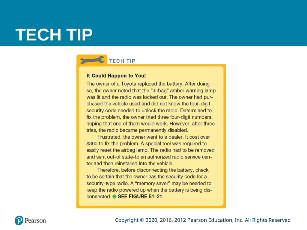
MAINTAINING ELECTRONIC MEMORY FUNCTIONS Disconnect Issues
Security system, PCM relearn, Windows/Sunroof
Maintaining Memory Methods
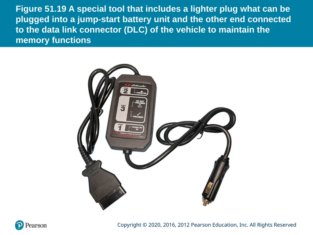
9 or 12 volt supply at DLC or Power Plug (lighter)
Re-initialization
Power windows, Radio antitheft, intelligent battery systems<br>
47
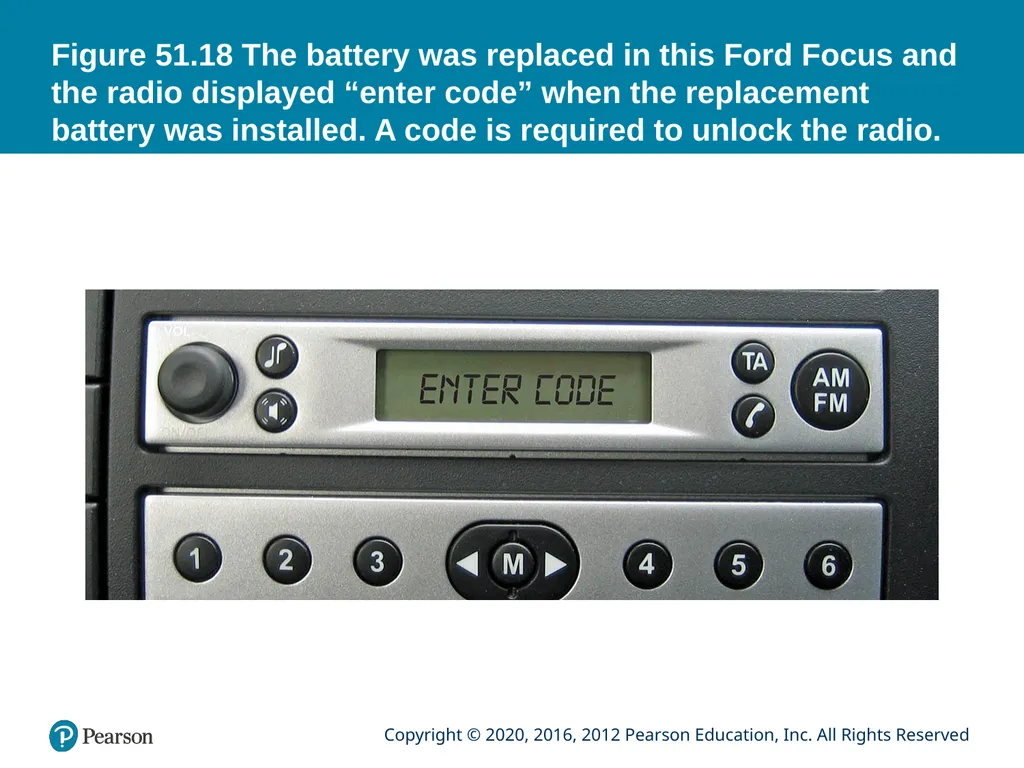
Figure 51.18 The battery was replaced in this Ford Focus and the radio displayed “enter code” when the replacement battery was installed. A code is required to unlock the radio.<br>
48
Figure 51.19 A special tool that includes a lighter plug what can be plugged into a jump-start battery unit and the other end connected to the data link connector (DLC) of the vehicle to maintain the memory functions<br>
49
Figure 51.20 A memory saver tool that uses a 12-volt battery to connect to the power (terminal 16) and ground (terminals 4 and 5) of the DLC<br>
51
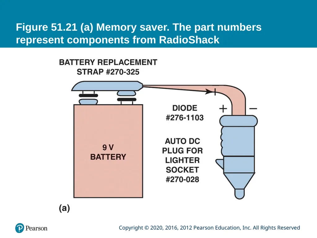
Figure 51.21 (a) Memory saver. The part numbers represent components from RadioShack<br>
52
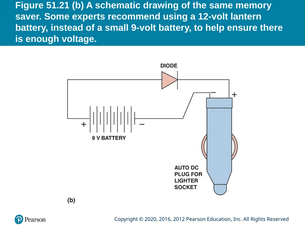
Figure 51.21 (b) A schematic drawing of the same memory saver. Some experts recommend using a 12-volt lantern battery, instead of a small 9-volt battery, to help ensure there is enough voltage.<br>
53
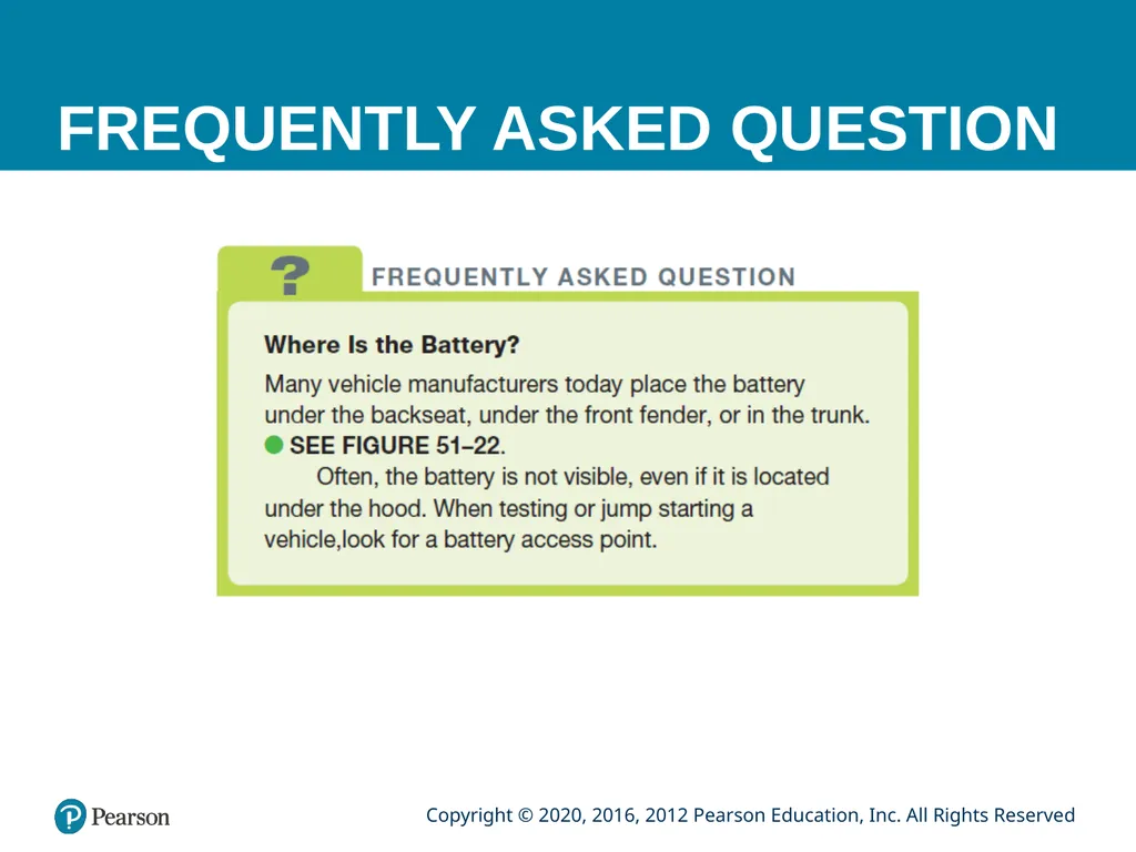
FREQUENTLY ASKED QUESTION<br>
54
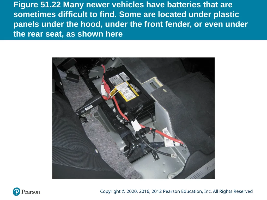
Figure 51.22 Many newer vehicles have batteries that are sometimes difficult to find. Some are located under plastic panels under the hood, under the front fender, or even under the rear seat, as shown here<br>