C H A P T E R 82 Dimensioning TERMINOLOGY
Description: C H A P T E R 82 Dimensioning TERMINOLOGY AND CONVENTIONS . Extension lines: Lines that extend away from an object and allow dimensions to be located off the surface of an object. Leader lines: Lines drawn at an angle, not horizontal or
Related Topics
Download Presentation
"C H A P T E R 82 Dimensioning TERMINOLOGY" is the property of its rightful owner. Permission is granted to download and print the materials on this website for personal, non-commercial use only, and to display it on your personal computer provided you do not modify the materials and that you retain all copyright notices contained in the materials. By downloading content from our website, you accept the terms of this agreement.
Presentation Transcript
slide1. C H A P T E R 82 Dimensioning<br>
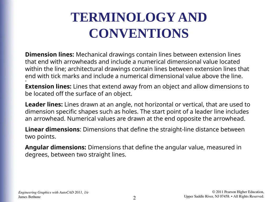
slide2. TERMINOLOGY ANDCONVENTIONS .
Extension lines: Lines that extend away from an object and allow dimensions to be located off the surface of an object.
Leader lines: Lines drawn at an angle, not horizontal or vertical, that are used to dimension specific shapes such as holes. The start point of a leader line includes an arrowhead. Numerical values are drawn at the end opposite the arrowhead.
Linear dimensions: Dimensions that define the straight-line distance between two points.
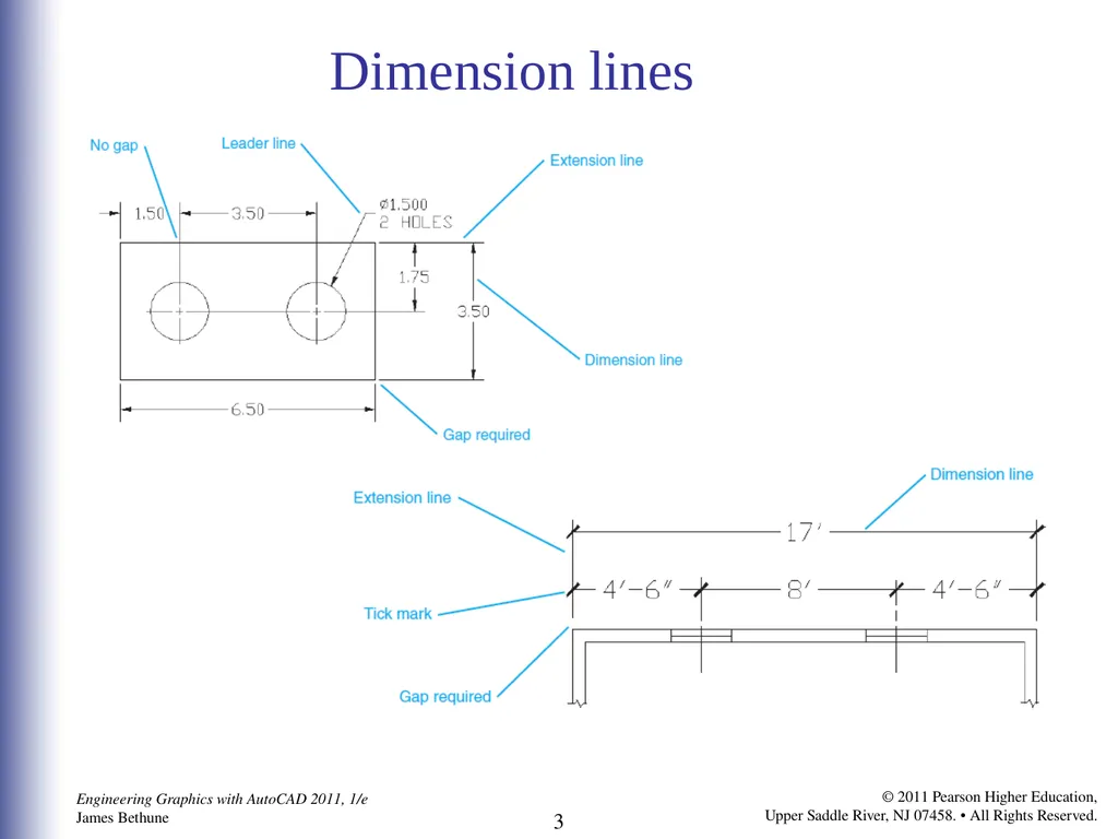
Angular dimensions: Dimensions that define the angular value, measured in degrees, between two straight lines. Dimension lines: Mechanical drawings contain lines between extension lines that end with arrowheads and include a numerical dimensional value located within the line; architectural drawings contain lines between extension lines that end with tick marks and include a numerical dimensional value above the line.<br>
slide3. Dimension lines<br>
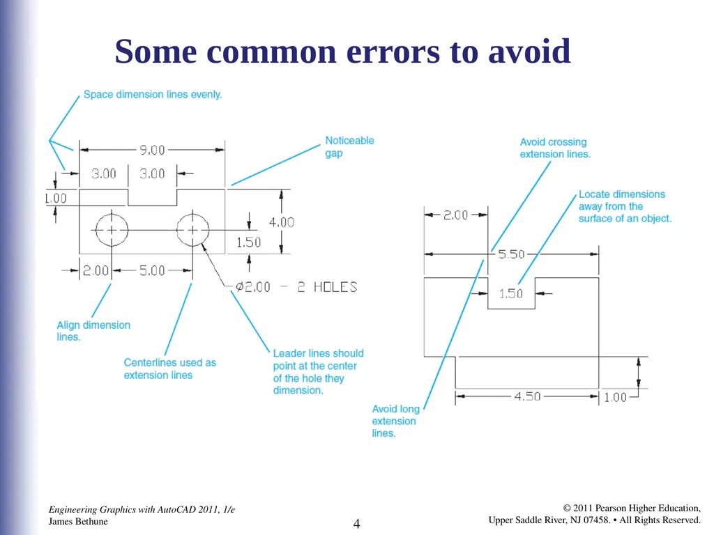
slide4. Some common errors to avoid<br>
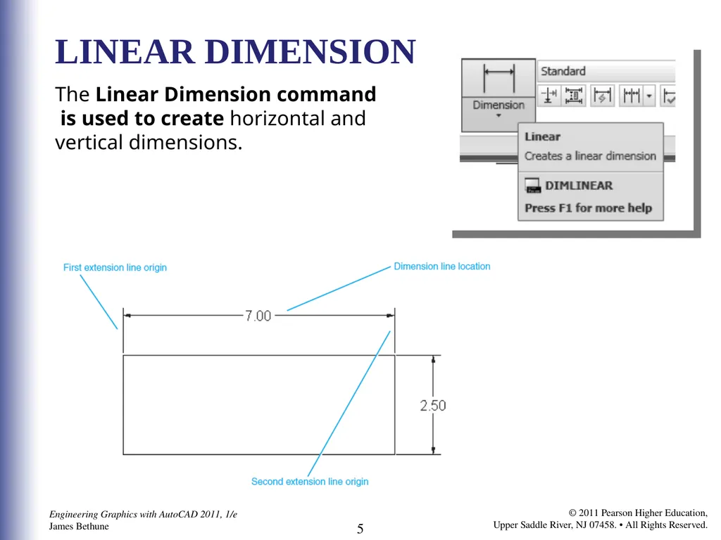
slide5. LINEAR DIMENSION The Linear Dimension command
is used to create horizontal and vertical dimensions.<br>
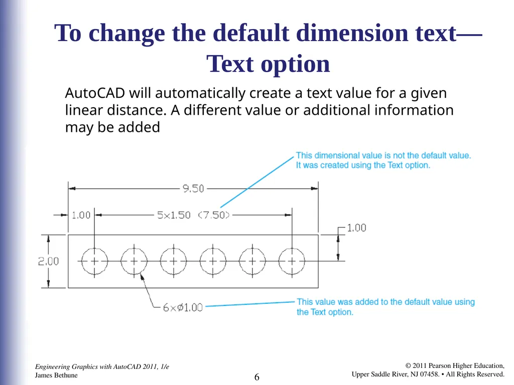
slide6. To change the default dimension text—Text option AutoCAD will automatically create a text value for a given linear distance. A different value or additional information
may be added<br>
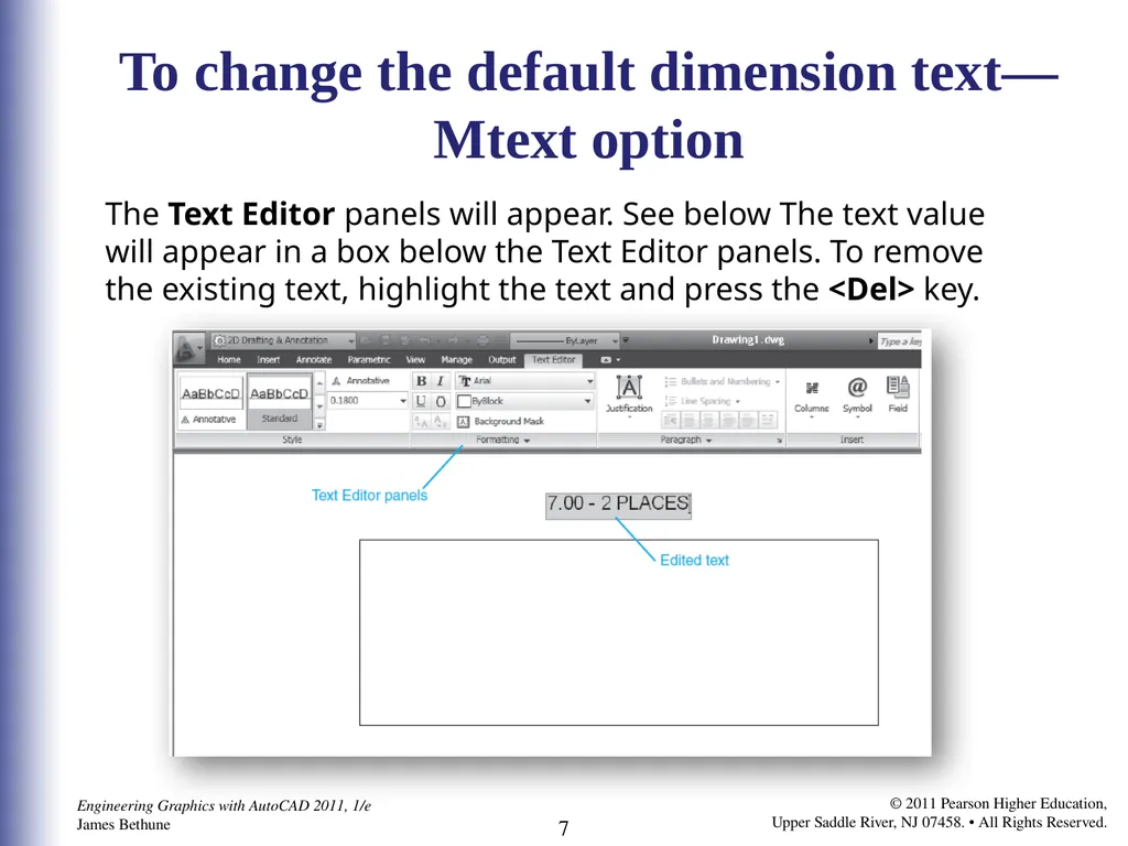
slide7. To change the default dimension text—Mtext option The Text Editor panels will appear. See below The text value will appear in a box below the Text Editor panels. To remove the existing text, highlight the text and press the <Del> key.<br>
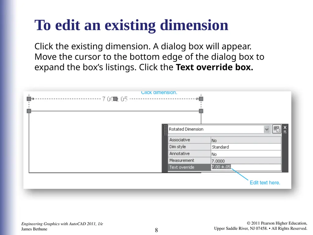
slide8. To edit an existing dimension Click the existing dimension. A dialog box will appear.
Move the cursor to the bottom edge of the dialog box to expand the box’s listings. Click the Text override box.<br>
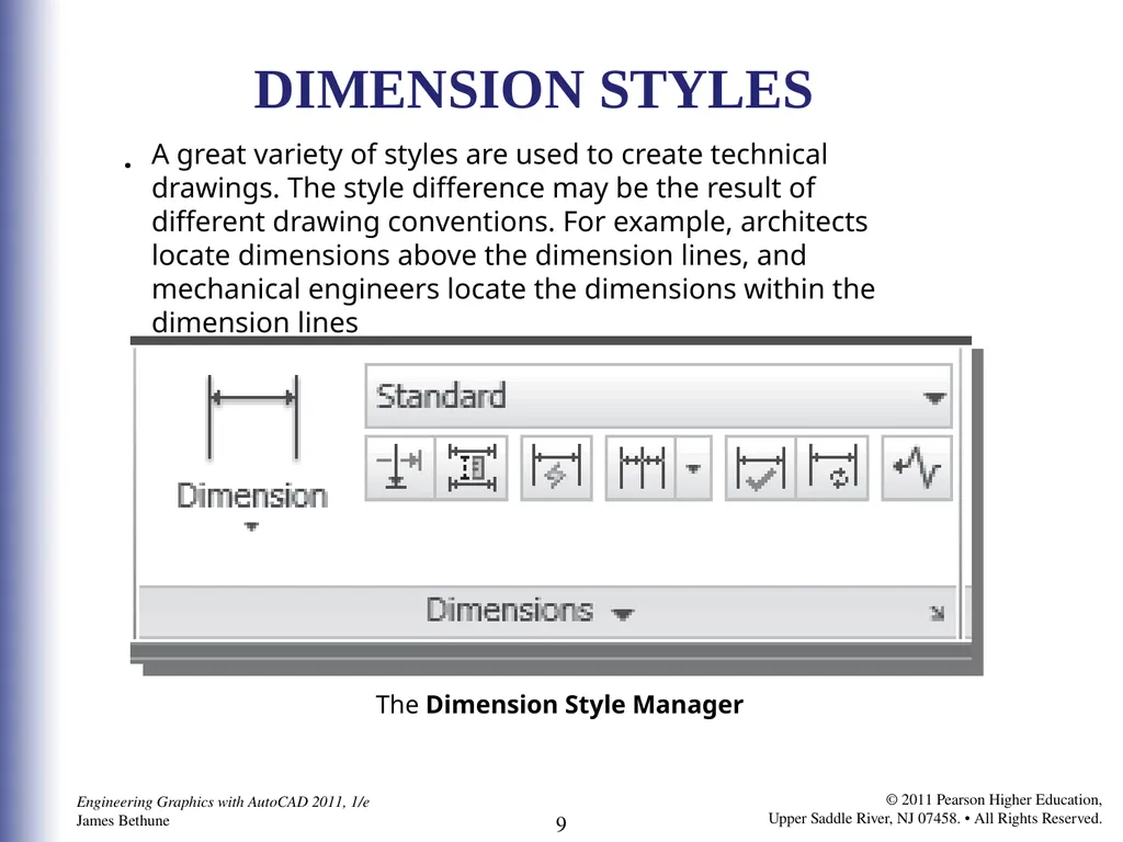
slide9. DIMENSION STYLES . A great variety of styles are used to create technical drawings. The style difference may be the result of different drawing conventions. For example, architects locate dimensions above the dimension lines, and mechanical engineers locate the dimensions within the dimension lines The Dimension Style Manager<br>
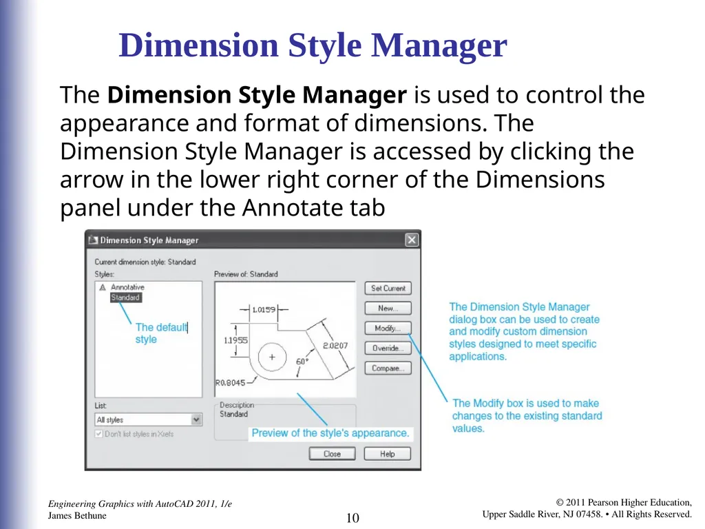
slide10. Dimension Style Manager The Dimension Style Manager is used to control the appearance and format of dimensions. The Dimension Style Manager is accessed by clicking the arrow in the lower right corner of the Dimensions panel under the Annotate tab<br>
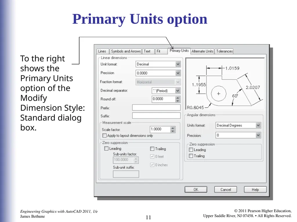
slide11. Primary Units option To the right shows the Primary Units option of the Modify Dimension Style: Standard dialog box.<br>
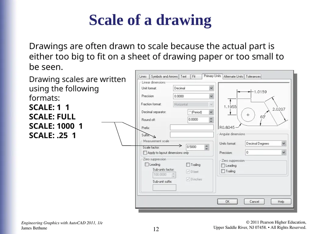
slide12. Scale of a drawing Drawings are often drawn to scale because the actual part is either too big to fit on a sheet of drawing paper or too small to be seen. Drawing scales are written
using the following formats:
SCALE: 1 1
SCALE: FULL
SCALE: 1000 1
SCALE: .25 1<br>
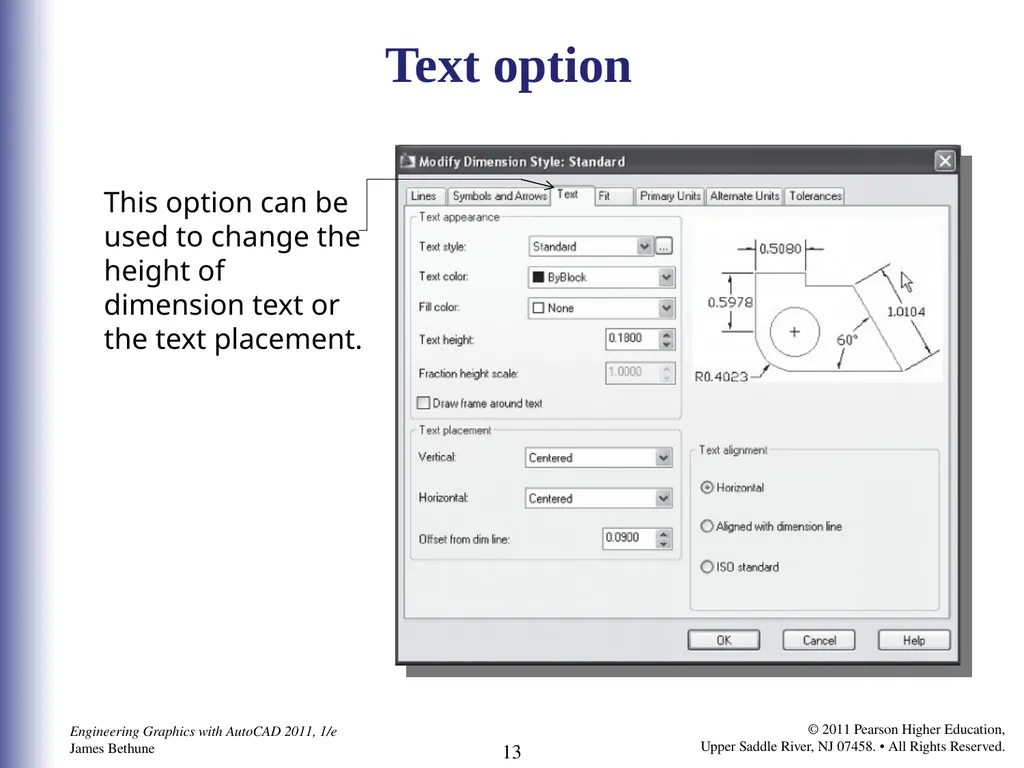
slide13. Text option This option can be
used to change the height of dimension text or the text placement.<br>
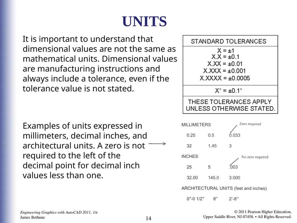
slide14. UNITS It is important to understand that dimensional values are not the same as mathematical units. Dimensional values are manufacturing instructions and always include a tolerance, even if the tolerance value is not stated. Examples of units expressed in millimeters, decimal inches, and architectural units. A zero is not required to the left of the decimal point for decimal inch values less than one.<br>
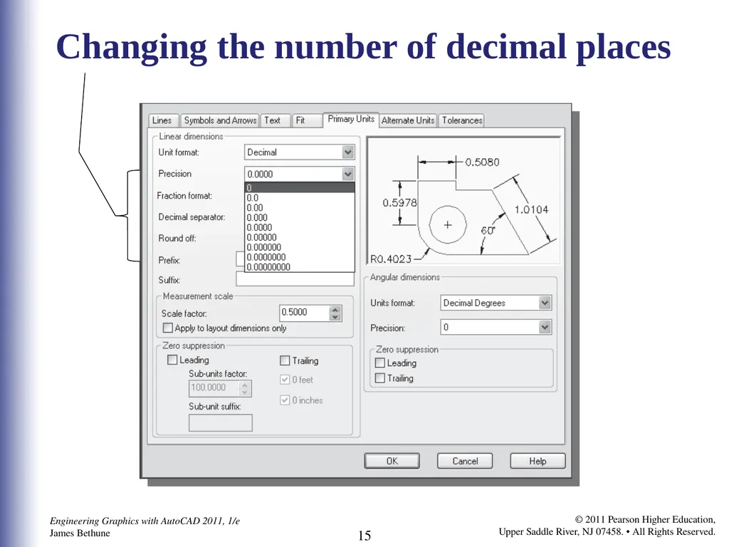
slide15. Changing the number of decimal places<br>
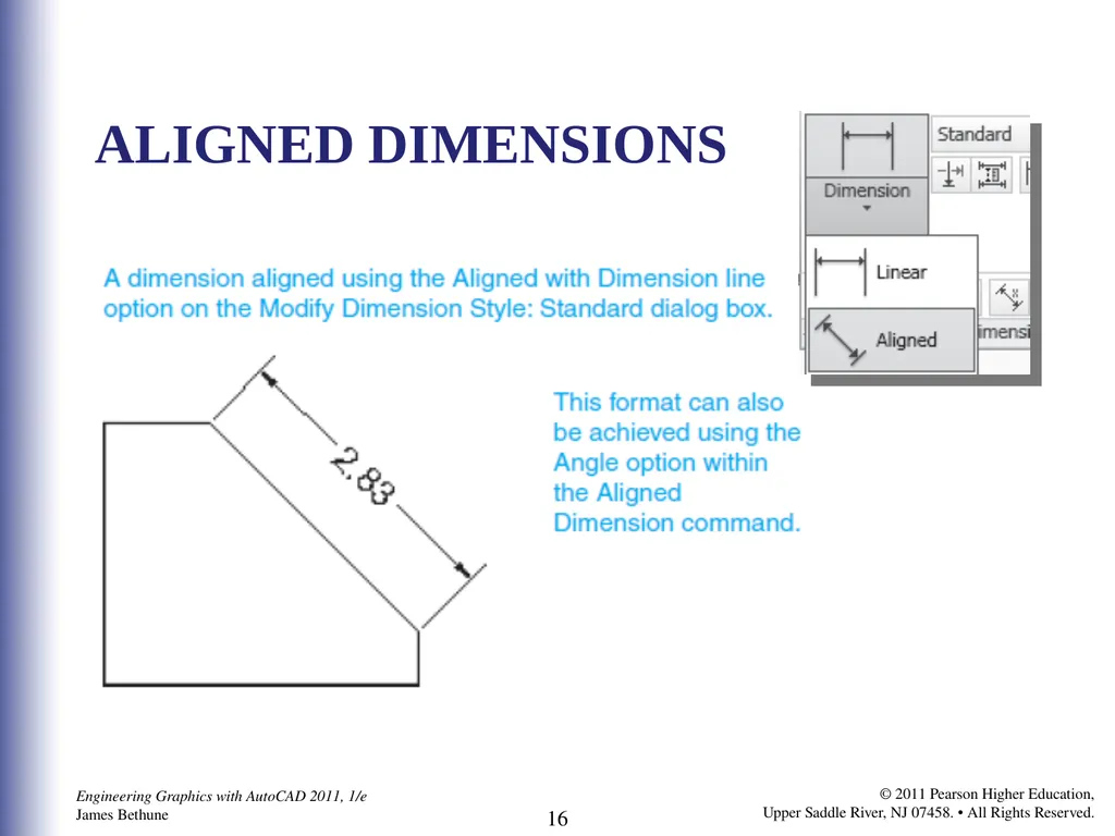
slide16. ALIGNED DIMENSIONS<br>
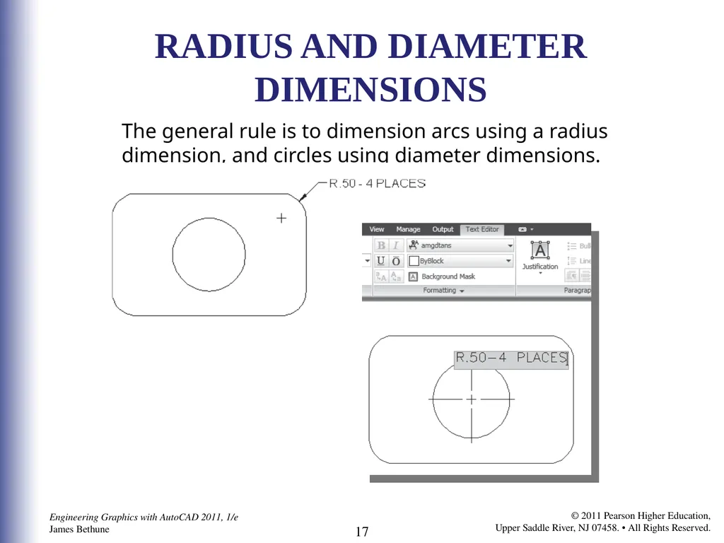
slide17. RADIUS AND DIAMETERDIMENSIONS The general rule is to dimension arcs using a radius
dimension, and circles using diameter dimensions.<br>
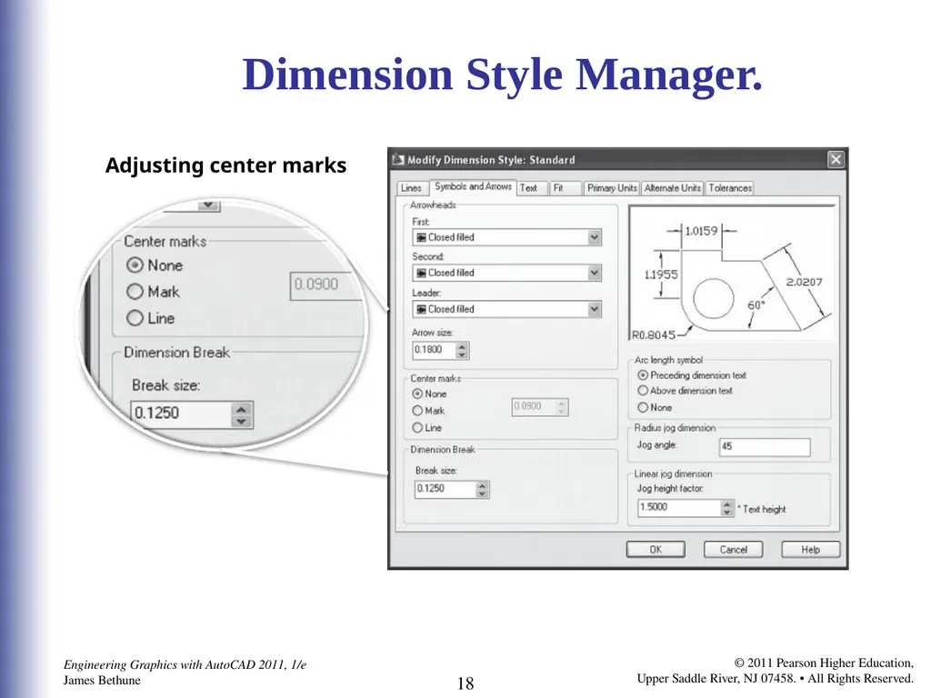
slide18. Dimension Style Manager. Adjusting center marks<br>
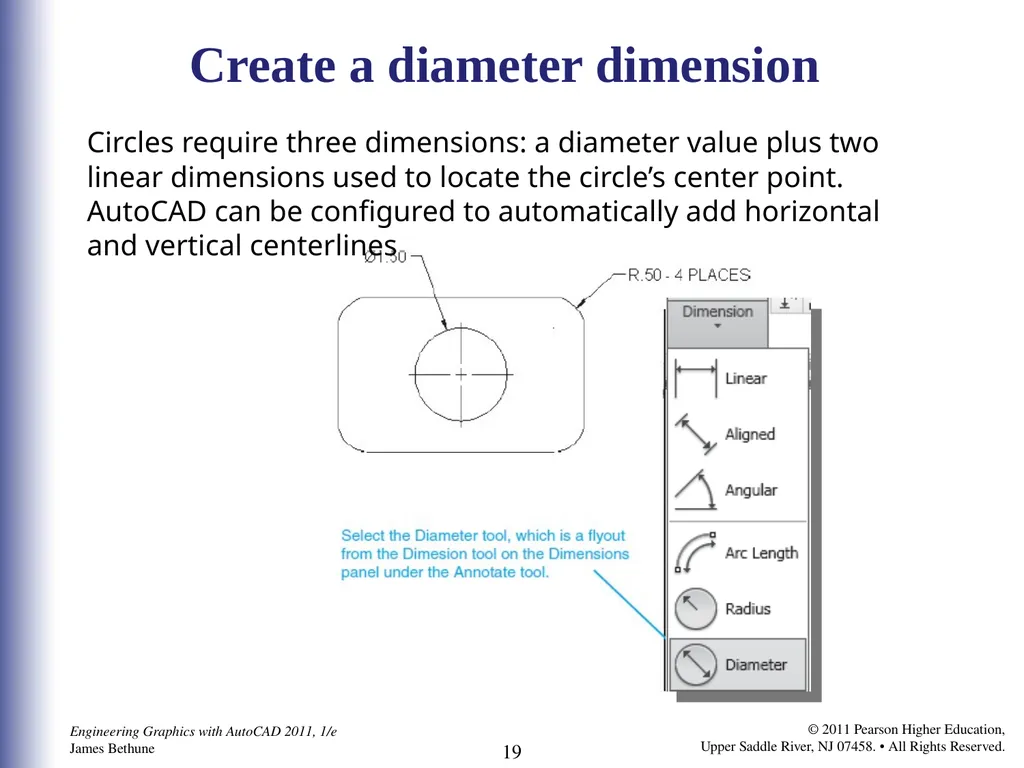
slide19. Create a diameter dimension Circles require three dimensions: a diameter value plus two linear dimensions used to locate the circle’s center point. AutoCAD can be configured to automatically add horizontal and vertical centerlines<br>
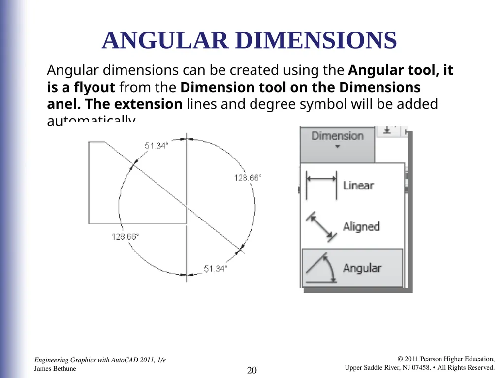
slide20. ANGULAR DIMENSIONS Angular dimensions can be created using the Angular tool, it is a flyout from the Dimension tool on the Dimensions anel. The extension lines and degree symbol will be added automatically.<br>
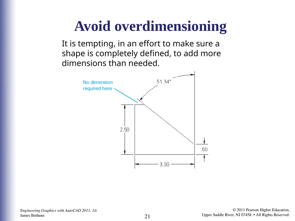
slide21. Avoid overdimensioning It is tempting, in an effort to make sure a shape is completely defined, to add more dimensions than needed.<br>
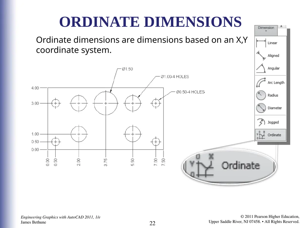
slide22. ORDINATE DIMENSIONS Ordinate dimensions are dimensions based on an X,Y coordinate system.<br>
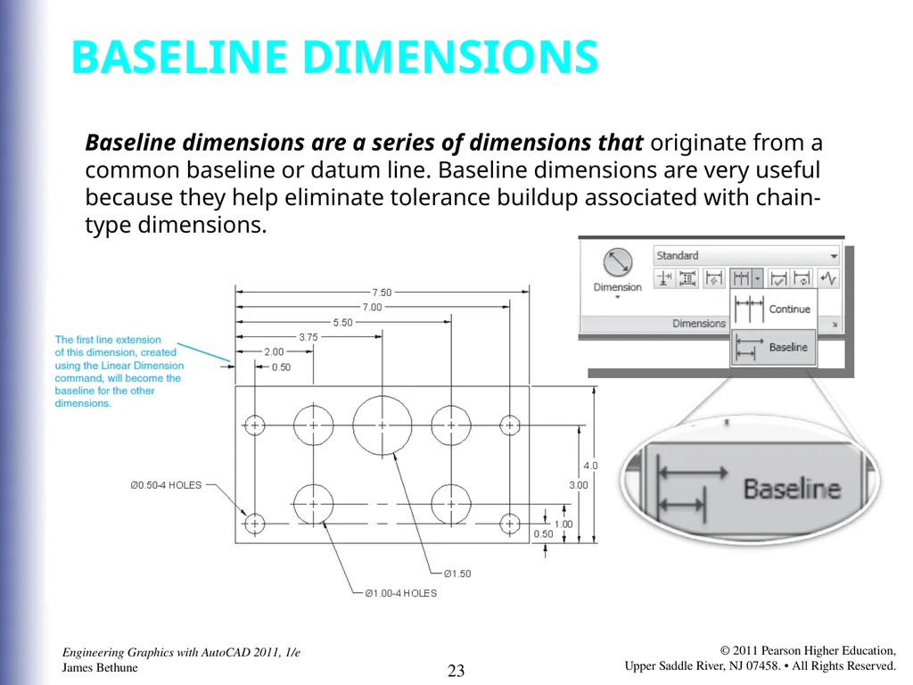
slide23. BASELINE DIMENSIONS Baseline dimensions are a series of dimensions that originate from a common baseline or datum line. Baseline dimensions are very useful because they help eliminate tolerance buildup associated with chain-type dimensions.<br>
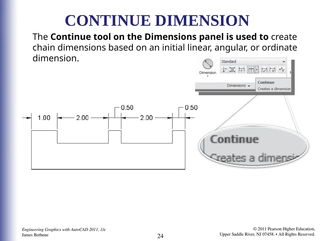
slide24. CONTINUE DIMENSION The Continue tool on the Dimensions panel is used to create chain dimensions based on an initial linear, angular, or ordinate dimension.<br>
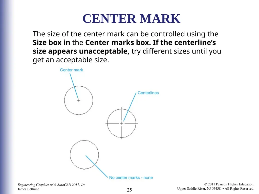
slide25. CENTER MARK The size of the center mark can be controlled using the Size box in the Center marks box. If the centerline’s size appears unacceptable, try different sizes until you get an acceptable size.<br>
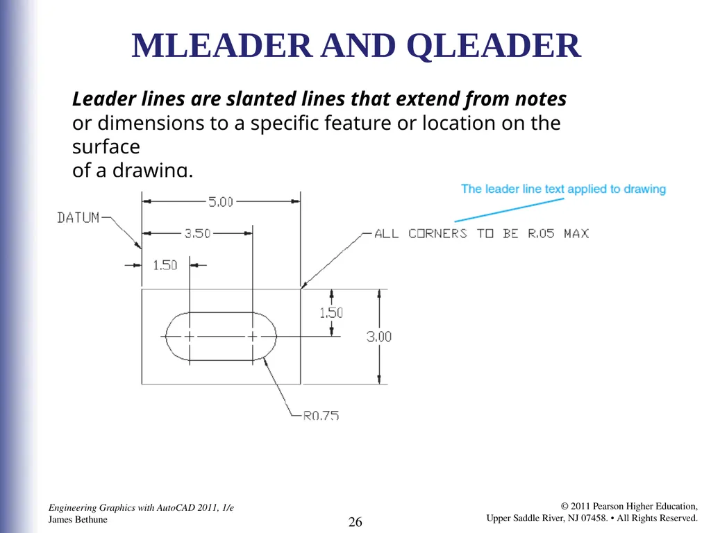
slide26. MLEADER AND QLEADER Leader lines are slanted lines that extend from notes
or dimensions to a specific feature or location on the surface
of a drawing.<br>
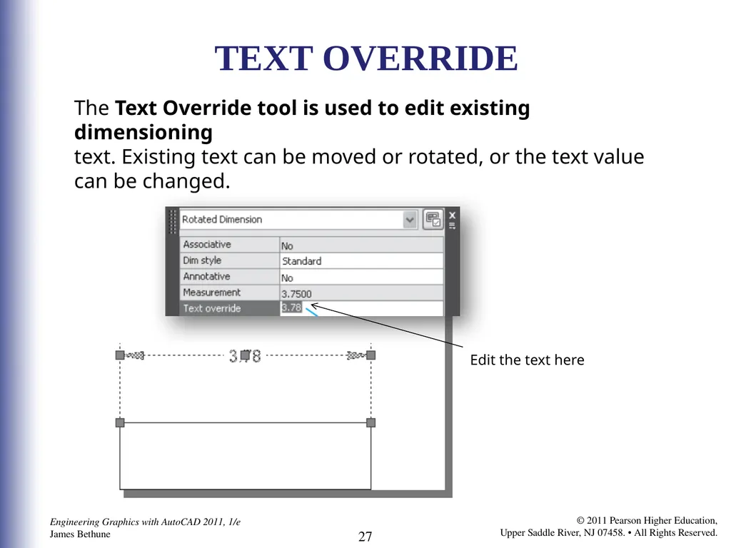
slide27. TEXT OVERRIDE The Text Override tool is used to edit existing dimensioning
text. Existing text can be moved or rotated, or the text value can be changed. Edit the text here<br>
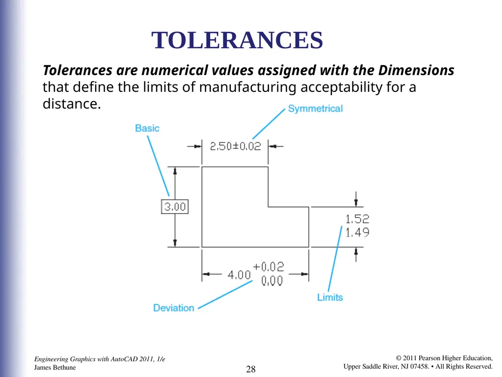
slide28. TOLERANCES Tolerances are numerical values assigned with the Dimensions that define the limits of manufacturing acceptability for a distance.<br>
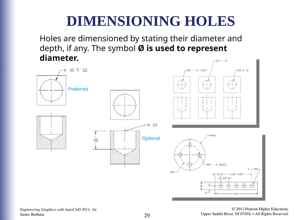
slide29. DIMENSIONING HOLES Holes are dimensioned by stating their diameter and
depth, if any. The symbol Ø is used to represent diameter.<br>
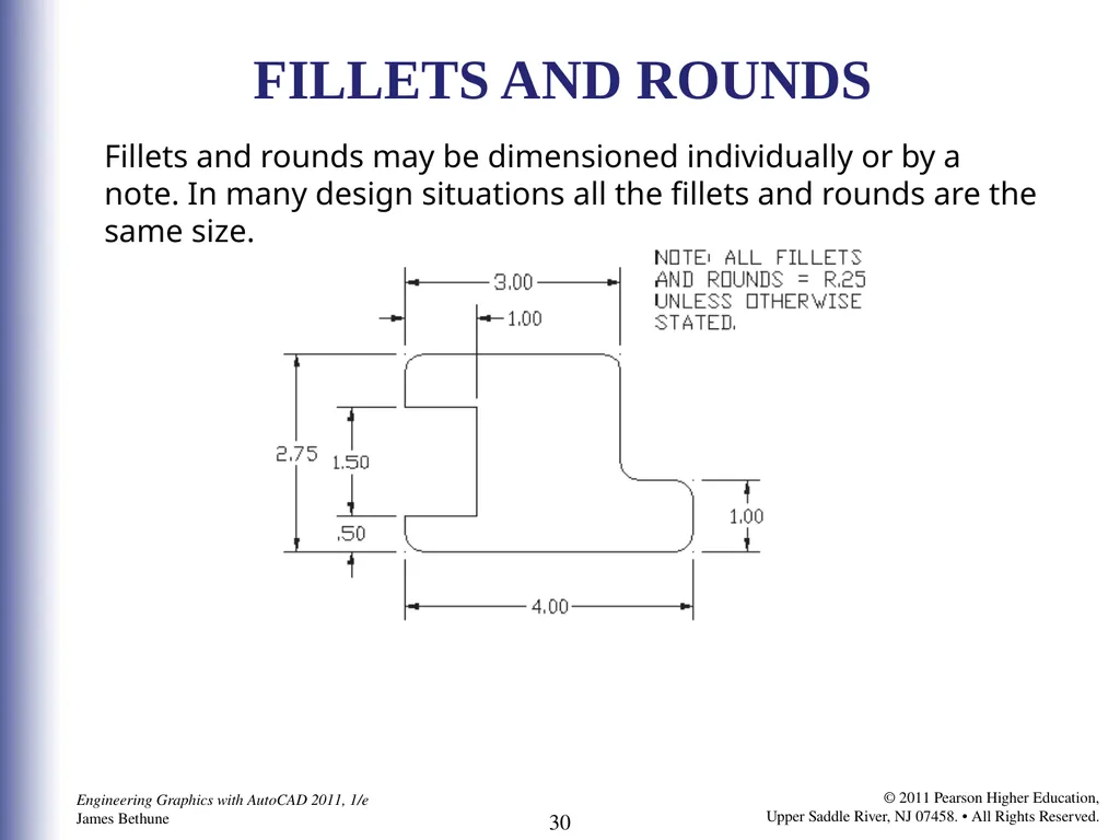
slide30. FILLETS AND ROUNDS Fillets and rounds may be dimensioned individually or by a note. In many design situations all the fillets and rounds are the same size.<br>
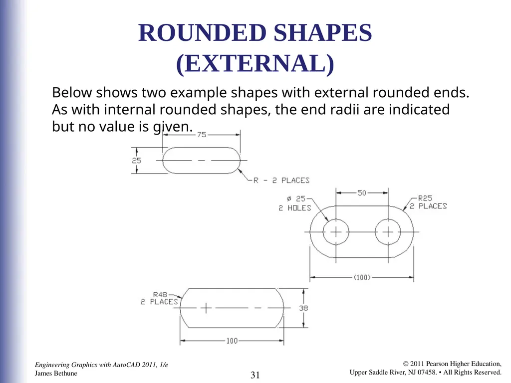
slide31. ROUNDED SHAPES(EXTERNAL) Below shows two example shapes with external rounded ends. As with internal rounded shapes, the end radii are indicated but no value is given.<br>
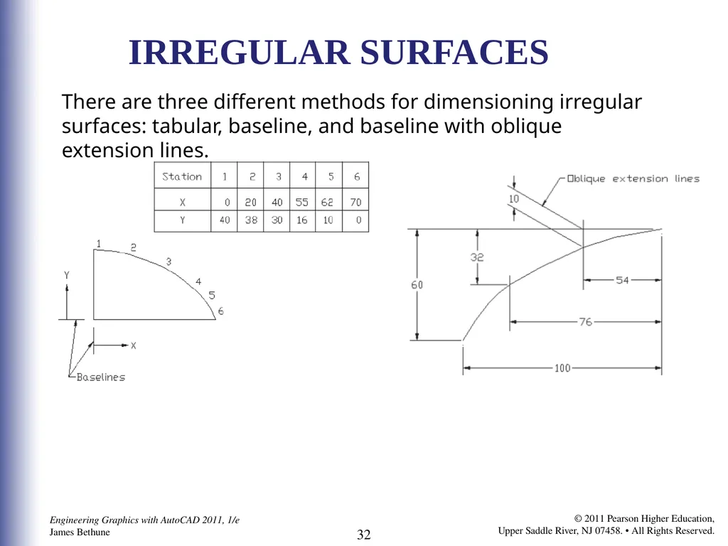
slide32. IRREGULAR SURFACES There are three different methods for dimensioning irregular
surfaces: tabular, baseline, and baseline with oblique extension lines.<br>
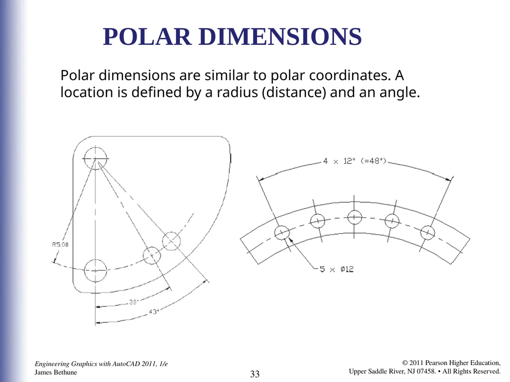
slide33. POLAR DIMENSIONS Polar dimensions are similar to polar coordinates. A location is defined by a radius (distance) and an angle.<br>
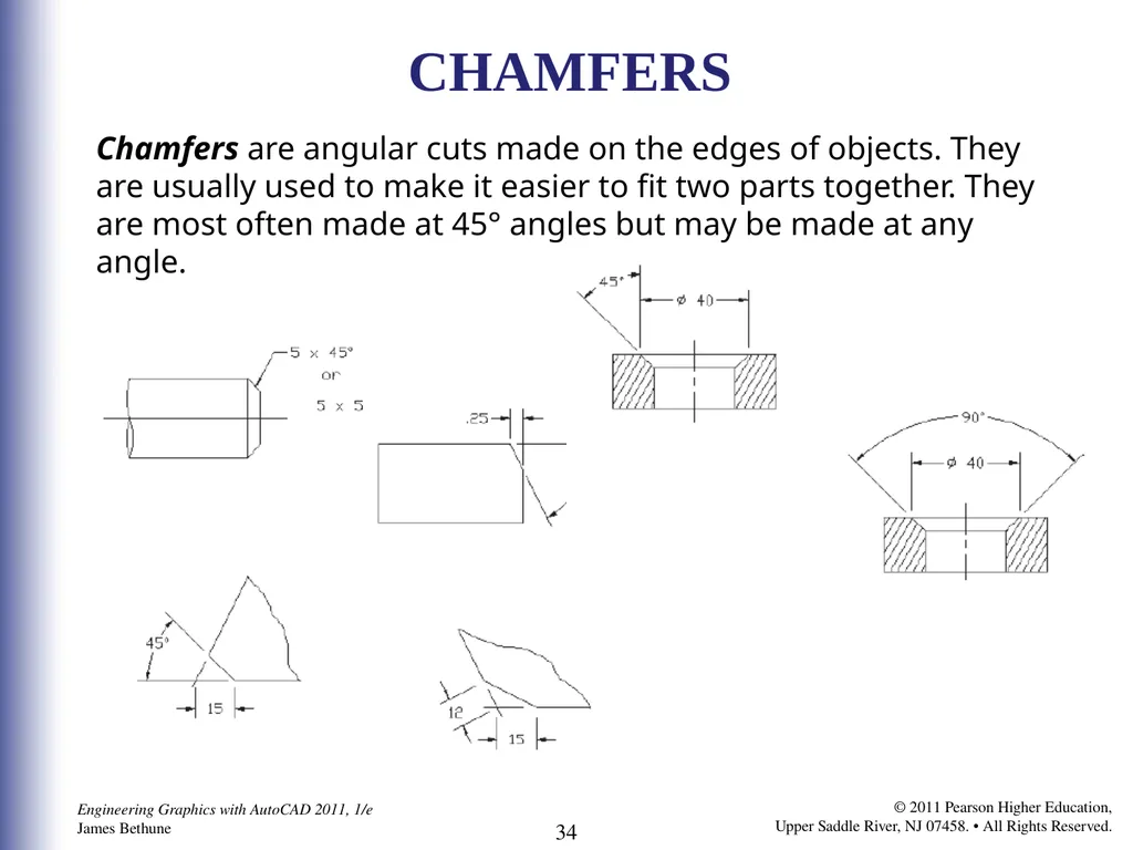
slide34. CHAMFERS Chamfers are angular cuts made on the edges of objects. They are usually used to make it easier to fit two parts together. They are most often made at 45° angles but may be made at any angle.<br>
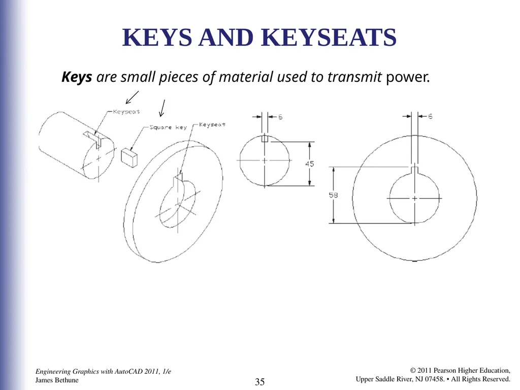
slide35. KEYS AND KEYSEATS Keys are small pieces of material used to transmit power.<br>
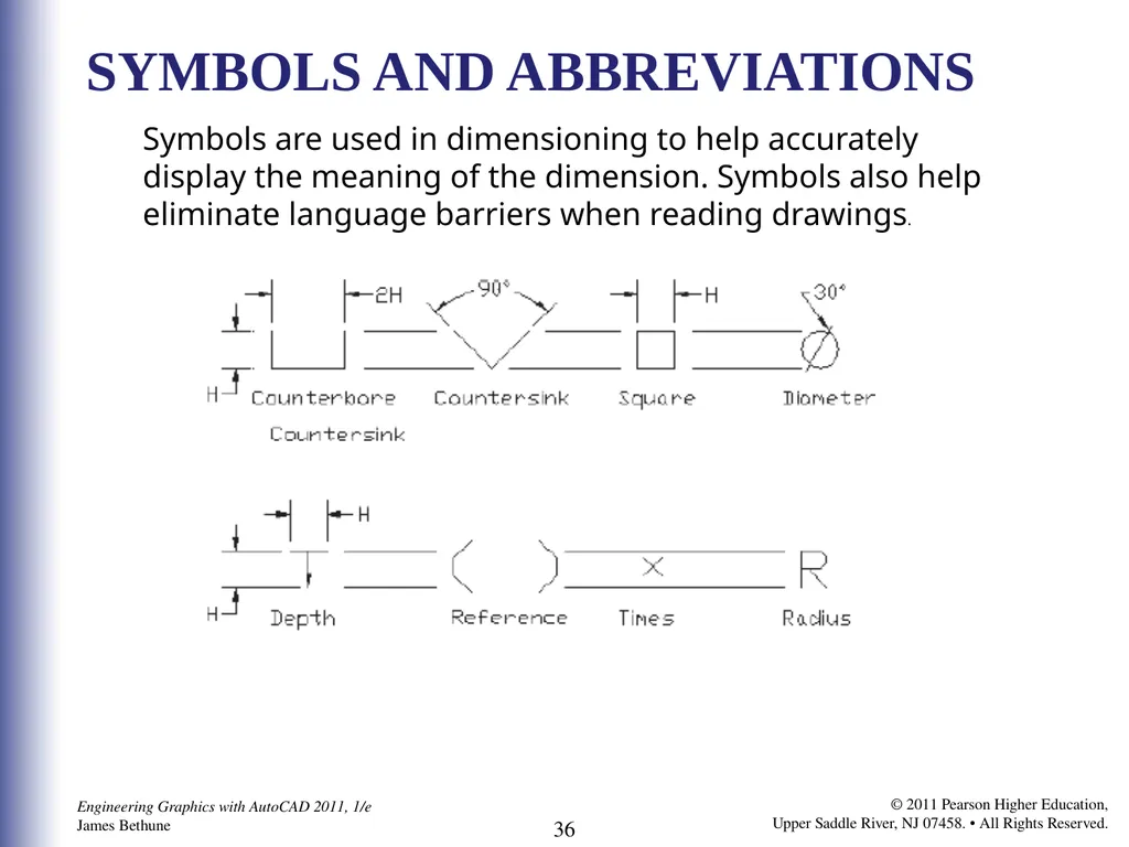
slide36. SYMBOLS AND ABBREVIATIONS Symbols are used in dimensioning to help accurately display the meaning of the dimension. Symbols also help eliminate language barriers when reading drawings.<br>
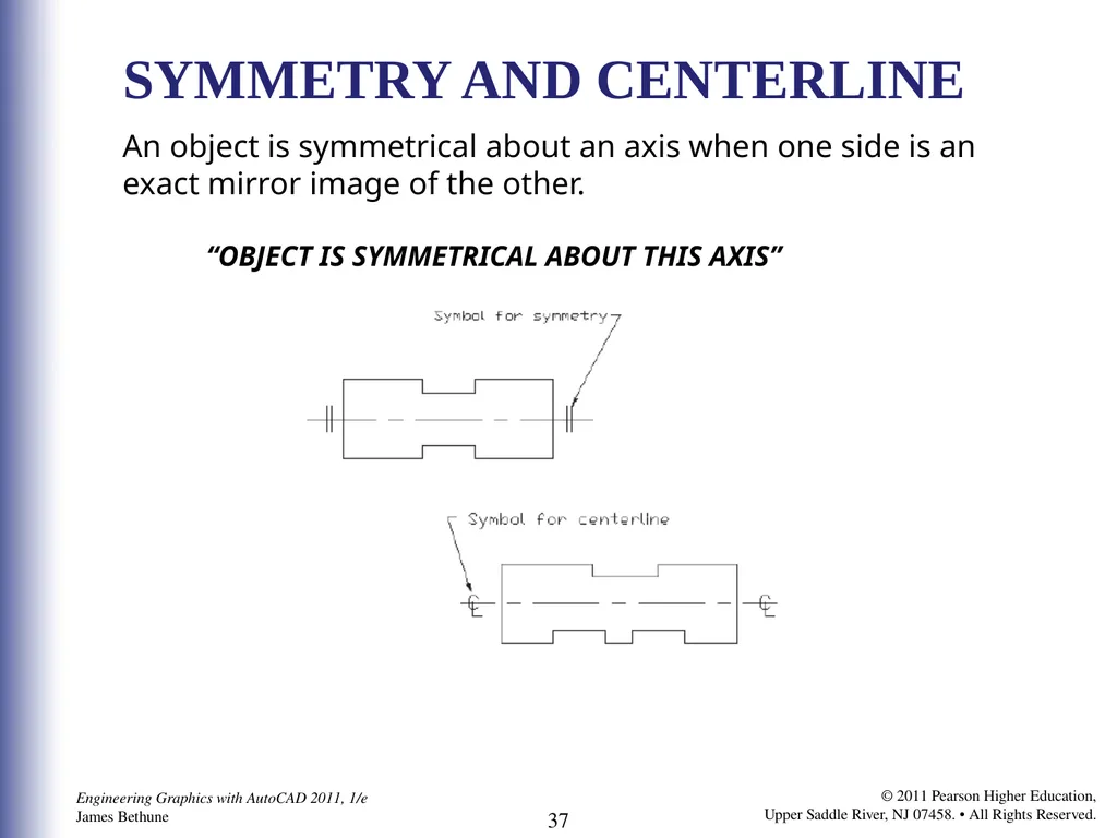
slide37. SYMMETRY AND CENTERLINE “OBJECT IS SYMMETRICAL ABOUT THIS AXIS” An object is symmetrical about an axis when one side is an exact mirror image of the other.<br>
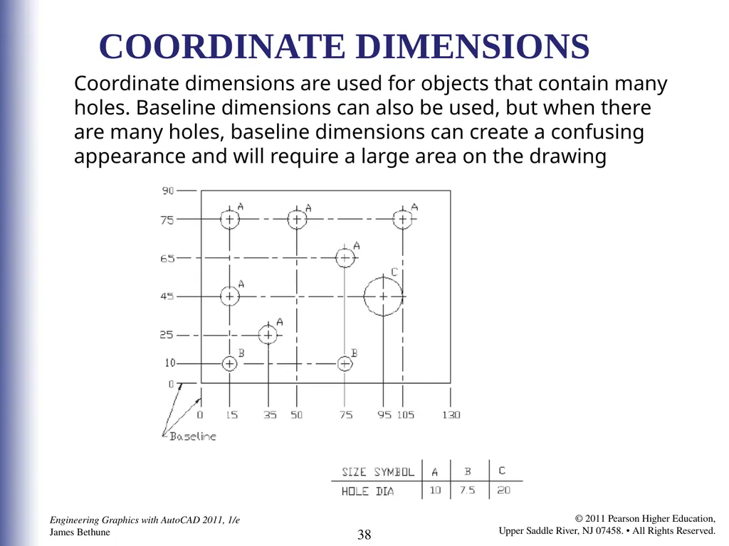
slide38. COORDINATE DIMENSIONS Coordinate dimensions are used for objects that contain many holes. Baseline dimensions can also be used, but when there are many holes, baseline dimensions can create a confusing appearance and will require a large area on the drawing<br>
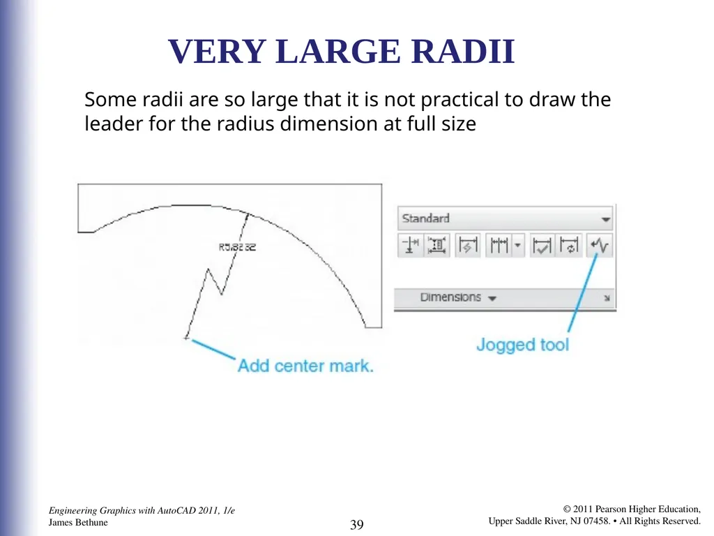
slide39. VERY LARGE RADII Some radii are so large that it is not practical to draw the
leader for the radius dimension at full size<br>

slide2. TERMINOLOGY ANDCONVENTIONS .
Extension lines: Lines that extend away from an object and allow dimensions to be located off the surface of an object.
Leader lines: Lines drawn at an angle, not horizontal or vertical, that are used to dimension specific shapes such as holes. The start point of a leader line includes an arrowhead. Numerical values are drawn at the end opposite the arrowhead.
Linear dimensions: Dimensions that define the straight-line distance between two points.
Angular dimensions: Dimensions that define the angular value, measured in degrees, between two straight lines. Dimension lines: Mechanical drawings contain lines between extension lines that end with arrowheads and include a numerical dimensional value located within the line; architectural drawings contain lines between extension lines that end with tick marks and include a numerical dimensional value above the line.<br>
slide3. Dimension lines<br>
slide4. Some common errors to avoid<br>
slide5. LINEAR DIMENSION The Linear Dimension command
is used to create horizontal and vertical dimensions.<br>
slide6. To change the default dimension text—Text option AutoCAD will automatically create a text value for a given linear distance. A different value or additional information
may be added<br>
slide7. To change the default dimension text—Mtext option The Text Editor panels will appear. See below The text value will appear in a box below the Text Editor panels. To remove the existing text, highlight the text and press the <Del> key.<br>
slide8. To edit an existing dimension Click the existing dimension. A dialog box will appear.
Move the cursor to the bottom edge of the dialog box to expand the box’s listings. Click the Text override box.<br>
slide9. DIMENSION STYLES . A great variety of styles are used to create technical drawings. The style difference may be the result of different drawing conventions. For example, architects locate dimensions above the dimension lines, and mechanical engineers locate the dimensions within the dimension lines The Dimension Style Manager<br>
slide10. Dimension Style Manager The Dimension Style Manager is used to control the appearance and format of dimensions. The Dimension Style Manager is accessed by clicking the arrow in the lower right corner of the Dimensions panel under the Annotate tab<br>
slide11. Primary Units option To the right shows the Primary Units option of the Modify Dimension Style: Standard dialog box.<br>
slide12. Scale of a drawing Drawings are often drawn to scale because the actual part is either too big to fit on a sheet of drawing paper or too small to be seen. Drawing scales are written
using the following formats:
SCALE: 1 1
SCALE: FULL
SCALE: 1000 1
SCALE: .25 1<br>
slide13. Text option This option can be
used to change the height of dimension text or the text placement.<br>
slide14. UNITS It is important to understand that dimensional values are not the same as mathematical units. Dimensional values are manufacturing instructions and always include a tolerance, even if the tolerance value is not stated. Examples of units expressed in millimeters, decimal inches, and architectural units. A zero is not required to the left of the decimal point for decimal inch values less than one.<br>
slide15. Changing the number of decimal places<br>
slide16. ALIGNED DIMENSIONS<br>
slide17. RADIUS AND DIAMETERDIMENSIONS The general rule is to dimension arcs using a radius
dimension, and circles using diameter dimensions.<br>
slide18. Dimension Style Manager. Adjusting center marks<br>
slide19. Create a diameter dimension Circles require three dimensions: a diameter value plus two linear dimensions used to locate the circle’s center point. AutoCAD can be configured to automatically add horizontal and vertical centerlines<br>
slide20. ANGULAR DIMENSIONS Angular dimensions can be created using the Angular tool, it is a flyout from the Dimension tool on the Dimensions anel. The extension lines and degree symbol will be added automatically.<br>
slide21. Avoid overdimensioning It is tempting, in an effort to make sure a shape is completely defined, to add more dimensions than needed.<br>
slide22. ORDINATE DIMENSIONS Ordinate dimensions are dimensions based on an X,Y coordinate system.<br>
slide23. BASELINE DIMENSIONS Baseline dimensions are a series of dimensions that originate from a common baseline or datum line. Baseline dimensions are very useful because they help eliminate tolerance buildup associated with chain-type dimensions.<br>
slide24. CONTINUE DIMENSION The Continue tool on the Dimensions panel is used to create chain dimensions based on an initial linear, angular, or ordinate dimension.<br>
slide25. CENTER MARK The size of the center mark can be controlled using the Size box in the Center marks box. If the centerline’s size appears unacceptable, try different sizes until you get an acceptable size.<br>
slide26. MLEADER AND QLEADER Leader lines are slanted lines that extend from notes
or dimensions to a specific feature or location on the surface
of a drawing.<br>
slide27. TEXT OVERRIDE The Text Override tool is used to edit existing dimensioning
text. Existing text can be moved or rotated, or the text value can be changed. Edit the text here<br>
slide28. TOLERANCES Tolerances are numerical values assigned with the Dimensions that define the limits of manufacturing acceptability for a distance.<br>
slide29. DIMENSIONING HOLES Holes are dimensioned by stating their diameter and
depth, if any. The symbol Ø is used to represent diameter.<br>
slide30. FILLETS AND ROUNDS Fillets and rounds may be dimensioned individually or by a note. In many design situations all the fillets and rounds are the same size.<br>
slide31. ROUNDED SHAPES(EXTERNAL) Below shows two example shapes with external rounded ends. As with internal rounded shapes, the end radii are indicated but no value is given.<br>
slide32. IRREGULAR SURFACES There are three different methods for dimensioning irregular
surfaces: tabular, baseline, and baseline with oblique extension lines.<br>
slide33. POLAR DIMENSIONS Polar dimensions are similar to polar coordinates. A location is defined by a radius (distance) and an angle.<br>
slide34. CHAMFERS Chamfers are angular cuts made on the edges of objects. They are usually used to make it easier to fit two parts together. They are most often made at 45° angles but may be made at any angle.<br>
slide35. KEYS AND KEYSEATS Keys are small pieces of material used to transmit power.<br>
slide36. SYMBOLS AND ABBREVIATIONS Symbols are used in dimensioning to help accurately display the meaning of the dimension. Symbols also help eliminate language barriers when reading drawings.<br>
slide37. SYMMETRY AND CENTERLINE “OBJECT IS SYMMETRICAL ABOUT THIS AXIS” An object is symmetrical about an axis when one side is an exact mirror image of the other.<br>
slide38. COORDINATE DIMENSIONS Coordinate dimensions are used for objects that contain many holes. Baseline dimensions can also be used, but when there are many holes, baseline dimensions can create a confusing appearance and will require a large area on the drawing<br>
slide39. VERY LARGE RADII Some radii are so large that it is not practical to draw the
leader for the radius dimension at full size<br>