
Chapter 18: Testing, Maintaining, and



Description: Chapter 18: Testing, Maintaining, and Troubleshooting Aerial and Tiller Apparatus Knowledge Objectives Describe the routine tests, inspections, and servicing functions, for a given fire departments aerial apparatus and tiller apparatus.
Related Topics
Download Presentation
"Chapter 18: Testing, Maintaining, and" is the property of its rightful owner. Permission is granted to download and print the materials on this website for personal, non-commercial use only, and to display it on your personal computer provided you do not modify the materials and that you retain all copyright notices contained in the materials. By downloading content from our website, you accept the terms of this agreement.
Presentation Transcript
slide1. Chapter 18: Testing, Maintaining, and Troubleshooting Aerial and Tiller Apparatus<br>
slide2. Knowledge Objectives Describe the routine tests, inspections, and servicing functions, for a given fire department’s aerial apparatus and tiller apparatus.
Describe the routine tests, inspections, and servicing functions, for a given fire department’s aerial apparatus and tiller apparatus, according to the manufacturer’s specifications and requirements, and the policies and procedures of the jurisdiction.<br>
slide3. Knowledge Objectives Describe the aerial device inspection requirements and process for cable systems (if applicable).
Describe the aerial device inspection requirements and process for aerial device hydraulic systems.
Describe the aerial device inspection requirements and process for slides and rollers.<br>
slide4. Knowledge Objectives Describe the aerial device inspection requirements and process for stabilizing systems.
Describe the aerial device inspection requirements and process for aerial device safety systems.
Describe the aerial device inspection requirements and process for breathing air systems.
Describe the aerial device inspection requirements and process for communication systems.<br>
slide5. Visual Inspection Begin any tour of duty or shift with same routine—an inspection of the apparatus.
Objective of this chapter is to teach personnel who operate aerial devices how and what to look for.<br>
slide6. The 360-Degree Turnaround First thing that should happen whenever any drill or when another shift turns over any type of apparatus
Provides first look at the condition of the vehicle
Can give you some good instant indicators of potential problems before you take custody of the rig
Provides you with an initial size-up<br>
slide7. The 360-Degree Turnaround Check that the apparatus is clean.
Check that all the tools are on the rig and stowed where they belong.
Check for any visible leaks or fluids under the unit or anywhere on the truck’s system.
Thump all of the tires and remember that you will check them later with a pressure gauge.
Check that all the compartments are shut.<br>
slide8. The 360-Degree Turnaround Check that all the outriggers are properly stowed and that all the chocks and ground plates are in their holders.
Check that all the ground ladders are safely secured in their racks and that the doors to the ladder compartment are secured.
Check that the truck is plugged into the shore line power to keep the batteries and the accessories on the rig charged.<br>
slide9. The 360-Degree Turnaround Look up, and see if anything seems out of place on the aerial itself.
Check for any broken lenses or glass from the previous night’s run.
Check with the last shift’s driver/operator regarding:
Which runs the crew had
If the members used the aerial apparatus on the last shift
Which actions they performed and how long the apparatus was used<br>
slide10. Operational and Equipment Checklists Should be designated procedures and qualified personnel responsible for operations, testing, and maintenance of aerial devices
At a minimum, follow OEM recommendations.
Most OEMs have set time-based standards for specific items to be checked on the devices; usually linked to the 10-, 50-, 100-, 200-, and 400-hour times located on the aerial hour meter.<br>
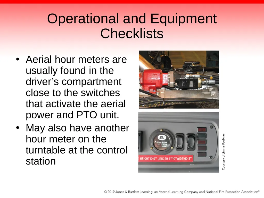
slide11. Operational and Equipment Checklists Aerial hour meters are usually found in the driver’s compartment close to the switches that activate the aerial power and PTO unit.
May also have another hour meter on the turntable at the control station Courtesy of Jimmy Faulkner.<br>
slide12. Operational and Equipment Checklists Aerial checklist will identify the specific items that need to be checked.
Great deal of controversy is associated with how much should be checked.
Departmental SOPs are written based on many items that come into play.
One department may test its unit only once per week, other departments will mandate a daily full check of the apparatus.<br>
slide13. Aerial Device Hydraulic Fluid Hydraulics can be found in numerous locations in the apparatus, including the following:
Under the aerial ladder
In the center of the truck under access door
On the tractor of the tiller-drawn aerial
Mounted integral to the cradle
Located above the pump module on quints<br>
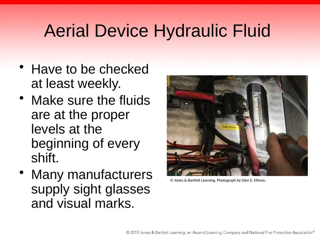
slide14. Aerial Device Hydraulic Fluid Have to be checked at least weekly.
Make sure the fluids are at the proper levels at the beginning of every shift.
Many manufacturers supply sight glasses and visual marks. © Jones & Bartlett Learning. Photograph by Glen E. Ellman.<br>
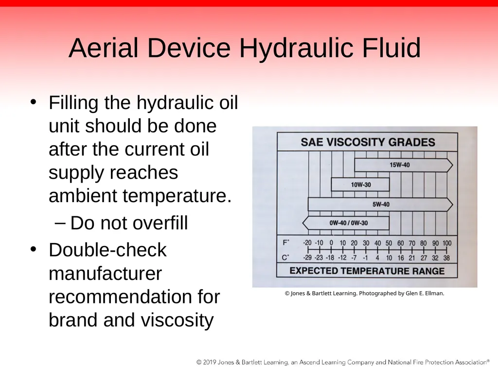
slide15. Aerial Device Hydraulic Fluid Filling the hydraulic oil unit should be done after the current oil supply reaches ambient temperature.
Do not overfill
Double-check manufacturer recommendation for brand and viscosity © Jones & Bartlett Learning. Photographed by Glen E. Ellman.<br>
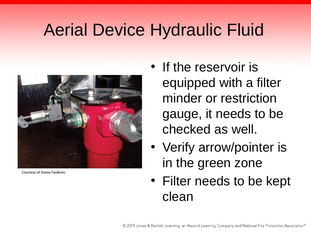
slide16. Aerial Device Hydraulic Fluid If the reservoir is equipped with a filter minder or restriction gauge, it needs to be checked as well.
Verify arrow/pointer is in the green zone
Filter needs to be kept clean Courtesy of Jimmy Faulkner.<br>
slide17. Stabilizer Systems Examine each stabilizer.
Assess whether the footplates attached to the aerial are fully retracted.
Shake the plate to check that the attached hardware is tight.
Look on the plate for any evidence of hydraulic oil leaking from the cylinder.
Observe whether the plates have experienced any impact damage.<br>
slide18. Stabilizer Systems Be sure the outrigger beams or under-slung stabilizers are fully retracted on the unit.
Listen and feel the truck for issues
NFPA 1911 mandates out-of-service criteria and deficiencies list in chapters 6.10.1 and 6.10.2.
Common sense plays a big role
When in doubt, take it out of service<br>
slide19. Extension Retraction and Hoist Cables Aerial cables are best observed while operating the unit and positioning the aerial over the back of the truck or on the side.
Then lower the aerial below the 0° grade and get a better view of the cables and control wires.
Obvious fail items include:
Frayed cables
Dry cables<br>
slide20. Extension Retraction and Hoist Cables Obvious fail items (cont’d):
Sagging cables during extension and retraction
Loose clevis pins and bolts on the end of the cables
Flexible cable protector or Igus track is binding or not flowing smoothly
Excessive squealing while moving the cables
Uneven sheave wheels (pulleys) that are binding while the ladder is moving<br>
slide21. Extension Retraction and Hoist Cables Obvious fail items (cont’d):
The ladder jerking from side to side while extending
Abrasion wear on the winch drum for older ladders with winch-style hoist systems for ladder extension and retraction
Check roller and roller assemblies
Loose or missing slide blocks<br>
slide22. Extension Retraction and Hoist Cables Checks can be part of the operational check.
Checklist should have a space to document any abnormal action that is experienced.
Also check for loose rung covers as well as proper side and lower roller operations.
Check security of the mounted tools on the tip.
Check the condition of the mounting hardware.<br>
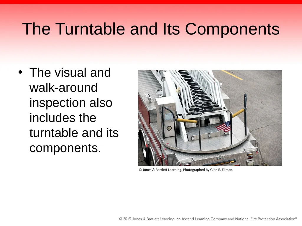
slide23. The Turntable and Its Components The visual and walk-around inspection also includes the turntable and its components. © Jones & Bartlett Learning. Photographed by Glen E. Ellman.<br>
slide24. Turntable Checklist Safety chains or protective guards are in place to keep fire fighters from falling off the turntable.
Turntable handrails are secure.
Evidence of impact on any component should be reported immediately for evaluation.
The turntable control box is secured and control door covers, safety devices, and lighting are functional.<br>
slide25. Turntable Checklist The dead man’s switch is functional.
There is no evidence of hydraulic leaks from any area on the turntable.
Indicator lights for the cradle alignment and rung alignment are functional.
If the PTO is engaged and there are no outriggers deployed or set, nothing should move when the operator attempts to raise the aerial by depressing the dead man’s switch.<br>
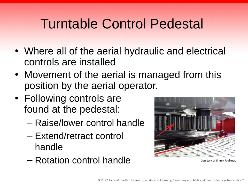
slide26. Turntable Control Pedestal Where all of the aerial hydraulic and electrical controls are installed
Movement of the aerial is managed from this position by the aerial operator.
Following controls are found at the pedestal:
Raise/lower control handle
Extend/retract control handle
Rotation control handle Courtesy of Jimmy Faulkner.<br>
slide27. Turntable Control Pedestal Controls found at the pedestal (cont’d):
Dead man’s switch
Master power switch
Nozzle controls
Hydraulic pressure gauge
Rung alignment indicator light
Cradle alignment light
Fast idle switch<br>
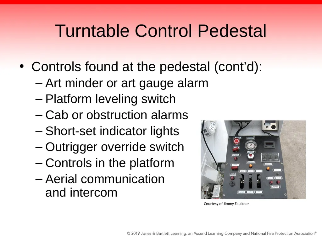
slide28. Turntable Control Pedestal Controls found at the pedestal (cont’d):
Art minder or art gauge alarm
Platform leveling switch
Cab or obstruction alarms
Short-set indicator lights
Outrigger override switch
Controls in the platform
Aerial communication and intercom Courtesy of Jimmy Faulkner.<br>
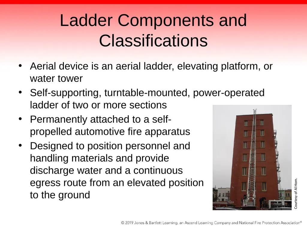
slide29. Ladder Components and Classifications Aerial device is an aerial ladder, elevating platform, or water tower
Self-supporting, turntable-mounted, power-operated ladder of two or more sections
Permanently attached to a self- propelled automotive fire apparatus
Designed to position personnel and handling materials and provide discharge water and a continuous egress route from an elevated position to the ground Courtesy of Al Hom.<br>
slide30. Ladder Sections Bottom section of the ladder is referred to as the base section.
Outermost ladder is called the fly section.
Other sections are called midsections.
If there are just three sections of ladder, the middle section is simply referred to as the midsection.<br>
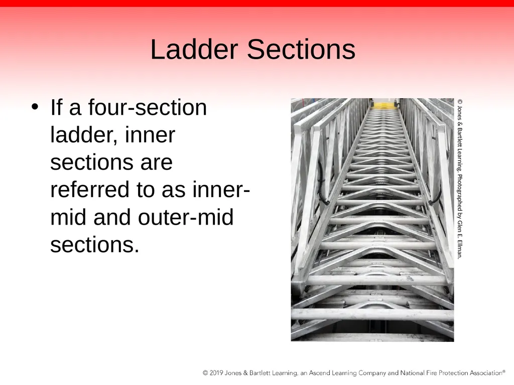
slide31. Ladder Sections If a four-section ladder, inner sections are referred to as inner-mid and outer-mid sections. © Jones & Bartlett Learning. Photographed by Glen E. Ellman.<br>
slide32. Lift Cylinders Largest and most powerful hydraulic system on the aerial apparatus
Used to raise and lower the aerial through the application of hydraulics
POC valves will hold the cylinders in the position requested.
Opens and allows fluid to pass only when it receives pressure from a valve being selected and operated<br>
slide33. Lift Cylinders If the driver/operator pulls back on the raise handle, the hydraulic pressure will flow into the cylinder block and open up the POC.
At that point, the fluid can flow into the cylinder on the bottom of the cylinder.
The lift is timed so that both cylinders raise and lift together and the ladder rises evenly.
When lowering the ladder, the same chain of events happens, only in reverse.<br>
slide34. Lift Cylinders In the past, many ladders relied on single-action cylinders.
Used hydraulic pressure to force the ladder up using the same ram and lift yokes or clevises; when the aerial was lowered, the weight of the ladder itself pushed the fluid out.
Advantage of double-acting cylinder is it allows the driver/operator to configure the unit to fly below the 0-degree grade and still have enough power to lift the aerial back up.<br>
slide35. Rotation Controls Have several hydraulic and moving parts that are required for rotating the aerial
Some aerial devices that have a long reach or heavy sections will utilize 2 rotation gears.
Reduces backlash
Provides a more positive control
Allows the manufacturer to use smaller swing drives in constructing the aerial apparatus<br>
slide36. Waterway and Associated Plumbing The minimum flow on an aerial device is 1000 gpm (4000 L/min).
To provide this flow, a ladder is equipped with its own waterway system.
System consists of two or more pipes that become progressively smaller as they telescope out of each other.
Can be one large pipe attached under the ladder or two smaller pipes, one down each side of the ladder<br>
slide37. Waterway and Associated Plumbing Waterways are sized to the flow that the fire department wants to project from the ladder.
Some aerials can flow 2000 gpm (8000 L/min) or better, depending on the water supply and pumping capacity.
Waterway system starts with a feeder or intake pipe that is found in the rear of the device—usually a 4-inch (100-mm) NST connection or larger.<br>
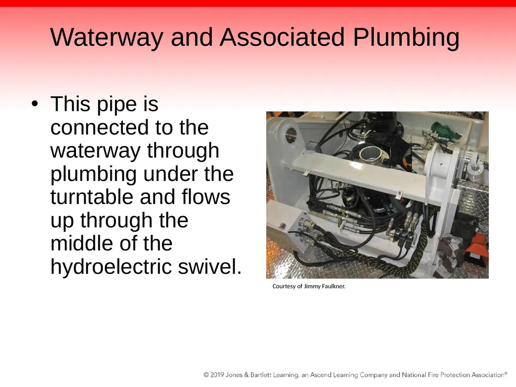
slide38. Waterway and Associated Plumbing This pipe is connected to the waterway through plumbing under the turntable and flows up through the middle of the hydroelectric swivel. Courtesy of Jimmy Faulkner.<br>
slide39. The Hydroelectric Swivel Allows the ladder to turn while the waterway stays connected
In the middle of the device is a water passage with victaulic connections on both the top and the bottom of the swivel.
Connects the lower plumbing to the aerial waterway pipe
Allows water to flow up from the bottom through the swivel and then through the waterway, coming out the monitor at the tip or platform<br>
slide40. The Hydroelectric Swivel Has passageways that allow hydraulic oil to be introduced at the bottom and come out the top
Also has wires from the electric controls and circuits that enter the swivel at the bottom and exit the top
Wiring uses a combination of collector rings that are installed inside the swivel and that allow the unit to rotate or swivel<br>
slide41. The Hydroelectric Swivel Unit has three cavities:
One for water through the middle
One for hydraulics in the core
One for electric power with the collector rings that makes contact with the brushes connected to the wiring harnesses<br>
slide42. Components of Ladder Sections: Rails and Rungs Base rails are the bottom part of the ladder that holds the rungs.
Rungs are the actual stepping surface that is used to climb the ladder.
The rungs have an outer diameter of 1¼ in
Should be capable of supporting 250 pounds.
Rung has to be able to support two fire fighters or a fire fighter and a victim.
Rungs must also provide nonslip surface.<br>
slide43. Components of Ladder Sections: K Braces Stiffening members of the lower rung and base rail assembly.
Attach at the base rails on both sides and at the rung in the middle
Looks like the letter K
Uprights and diagonals are vertical tubes that give the handrail its bracing and attaching point.<br>
slide44. Components of Ladder Sections: Handrails and Accessories Handrails are the rails that fire fighters hold onto while climbing each section of the ladder.
Need to be at least 1-inch tubing and must rise at least 12 inches from the base rail
Width between the handrails at the top must be at least 18 inches
Ladder-mounted accessories also found in fly section of aerial
Axes, pike poles, short ladders, and roof ladders<br>
slide45. Platform Controls Same as those found at the turntable control
All functions can be overridden by the turntable operator from the lower control station.
Stations can be mounted anywhere in the platform, and some manufacturers installed movable options.
Platform has breathing air hookups and places to store additional tools and handlines to deploy to upper floors when necessary.<br>
slide46. Platform Controls A valve is also provided that taps into the waterway pipe in the platform.
Protrudes through the protective cover installed under the platform and will spray up to 75 gpm (300 L/min) for cooling under the platform in case of impinging fire
Operated by personnel in the platform manually<br>
slide47. Platform Controls Two-man gates minimum for egress in and out of the platform are required.
Electric or manual controls for single or dual monitors are included in the controls.
Additional discharge valve with hose threads allow the platform to act like a standpipe connection when raised to an upper floor.<br>
slide48. Tiller Trucks Tractor-trailer aerial apparatus
More maneuverable than straight-chassis trucks because they bend in the middle and have the advantage of rear steering
Rear driver or tiller operator sits in a cab mounted on the back of the trailer behind the ladder tip.
Aerial ladder is attached to the trailer.<br>
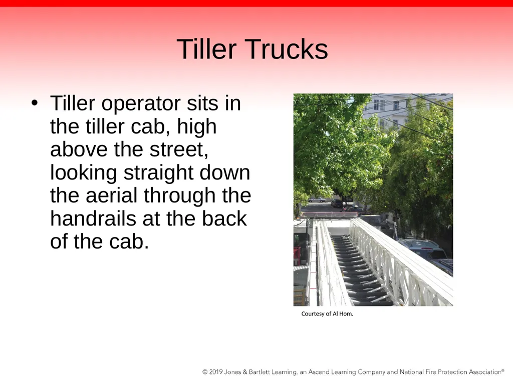
slide49. Tiller Trucks Tiller operator sits in the tiller cab, high above the street, looking straight down the aerial through the handrails at the back of the cab. Courtesy of Al Hom.<br>
slide50. Tiller Operator Has an unobstructed view, and his/her job is to steer the back of the trailer.
Turns the wheel in the opposite direction that the front driver/operator does.
Causes the whole unit to pivot instead of tracking like a trailer
Tiller operator can adjust the track of the trailer
Dead man’s switch prevents front driver from leaving without him/her<br>
slide51. Tiller Operator Dash-mounted gauge (rudder control indicator) informs the tiller operator of the position of the rear wheels—centered, left, or right.
The tiller operator plays a major role in capitalizing on the versatility of the tractor-drawn aerial.
Driving and maneuvering takes a lot of practice and coordination<br>
slide52. Aerial Device Operations Operational inspection of aerial devices should include operating the apparatus at least once every work period.
Department SOP will stipulate how often full inspections should occur.
Most important consideration in aerial operations is proper setup and good ground to work from.<br>
slide53. Placement and Foundation Ensure that the terrain and the ground are correct for placement of the apparatus.
Obstacles, dangerous terrain, and situations to be aware of when setting up an aerial:
Manhole covers
Newly constructed streets where the blacktop has not hardened and the base has not compressed under the asphalt level<br>
slide54. Placement and Foundation Considerations when setting up an aerial (cont’d):
Drains and sewer pipe openings
Overhead electric lines anywhere in the 360-degree rotation range of the aerial device
Sidewalks
Training and testing sites<br>
slide55. Placement and Foundation Always try to get the turntable in the best position for scrubbing the building and utilizing the maximum reach of the device.
Know the weight limits and horizontal reach of the device and confirm them through trial and practice during training.
Know the position of the cab control’s outrigger and aerial controls, so that these actions are committed to muscle memory.<br>
slide56. Placement and Foundation Practice the same way every time with your crew.
Understand that you must be able to set up the aerial apparatus alone if the situation dictates.<br>
slide57. Cab and Predeployment Procedures Before committing your unit, make sure that you are not in the collapse zone and that there is room for companies to pass you or lay lines whenever possible.
The aerial is most effective when deployed off the rear of the apparatus, because you can get maximum reach of the device with maximum stability.<br>
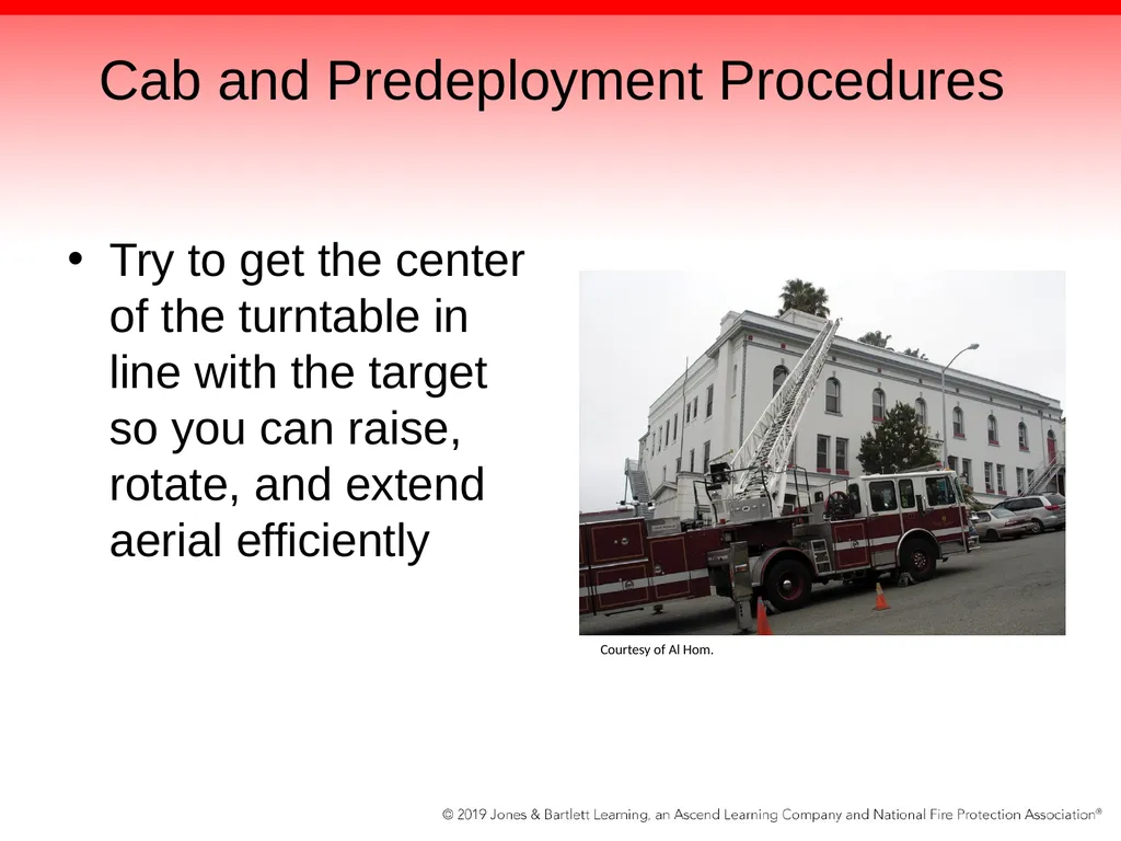
slide58. Cab and Predeployment Procedures Try to get the center of the turntable in line with the target so you can raise, rotate, and extend aerial efficiently Courtesy of Al Hom.<br>
slide59. Cab and Predeployment Procedures Before doing anything, set the spring brakes and put the truck transmission shifter into neutral.
Always put one hand on the brake knob and other on door latch when leaving cab
Know the location of the chocks and put them both under the front wheels.
In the worst-case scenario, you may have to set up the device alone.<br>
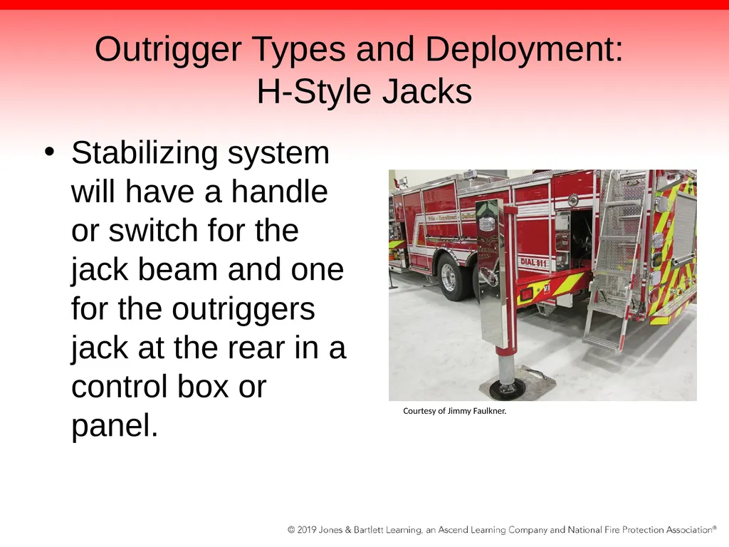
slide60. Outrigger Types and Deployment: H-Style Jacks Stabilizing system will have a handle or switch for the jack beam and one for the outriggers jack at the rear in a control box or panel. Courtesy of Jimmy Faulkner.<br>
slide61. Outrigger Types and Deployment: H-Style Jacks System has two major moving parts: the beam and the jack cylinder.
Beam is connected to a hydraulic ram located inside a steel-reinforced tube.
Beam tubes are placed horizontally in the torque box and are housed in a larger tube that allows the beam to slide in and out as the hydraulic cylinder extends and retracts the beam.<br>
slide62. Outrigger Types and Deployment: H-Style Jacks Jacks are connected to the end of the beam.
Lower the jack down or raise the jack up using a hydraulic cylinder inside the jack.
Systems are controlled from the valves actuated at the rear by the driver/operator.
Larger and heavier aerials may have up to four jacks<br>
slide63. Outrigger Types and Deployment: Modified H-Style Jacks Use a beam and a jack system.
Jack is mounted to the beam at a slight angle. Courtesy of Jimmy Faulkner.<br>
slide64. Outrigger Types and Deployment: Modified H-Style Jacks Deployment increases the footprint and jack spread and thereby provides for more stability.
A third control system adds a third motion to the truck setup.
Beams are still encased in a slightly larger tube, but the tube has a pivot.<br>
slide65. Outrigger Types and Deployment: Modified H-Style Jacks Additional hydraulic cylinder forces the beam to push down on a separate control as well.
The front system of the jacks in this setup is also angled, but the jacks just go down at an angle with no beam to move.
A modified H-style jack system gives more of a triangular base than a square base for the unit.<br>
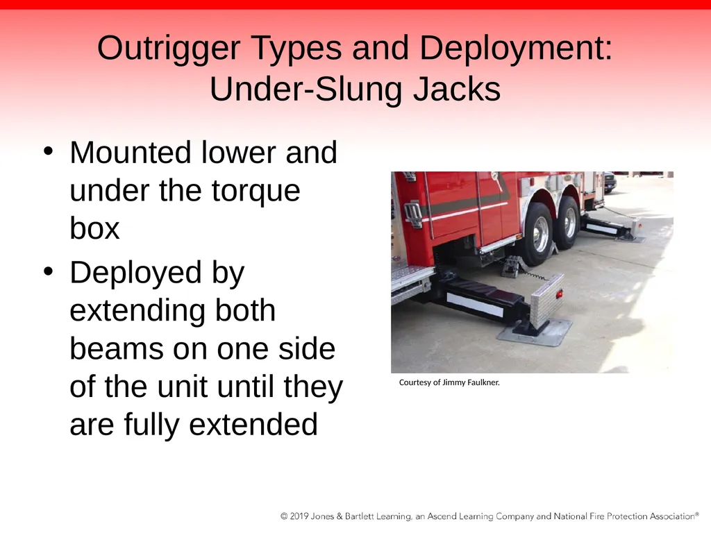
slide66. Outrigger Types and Deployment: Under-Slung Jacks Mounted lower and under the torque box
Deployed by extending both beams on one side of the unit until they are fully extended Courtesy of Jimmy Faulkner.<br>
slide67. Outrigger Types and Deployment: Under-Slung Jacks Driver/operator can pause and set jack ground plates under the unit and then return to the control.
Both beams will be pushed to the ground by a hydraulic cylinder activated by driver/operator.
Beams are also able to pivot and raise the truck using the downward force of the hydraulic cylinders.<br>
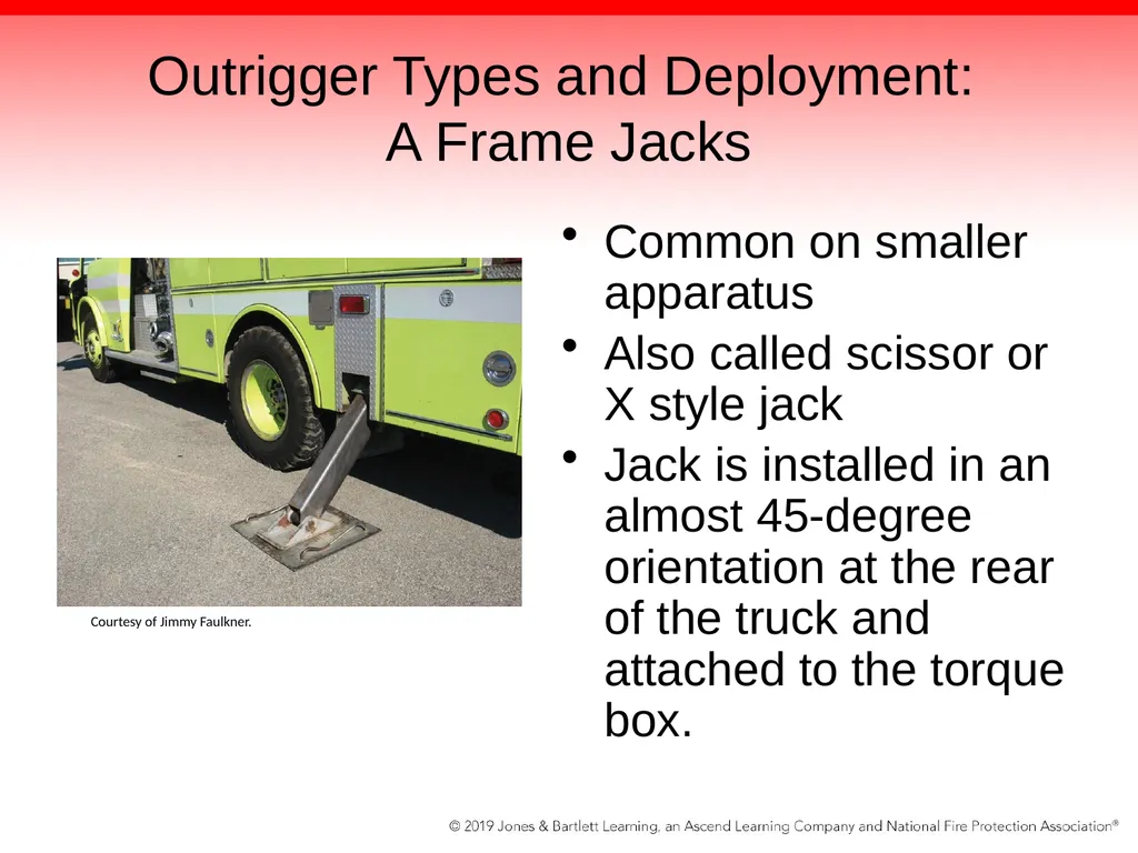
slide68. Outrigger Types and Deployment: A Frame Jacks Common on smaller apparatus
Also called scissor or X style jack
Jack is installed in an almost 45-degree orientation at the rear of the truck and attached to the torque box. Courtesy of Jimmy Faulkner.<br>
slide69. Outrigger Types and Deployment: A Frame Jacks Systems utilize inner and outer tubes, called a jack box.
To set the unit, the driver/operator holds the handle for either side jack until the truck is level.<br>
slide70. Fast Idle Control Each control station will have a fast idle switch.
Tells the diesel to idle up to 1000-1500 rpm to supply hydraulic volume and pressure
Should be utilized for outrigger deployment
Hydraulics will work at idle speed, but will operate more efficiently at fast idle settings.
To deactivate the fast idle control, toggle the momentary switch.<br>
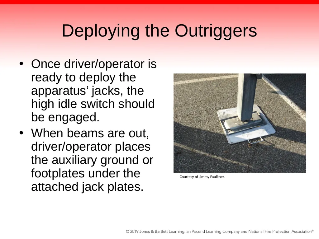
slide71. Deploying the Outriggers Once driver/operator is ready to deploy the apparatus’ jacks, the high idle switch should be engaged.
When beams are out, driver/operator places the auxiliary ground or footplates under the attached jack plates. Courtesy of Jimmy Faulkner.<br>
slide72. Deploying the Outriggers Once the ground plates are under the unit’s jacks, the driver/operator can begin to lower the jacks and raise the device.
Find the level gauge and get ready to set the truck to the green zone by operating the handles and lifting the truck one side at a time.<br>
slide73. Deploying the Outriggers Three colors on the level gauge:
Green zone: between 0 and 3.5 degrees.
Yellow zone: between 3.5 and 6.0 degrees.
Red zone: apparatus is exceeding safe limits.
Ideally, set up the apparatus so that the truck’s leveling ball shows zero degrees in the green zone.<br>
slide74. Outrigger Safety Devices On every function of the outrigger controls, there is a green light to indicate that the driver/operator has safely and successfully deployed that part of the device.
Sometimes, such as when there is a short street or a parked car in the way, it is not possible to extend a beam all the way out.
Once the truck is leveled, you can prepare to climb the access ladder to the turntable.<br>
slide75. Apparatus Classifications Aerial ladder apparatus
Elevating platforms
Telescoping aerial platforms
Aerial ladder platforms
Articulating aerial platforms
Water towers<br>
slide76. Operating the Aerial Device All aerial apparatus operate in basically the same manner.
Whether it is a two-piece telescoping squirt-type device or a four- or five-section ladder, it will generally have the same operating control characteristics.
To do anything with the device, it must be raised from the cradle or bed.<br>
slide77. Aerial Device Working Height Working height of the unit is measured from the ground to the highest ladder rung at full elevation.
Ladders are built with anywhere from 75 to 135 ft (23 to 41 m) of vertical height and can operate at up to 75 degrees of elevation.
Horizontal height is measured from the heel pin or centerline of the truck to the outermost reach of the ladder itself.<br>
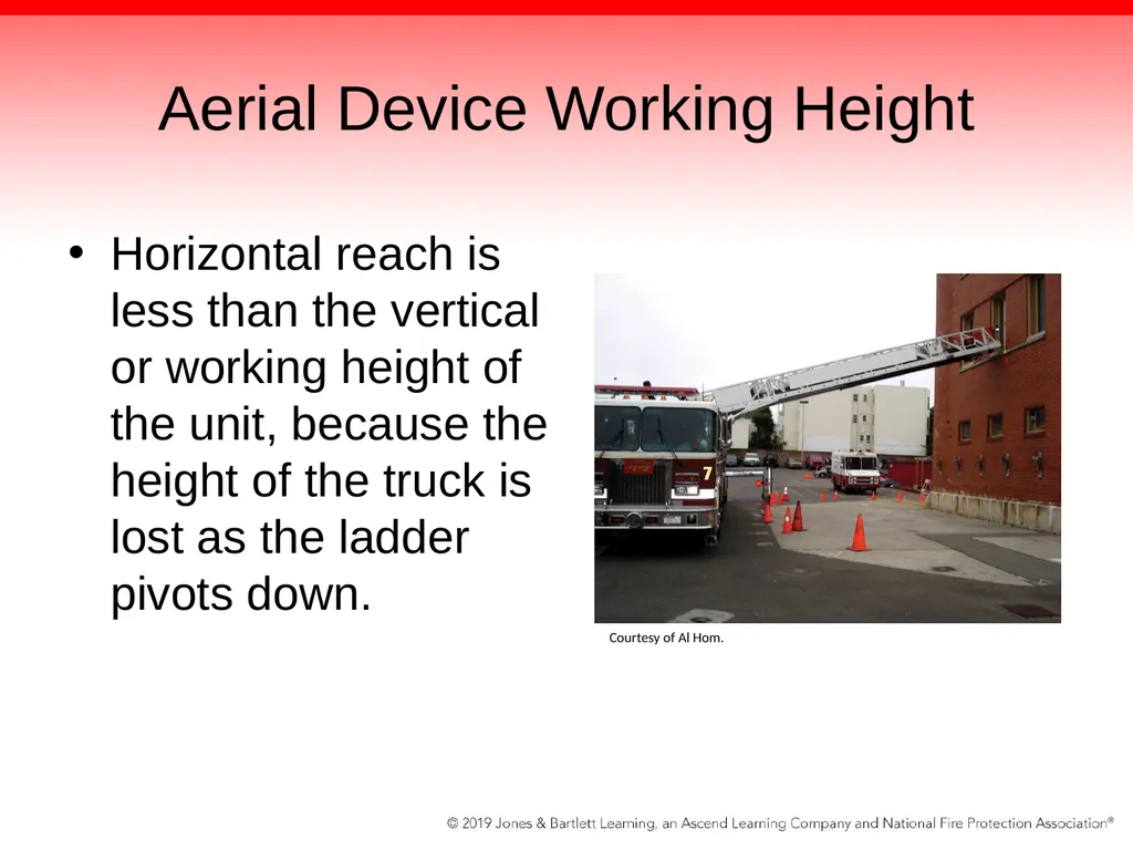
slide78. Aerial Device Working Height Horizontal reach is less than the vertical or working height of the unit, because the height of the truck is lost as the ladder pivots down. Courtesy of Al Hom.<br>
slide79. Angles of Operation Ladder trucks are capable of operating at different angles.
Newer aerial apparatus are capable of operating at full capacity while in angles ranging from –10 degrees to +75 degrees.<br>
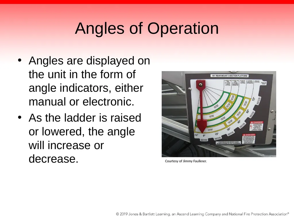
slide80. Angles of Operation Angles are displayed on the unit in the form of angle indicators, either manual or electronic.
As the ladder is raised or lowered, the angle will increase or decrease. Courtesy of Jimmy Faulkner.<br>
slide81. Angles of Operation When an aerial device is in the cradled or horizontal position, the angle is considered zero degrees.
Newer aerial devices with more powerful hydraulic systems are capable of lowering the ladder below zero degrees to a negative or below-horizontal angle.
Usually performed at 90 degrees off the side over the outriggers or directly over the back of the apparatus.<br>
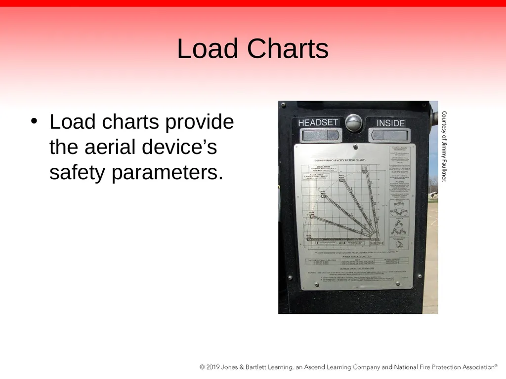
slide82. Load Charts Load charts provide the aerial device’s safety parameters. Courtesy of Jimmy Faulkner.<br>
slide83. Load Chart Information Tip load, or how many fire fighters and what weight can be carried on the outermost rung of the ladder
Number of fire fighters or distribution on each ladder section
Working height
Horizontal reach<br>
slide84. Load Chart Information Flow characteristics and gpm (L/min) capabilities
Flow capabilities and personnel limitations when working the ladder dry (with no water flowing) and when discharging water
Nozzle capabilities and ranges
Icing warnings<br>
slide85. Raising the Device Open the console cover and quickly check for any unsafe indicators, such as those signaling a short-set or outrigger not deployed.
Step on the dead man’s switch at the floor of the turntable.
“Klunk” indicates hydraulic pressure has been delivered to the control bank.
You will notice a rise in pressure on the hydraulic gauge.<br>
slide86. Raising the Device After stepping on dead man’s switch:
Make one last 360-degree scan.
Look at controls, look up for wires, and confirm no one in on the ladder.
To raise ladder gently and slowly, pull the raise handle back.
To lower the aerial, push the handle forward.
Once clear of obstructions, engage the fast idle switch and raise aerial to desired angle.<br>
slide87. Raising the Device New driver/operators need to gauge the relationship between the speed of the device and the amount of control action they input.
Every device is different and will react differently with fast idle settings.
Learn to watch the tip of the aerial when it moves.
The moving part is what you must watch.<br>
slide88. Rotation More accidents happen during the rotation phase than during any other operation of aerial devices.
Whenever possible, rotate to the side of the turntable control or pedestal.
Utilize the ladder tip lights whenever possible to visualize wires and to get an idea of where the aerial tip will set once you extend the ladder.
When rotating the device, look at the tip.<br>
slide89. Rotation The tip should move in the direction in which you move the handle.
Rotation speed is directly proportional to how much you push the handle forward.
Driver/operator must ensure that no one is attempting to climb up to or get on the turntable while it is rotating.
Driver/operator must power around and slowdown in smooth movements; otherwise ladder will backlash.<br>
slide90. Extension and Retraction Most aerial devices are 35 to 40 ft long when they are not extended and all sections are bottomed out in the fully retracted position.
To extend the ladder, the driver/operator pushes the control handle forward.
Double-acting or double-ram cylinders then move, causing the ladder to stretch out.
A series of cables in sheave wheels multiply the movements of the cylinders.<br>
slide91. Extension and Retraction Speed of extension depends on the slow or fast idle speed and the control handle input from the driver/operator.
Control allows the hydraulic fluid to enter slowly or rapidly, moving the cylinder and causing the ram to extend or retract.
Extension and retraction require that devices have either an indicator gauge or a set of numbers on the handrails.<br>
slide92. Extension and Retraction During extension, driver/operator has to be cognizant of a few things:
Tips of aerial ladders have different lights installed to illuminate the scene, but they do not always fit into windows.
The monitor on the fly section may stick out farther than the fly section itself and get in the way in a rescue situation.
Monitor is locked to the fly pipe by a pin or lever.<br>
slide93. Extension and Retraction Some aerial devices are capable of locking the monitor back at the outer midsection.
Allows the fly section to have a clear bottom without a waterway or monitor that might interfere with ladder placement
Also allows for crews’ quick deployment to roofs and over cornices for ventilation<br>
slide94. Extension and Retraction During the initial setup of an aerial device into rescue position, a fire fighter has to run down the ladder while it is cradled, make the monitor lock movement, and get off the ladder.
When extending or retracting the aerial, it is best to have a ground spotter assist the operator.<br>
slide95. Discharging Water and Waterway Safeties Some monitors contain a gate valve on the waterway that can block off the monitor flow, with a small valve mounted for standpipe use.
Make sure the monitor valve is open fully.
If your department uses electric fog or stream nozzles, get ready to raise the aerial device.
If your department uses straight-bore nozzles, you will need to select the proper size of smooth-bore tip based on the water supply.<br>
slide96. Discharging Water and Waterway Safeties Raise, rotate, and extend the aerial to the area where you will operate the stream.
Water supply should be connected to the aerial.
Driver/operator should be in contact with the engine and advise the operator to flow the pipe slowly and on command.
Do not allow the waterways to be charged unless the pipe is directed to a target.<br>
slide97. Discharging Water and Waterway Safeties Friction loss and nozzle pressure require that the engine apparatus driver/operator know the elevation as well as what gpm rate is needed.<br>
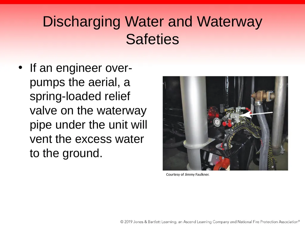
slide98. Discharging Water and Waterway Safeties If an engineer over-pumps the aerial, a spring-loaded relief valve on the waterway pipe under the unit will vent the excess water to the ground. Courtesy of Jimmy Faulkner.<br>
slide99. Discharging Water and Waterway Safeties On platforms flowing water, basket personnel must pay special attention to those streams.
Platform driver/operators should have a valve open all of the time.
Water should always be flowing during the fire operations.
Platforms may move into a variety of positions during the fire as a result of commands issued by the basket operator.<br>
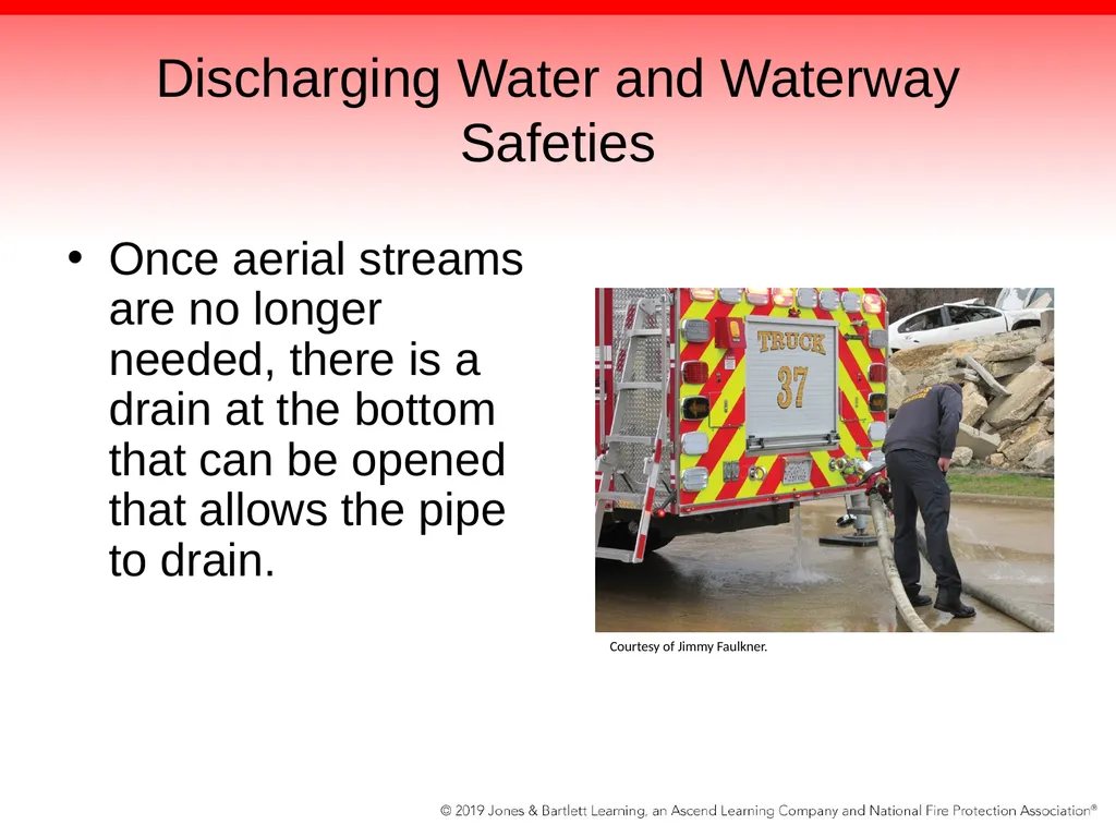
slide100. Discharging Water and Waterway Safeties Once aerial streams are no longer needed, there is a drain at the bottom that can be opened that allows the pipe to drain. Courtesy of Jimmy Faulkner.<br>
slide101. Discharging Water and Waterway Safeties Retraction of the ladder will not cause a problem if the tip valves stay open.
Problem usually occurs when the tip is shut down to turn the device into a standpipe connection.
In this scenario, a handline is connected to the 2½-inch connection and flows water for firefighting or mop-up purposes.
Handline is usually shut off at this valve for ladder retraction.<br>
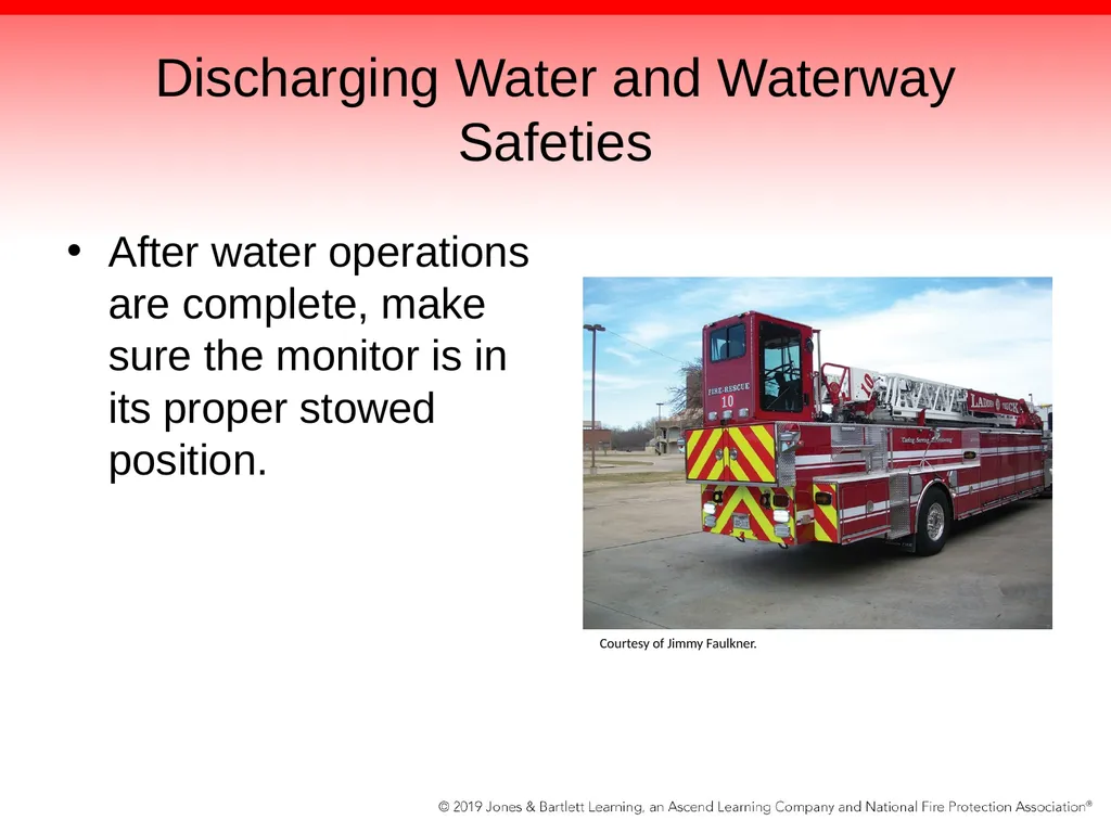
slide102. Discharging Water and Waterway Safeties After water operations are complete, make sure the monitor is in its proper stowed position. Courtesy of Jimmy Faulkner.<br>
slide103. Cradling Up and Going Home Retraction and stowing of the aerial device is the opposite of deployment.
Driver/operator engages the fast idle control, remembering the dead man’s switch.
After waterway has been drained and monitor has been stowed back into its nested position, the aerial device can be retracted.
When ladder sections get close to being fully retracted, driver/operator should ease off the retract control.<br>
slide104. Cradling Up and Going Home Try not to bang the ladders into their nested positions.
Watch the control cables, the igus track, and the ladder itself for abnormal movements, shaking, or misalignment, and report problems to a maintenance EVT.
Doing a 360-degree scan, rotate the ladder slowly until it aligns with the cradle.<br>
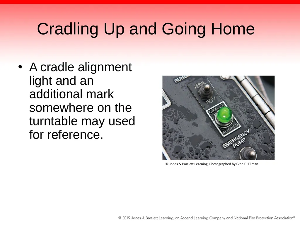
slide105. Cradling Up and Going Home A cradle alignment light and an additional mark somewhere on the turntable may used for reference. © Jones & Bartlett Learning. Photographed by Glen E. Ellman.<br>
slide106. Cradling Up and Going Home Next step is lowering the aerial.
Walk around the apparatus and confirm that the monitor is properly nested or stowed.
Confirm no one has left equipment under the ladder.
Lower the ladder by pushing the control handle forward, and control the speed of the hydraulics by varying input.
Once the ladder gets close to the cradle, double-check the alignment lights and marks and disengage the fast idle control.<br>
slide107. Cradling Up and Going Home Generally safer to lower into the cradle while the unit is operating on regular idle speed
Although the lights may indicate that the aerial is properly aligned, use your eyes to place the fly section of the ladder into the cradle.
Before leaving the turntable, power down the ladder into the cradle so the holding valves keep it locked down.<br>
slide108. Storing Outriggers Done in the opposite order of setup.
The jack’s hydraulic cylinders use the same power to retract up as they do when pushing down.
The last item deployed—either the jack cylinder or the beam plant cylinders—will be picked up first.
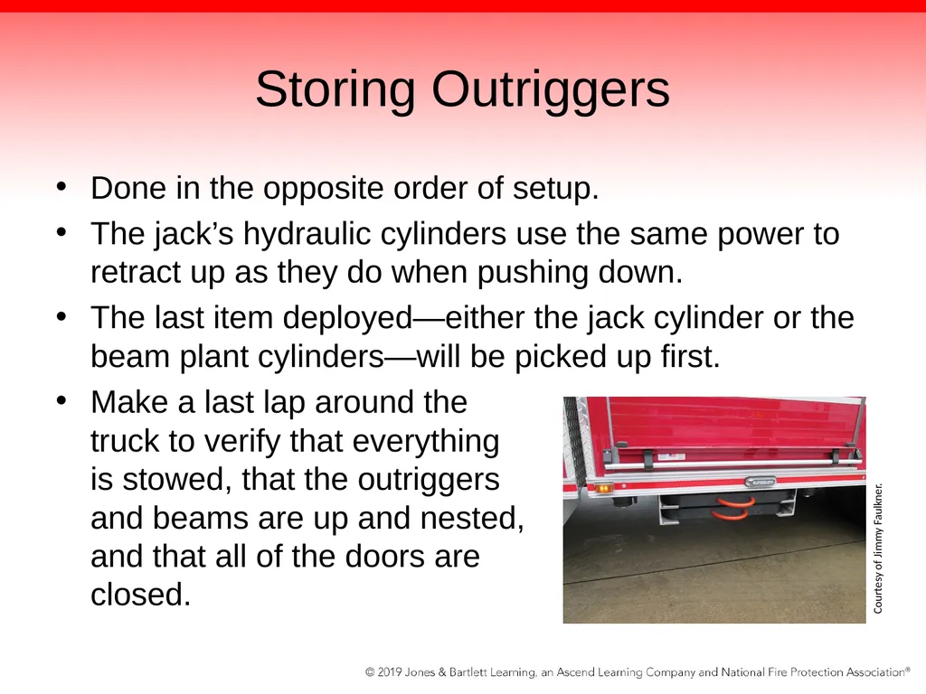
Make a last lap around the truck to verify that everything is stowed, that the outriggers and beams are up and nested, and that all of the doors are closed. Courtesy of Jimmy Faulkner.<br>
slide109. Apparatus Testing NFPA 1911 specifies the criteria for annual and NDT testing, and indicates which types of testing are required.
NDT seeks to test an aerial component without physically altering, disassembling, or damaging the unit.<br>
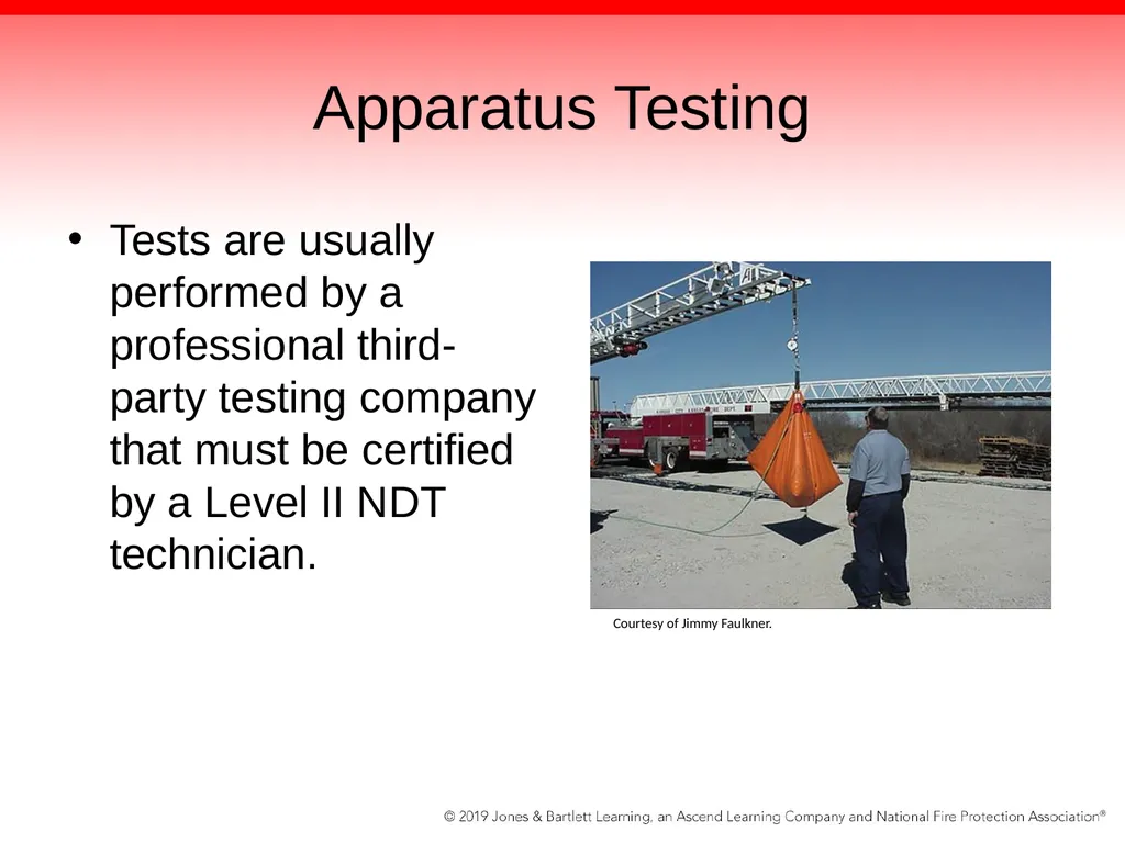
slide110. Apparatus Testing Tests are usually performed by a professional third-party testing company that must be certified by a Level II NDT technician. Courtesy of Jimmy Faulkner.<br>
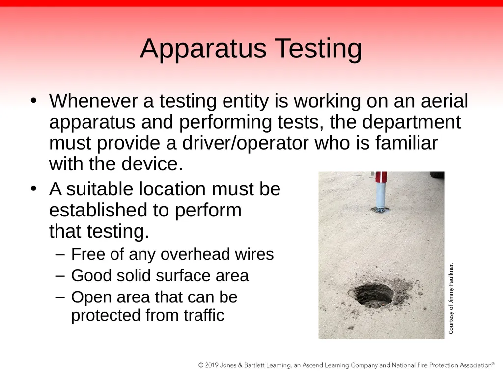
slide111. Apparatus Testing Whenever a testing entity is working on an aerial apparatus and performing tests, the department must provide a driver/operator who is familiar with the device.
A suitable location must be established to perform that testing.
Free of any overhead wires
Good solid surface area
Open area that can be protected from traffic Courtesy of Jimmy Faulkner.<br>
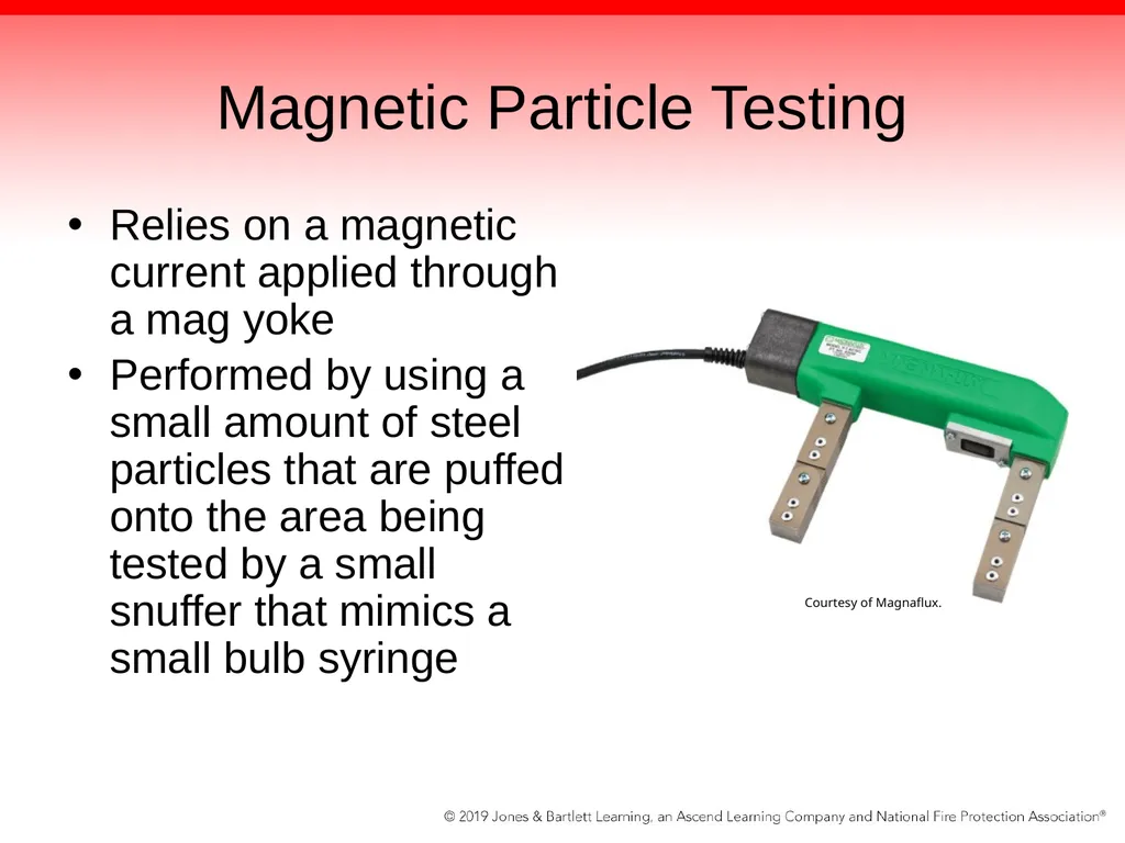
slide112. Magnetic Particle Testing Relies on a magnetic current applied through a mag yoke
Performed by using a small amount of steel particles that are puffed onto the area being tested by a small snuffer that mimics a small bulb syringe Courtesy of Magnaflux.<br>
slide113. Magnetic Particle Testing Metal particles will be pulled into any flaw or discontinuity by the magnetic current produced by the mag yoke when the Level II NDT technician presses the appropriate button.
Each crack is marked with a soap stone or grease pencil, and the flawed weld can be inspected and corrected by rewelding it.<br>
slide114. Acoustic Testing Utilizes sound waves to test a material for thickness
In aerial device testing, the sound waves travel through the ladder, and the return signal is translated to determine the density of the test site.
Technique is also used to test aluminum ladders by assessing their conductivity.<br>
slide115. Ultrasonic Testing Also uses sound waves but it relies on a scope that indicates if there are defects in the material via a display signature.
Used on bolts, ladder pins, sheave wheel pins, and ladder base rails
Areas that cannot be seen are the prime candidates.<br>
slide116. Dye Penetrant Testing Used to reveal surface defects only.
Colored dye is applied to the area of suspected deficiency then developer is applied.
Causes the dye to bleed to the surface and provides a visual indicator of the flaw © Jones & Bartlett Learning. Photographed by Glen E. Ellman.<br>
slide117. Additional Testing Turntable bolts and attaching hardware
Rotation bearing mounting bolts
Torque box mounting to the frame
Tractor mounts
Suspension
Rotation gear and bearings
Test criteria are intended to prevent a bolt failure<br>
slide118. Testing of Structural Components Structural components of aerial devices are also examined by a third-party testing company.
Leaks are located and corrected.
Items such as rollers, slide pads, and cables are adjusted due to wear or abuse.
Visual inspections and indicators are used to identify hydraulic internal leakage or holding valve failures.<br>
slide119. Structural Components Tested Rotation swivel and all lines and connections are checked for leaks, and smooth operations of the swivel should be the norm.
Elevation, extension, and rotation locks should be functional, with no external leakage.<br>
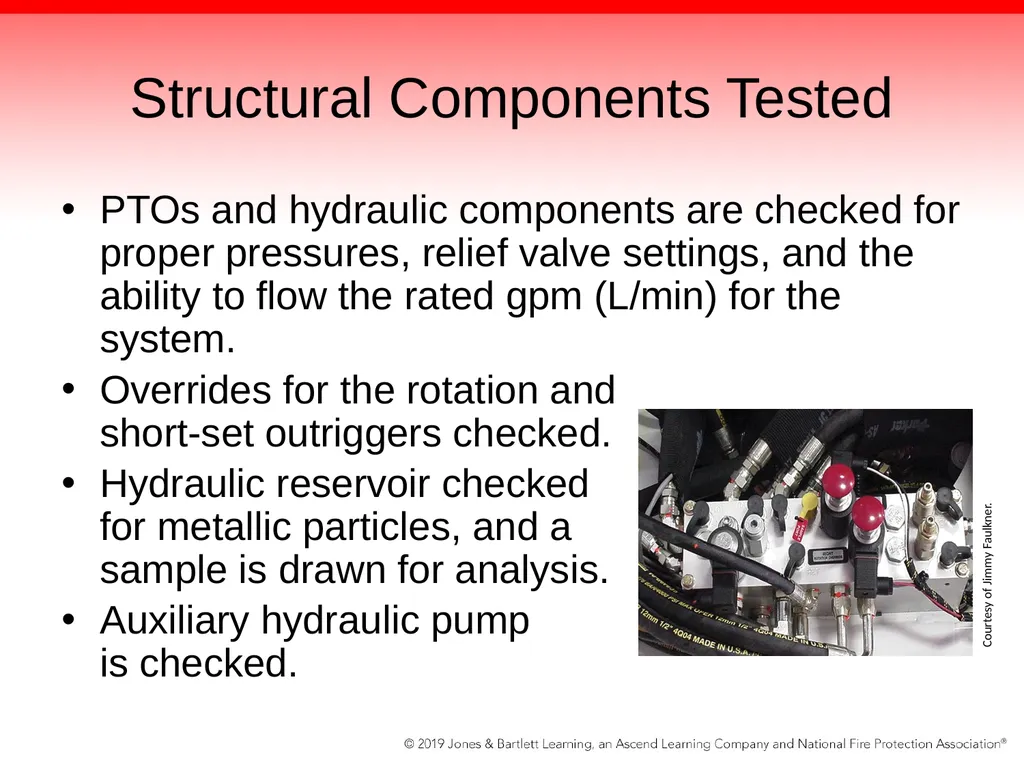
slide120. Structural Components Tested PTOs and hydraulic components are checked for proper pressures, relief valve settings, and the ability to flow the rated gpm (L/min) for the system.
Overrides for the rotation and short-set outriggers checked.
Hydraulic reservoir checked for metallic particles, and a sample is drawn for analysis.
Auxiliary hydraulic pump is checked. Courtesy of Jimmy Faulkner.<br>
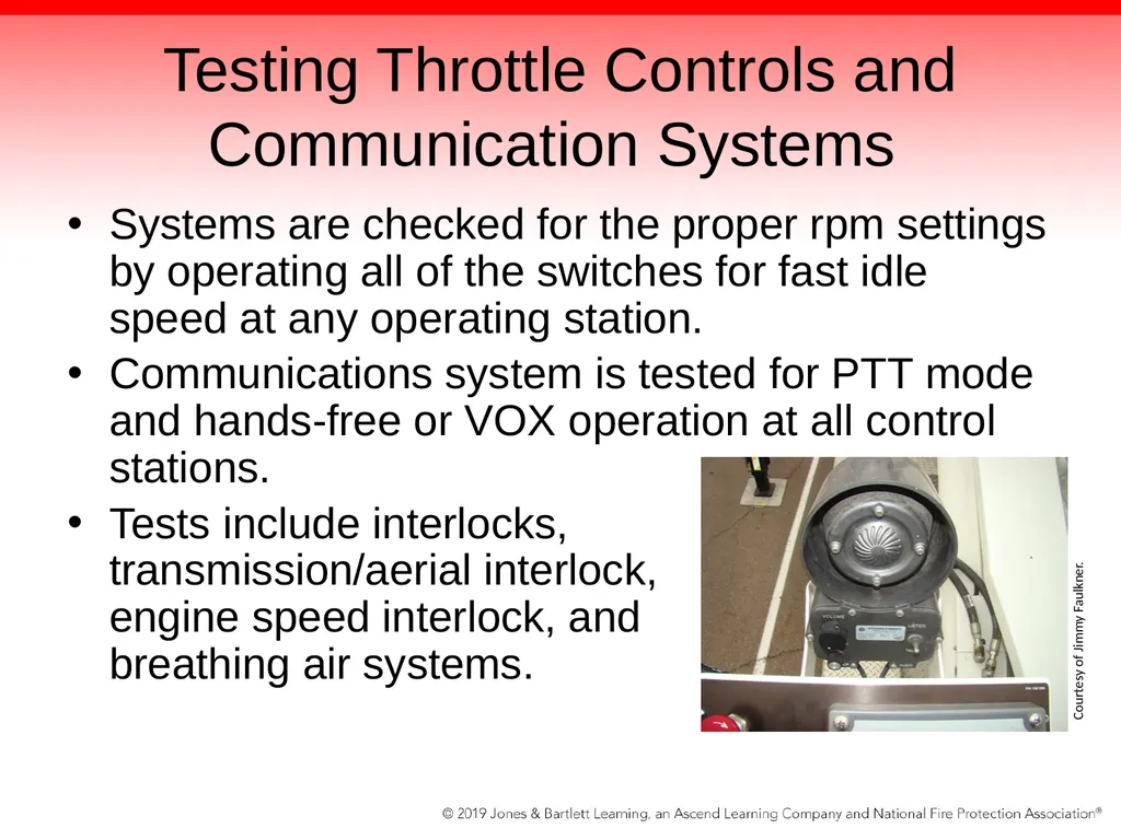
slide121. Testing Throttle Controls and Communication Systems Systems are checked for the proper rpm settings by operating all of the switches for fast idle speed at any operating station.
Communications system is tested for PTT mode and hands-free or VOX operation at all control stations.
Tests include interlocks, transmission/aerial interlock, engine speed interlock, and breathing air systems. Courtesy of Jimmy Faulkner.<br>
slide122. Stabilizer Inspections and Tests Stabilizers are checked for leaks and damaged parts.
Hoses are checked for rubbing, chaffing, and leaks at the fittings.
All stabilizer pads must be in place and all attaching hardware intact.
Inner and outer jack boxes should have no deformations, and pin holes should be rounded and not damaged.
Footplates or auxiliary pads should be provided for each outrigger.<br>
slide123. Stabilizer Inspections and Tests Mounting of the stabilizers to the body and the torque box are checked for cracks and deformities.
Any and all accessible bolts are checked for proper torque and replaced.
Switches that indicate short-set and jacks and beams deployed are checked for proper operation.
Cylinders are checked for internal leakage, and holding valves or POC valves are checked for drift.<br>
slide124. Stability and Load Test Ladder is tested for stability and load capacity.
Should be capable of sustaining a static load of 1½ times the rated capacity in every operational position
Water bag or container is suspended from a fully extended ladder.
Weight is gradually added and measured with a scale until the ladder’s rated capacity is being applied.<br>
slide125. Time Test Trial Allows the tester to see whether adequate hydraulic flow and control functions are operating on the device
Acquaints the driver/operator with the operating times needed to deploy the aerial device during actual firefighting operations
Requires the device to be on level ground, with all outriggers or stabilizers properly set<br>
slide126. Time Test Trial Tester instructs the designated driver/operator to raise the ladder to full elevation, rotate the device to 90 degrees, and fully extend the ladder or boom.
Timing starts when the ladder lifts from the cradle and stops when all three functions have been completed and the extension of the upper section stops.<br>
slide127. Water System Inspection and Test Aerial waterway is inspected for visual signs of damage, rust, corrosion, or other defects.
Water supply is attached and pressurized.
Waterway is filled with water and all air is removed from the piping.<br>
slide128. Water System Inspection and Test Once the ladder is full of water and reaches the maximum rated working pressure, the ladder is raised, extended, and rotated 360 degrees while charged.
Leaks are noted in waterway seals, plumbing and drains, all piping, and the hydroelectric swivel, and reported to EVT for repair<br>
slide129. Troubleshooting Aerial Problems During Tests and Checkouts All potential driver/operators of aerial and tiller truck devices should review the device-specific information provided by the OEM.
In-depth troubleshooting guide must be included with all aerial devices.
When problems with aerial apparatus develop that exceed the capabilities of the on-shift personnel, contact the appropriate EVT on the maintenance staff.<br>
slide130. Visual Cues to Alert the Driver/Operator to Problems Erratic or jerking ladder movements
Noises
Dragging sounds from the waterway
Any fluid leakage
Intermittent control functions on rotation
Cracks or rusty spots<br>
slide131. Visual Cues to Alert the Driver/Operator to Problems Ladder does not stop moving when control is released
Outrigger beams making noise on extension and retraction
Sagging extension and retraction cables
Tree limb damage
Loose ladder cradles<br>
slide132. Summary Do a 360-degree walk-around for aerial apparatus at the beginning of each shift.
Be familiar with all of the key points to check on each type of aerial they operate.
Aerial driver/operators should be familiar with the operating characteristics of the device and be able to recognize any difference in normal operations.<br>
slide133. Summary Be familiar with the aerial device parts and able to properly identify areas that need attention, either by the driver/operator or an EVT.
Be familiar with out-of-service criteria and able to properly access a situation regarding maintenance issues.
Perform operational checks in a safe area.<br>
slide134. Summary Be familiar with the pressure and load characteristics of their devices and should be able to read and understand load charts.
Know the minimum times allowed to deploy the aerial device and recognize which causes might potentially slow the device operational times down.<br>
slide135. Summary Know which types of fluids the device uses and where and when fluids need to be added.
Be able to lower the aerial device and stow it after any system failure, and also be aware of the function and location of system overrides and know when to use them.<br>
slide2. Knowledge Objectives Describe the routine tests, inspections, and servicing functions, for a given fire department’s aerial apparatus and tiller apparatus.
Describe the routine tests, inspections, and servicing functions, for a given fire department’s aerial apparatus and tiller apparatus, according to the manufacturer’s specifications and requirements, and the policies and procedures of the jurisdiction.<br>
slide3. Knowledge Objectives Describe the aerial device inspection requirements and process for cable systems (if applicable).
Describe the aerial device inspection requirements and process for aerial device hydraulic systems.
Describe the aerial device inspection requirements and process for slides and rollers.<br>
slide4. Knowledge Objectives Describe the aerial device inspection requirements and process for stabilizing systems.
Describe the aerial device inspection requirements and process for aerial device safety systems.
Describe the aerial device inspection requirements and process for breathing air systems.
Describe the aerial device inspection requirements and process for communication systems.<br>
slide5. Visual Inspection Begin any tour of duty or shift with same routine—an inspection of the apparatus.
Objective of this chapter is to teach personnel who operate aerial devices how and what to look for.<br>
slide6. The 360-Degree Turnaround First thing that should happen whenever any drill or when another shift turns over any type of apparatus
Provides first look at the condition of the vehicle
Can give you some good instant indicators of potential problems before you take custody of the rig
Provides you with an initial size-up<br>
slide7. The 360-Degree Turnaround Check that the apparatus is clean.
Check that all the tools are on the rig and stowed where they belong.
Check for any visible leaks or fluids under the unit or anywhere on the truck’s system.
Thump all of the tires and remember that you will check them later with a pressure gauge.
Check that all the compartments are shut.<br>
slide8. The 360-Degree Turnaround Check that all the outriggers are properly stowed and that all the chocks and ground plates are in their holders.
Check that all the ground ladders are safely secured in their racks and that the doors to the ladder compartment are secured.
Check that the truck is plugged into the shore line power to keep the batteries and the accessories on the rig charged.<br>
slide9. The 360-Degree Turnaround Look up, and see if anything seems out of place on the aerial itself.
Check for any broken lenses or glass from the previous night’s run.
Check with the last shift’s driver/operator regarding:
Which runs the crew had
If the members used the aerial apparatus on the last shift
Which actions they performed and how long the apparatus was used<br>
slide10. Operational and Equipment Checklists Should be designated procedures and qualified personnel responsible for operations, testing, and maintenance of aerial devices
At a minimum, follow OEM recommendations.
Most OEMs have set time-based standards for specific items to be checked on the devices; usually linked to the 10-, 50-, 100-, 200-, and 400-hour times located on the aerial hour meter.<br>
slide11. Operational and Equipment Checklists Aerial hour meters are usually found in the driver’s compartment close to the switches that activate the aerial power and PTO unit.
May also have another hour meter on the turntable at the control station Courtesy of Jimmy Faulkner.<br>
slide12. Operational and Equipment Checklists Aerial checklist will identify the specific items that need to be checked.
Great deal of controversy is associated with how much should be checked.
Departmental SOPs are written based on many items that come into play.
One department may test its unit only once per week, other departments will mandate a daily full check of the apparatus.<br>
slide13. Aerial Device Hydraulic Fluid Hydraulics can be found in numerous locations in the apparatus, including the following:
Under the aerial ladder
In the center of the truck under access door
On the tractor of the tiller-drawn aerial
Mounted integral to the cradle
Located above the pump module on quints<br>
slide14. Aerial Device Hydraulic Fluid Have to be checked at least weekly.
Make sure the fluids are at the proper levels at the beginning of every shift.
Many manufacturers supply sight glasses and visual marks. © Jones & Bartlett Learning. Photograph by Glen E. Ellman.<br>
slide15. Aerial Device Hydraulic Fluid Filling the hydraulic oil unit should be done after the current oil supply reaches ambient temperature.
Do not overfill
Double-check manufacturer recommendation for brand and viscosity © Jones & Bartlett Learning. Photographed by Glen E. Ellman.<br>
slide16. Aerial Device Hydraulic Fluid If the reservoir is equipped with a filter minder or restriction gauge, it needs to be checked as well.
Verify arrow/pointer is in the green zone
Filter needs to be kept clean Courtesy of Jimmy Faulkner.<br>
slide17. Stabilizer Systems Examine each stabilizer.
Assess whether the footplates attached to the aerial are fully retracted.
Shake the plate to check that the attached hardware is tight.
Look on the plate for any evidence of hydraulic oil leaking from the cylinder.
Observe whether the plates have experienced any impact damage.<br>
slide18. Stabilizer Systems Be sure the outrigger beams or under-slung stabilizers are fully retracted on the unit.
Listen and feel the truck for issues
NFPA 1911 mandates out-of-service criteria and deficiencies list in chapters 6.10.1 and 6.10.2.
Common sense plays a big role
When in doubt, take it out of service<br>
slide19. Extension Retraction and Hoist Cables Aerial cables are best observed while operating the unit and positioning the aerial over the back of the truck or on the side.
Then lower the aerial below the 0° grade and get a better view of the cables and control wires.
Obvious fail items include:
Frayed cables
Dry cables<br>
slide20. Extension Retraction and Hoist Cables Obvious fail items (cont’d):
Sagging cables during extension and retraction
Loose clevis pins and bolts on the end of the cables
Flexible cable protector or Igus track is binding or not flowing smoothly
Excessive squealing while moving the cables
Uneven sheave wheels (pulleys) that are binding while the ladder is moving<br>
slide21. Extension Retraction and Hoist Cables Obvious fail items (cont’d):
The ladder jerking from side to side while extending
Abrasion wear on the winch drum for older ladders with winch-style hoist systems for ladder extension and retraction
Check roller and roller assemblies
Loose or missing slide blocks<br>
slide22. Extension Retraction and Hoist Cables Checks can be part of the operational check.
Checklist should have a space to document any abnormal action that is experienced.
Also check for loose rung covers as well as proper side and lower roller operations.
Check security of the mounted tools on the tip.
Check the condition of the mounting hardware.<br>
slide23. The Turntable and Its Components The visual and walk-around inspection also includes the turntable and its components. © Jones & Bartlett Learning. Photographed by Glen E. Ellman.<br>
slide24. Turntable Checklist Safety chains or protective guards are in place to keep fire fighters from falling off the turntable.
Turntable handrails are secure.
Evidence of impact on any component should be reported immediately for evaluation.
The turntable control box is secured and control door covers, safety devices, and lighting are functional.<br>
slide25. Turntable Checklist The dead man’s switch is functional.
There is no evidence of hydraulic leaks from any area on the turntable.
Indicator lights for the cradle alignment and rung alignment are functional.
If the PTO is engaged and there are no outriggers deployed or set, nothing should move when the operator attempts to raise the aerial by depressing the dead man’s switch.<br>
slide26. Turntable Control Pedestal Where all of the aerial hydraulic and electrical controls are installed
Movement of the aerial is managed from this position by the aerial operator.
Following controls are found at the pedestal:
Raise/lower control handle
Extend/retract control handle
Rotation control handle Courtesy of Jimmy Faulkner.<br>
slide27. Turntable Control Pedestal Controls found at the pedestal (cont’d):
Dead man’s switch
Master power switch
Nozzle controls
Hydraulic pressure gauge
Rung alignment indicator light
Cradle alignment light
Fast idle switch<br>
slide28. Turntable Control Pedestal Controls found at the pedestal (cont’d):
Art minder or art gauge alarm
Platform leveling switch
Cab or obstruction alarms
Short-set indicator lights
Outrigger override switch
Controls in the platform
Aerial communication and intercom Courtesy of Jimmy Faulkner.<br>
slide29. Ladder Components and Classifications Aerial device is an aerial ladder, elevating platform, or water tower
Self-supporting, turntable-mounted, power-operated ladder of two or more sections
Permanently attached to a self- propelled automotive fire apparatus
Designed to position personnel and handling materials and provide discharge water and a continuous egress route from an elevated position to the ground Courtesy of Al Hom.<br>
slide30. Ladder Sections Bottom section of the ladder is referred to as the base section.
Outermost ladder is called the fly section.
Other sections are called midsections.
If there are just three sections of ladder, the middle section is simply referred to as the midsection.<br>
slide31. Ladder Sections If a four-section ladder, inner sections are referred to as inner-mid and outer-mid sections. © Jones & Bartlett Learning. Photographed by Glen E. Ellman.<br>
slide32. Lift Cylinders Largest and most powerful hydraulic system on the aerial apparatus
Used to raise and lower the aerial through the application of hydraulics
POC valves will hold the cylinders in the position requested.
Opens and allows fluid to pass only when it receives pressure from a valve being selected and operated<br>
slide33. Lift Cylinders If the driver/operator pulls back on the raise handle, the hydraulic pressure will flow into the cylinder block and open up the POC.
At that point, the fluid can flow into the cylinder on the bottom of the cylinder.
The lift is timed so that both cylinders raise and lift together and the ladder rises evenly.
When lowering the ladder, the same chain of events happens, only in reverse.<br>
slide34. Lift Cylinders In the past, many ladders relied on single-action cylinders.
Used hydraulic pressure to force the ladder up using the same ram and lift yokes or clevises; when the aerial was lowered, the weight of the ladder itself pushed the fluid out.
Advantage of double-acting cylinder is it allows the driver/operator to configure the unit to fly below the 0-degree grade and still have enough power to lift the aerial back up.<br>
slide35. Rotation Controls Have several hydraulic and moving parts that are required for rotating the aerial
Some aerial devices that have a long reach or heavy sections will utilize 2 rotation gears.
Reduces backlash
Provides a more positive control
Allows the manufacturer to use smaller swing drives in constructing the aerial apparatus<br>
slide36. Waterway and Associated Plumbing The minimum flow on an aerial device is 1000 gpm (4000 L/min).
To provide this flow, a ladder is equipped with its own waterway system.
System consists of two or more pipes that become progressively smaller as they telescope out of each other.
Can be one large pipe attached under the ladder or two smaller pipes, one down each side of the ladder<br>
slide37. Waterway and Associated Plumbing Waterways are sized to the flow that the fire department wants to project from the ladder.
Some aerials can flow 2000 gpm (8000 L/min) or better, depending on the water supply and pumping capacity.
Waterway system starts with a feeder or intake pipe that is found in the rear of the device—usually a 4-inch (100-mm) NST connection or larger.<br>
slide38. Waterway and Associated Plumbing This pipe is connected to the waterway through plumbing under the turntable and flows up through the middle of the hydroelectric swivel. Courtesy of Jimmy Faulkner.<br>
slide39. The Hydroelectric Swivel Allows the ladder to turn while the waterway stays connected
In the middle of the device is a water passage with victaulic connections on both the top and the bottom of the swivel.
Connects the lower plumbing to the aerial waterway pipe
Allows water to flow up from the bottom through the swivel and then through the waterway, coming out the monitor at the tip or platform<br>
slide40. The Hydroelectric Swivel Has passageways that allow hydraulic oil to be introduced at the bottom and come out the top
Also has wires from the electric controls and circuits that enter the swivel at the bottom and exit the top
Wiring uses a combination of collector rings that are installed inside the swivel and that allow the unit to rotate or swivel<br>
slide41. The Hydroelectric Swivel Unit has three cavities:
One for water through the middle
One for hydraulics in the core
One for electric power with the collector rings that makes contact with the brushes connected to the wiring harnesses<br>
slide42. Components of Ladder Sections: Rails and Rungs Base rails are the bottom part of the ladder that holds the rungs.
Rungs are the actual stepping surface that is used to climb the ladder.
The rungs have an outer diameter of 1¼ in
Should be capable of supporting 250 pounds.
Rung has to be able to support two fire fighters or a fire fighter and a victim.
Rungs must also provide nonslip surface.<br>
slide43. Components of Ladder Sections: K Braces Stiffening members of the lower rung and base rail assembly.
Attach at the base rails on both sides and at the rung in the middle
Looks like the letter K
Uprights and diagonals are vertical tubes that give the handrail its bracing and attaching point.<br>
slide44. Components of Ladder Sections: Handrails and Accessories Handrails are the rails that fire fighters hold onto while climbing each section of the ladder.
Need to be at least 1-inch tubing and must rise at least 12 inches from the base rail
Width between the handrails at the top must be at least 18 inches
Ladder-mounted accessories also found in fly section of aerial
Axes, pike poles, short ladders, and roof ladders<br>
slide45. Platform Controls Same as those found at the turntable control
All functions can be overridden by the turntable operator from the lower control station.
Stations can be mounted anywhere in the platform, and some manufacturers installed movable options.
Platform has breathing air hookups and places to store additional tools and handlines to deploy to upper floors when necessary.<br>
slide46. Platform Controls A valve is also provided that taps into the waterway pipe in the platform.
Protrudes through the protective cover installed under the platform and will spray up to 75 gpm (300 L/min) for cooling under the platform in case of impinging fire
Operated by personnel in the platform manually<br>
slide47. Platform Controls Two-man gates minimum for egress in and out of the platform are required.
Electric or manual controls for single or dual monitors are included in the controls.
Additional discharge valve with hose threads allow the platform to act like a standpipe connection when raised to an upper floor.<br>
slide48. Tiller Trucks Tractor-trailer aerial apparatus
More maneuverable than straight-chassis trucks because they bend in the middle and have the advantage of rear steering
Rear driver or tiller operator sits in a cab mounted on the back of the trailer behind the ladder tip.
Aerial ladder is attached to the trailer.<br>
slide49. Tiller Trucks Tiller operator sits in the tiller cab, high above the street, looking straight down the aerial through the handrails at the back of the cab. Courtesy of Al Hom.<br>
slide50. Tiller Operator Has an unobstructed view, and his/her job is to steer the back of the trailer.
Turns the wheel in the opposite direction that the front driver/operator does.
Causes the whole unit to pivot instead of tracking like a trailer
Tiller operator can adjust the track of the trailer
Dead man’s switch prevents front driver from leaving without him/her<br>
slide51. Tiller Operator Dash-mounted gauge (rudder control indicator) informs the tiller operator of the position of the rear wheels—centered, left, or right.
The tiller operator plays a major role in capitalizing on the versatility of the tractor-drawn aerial.
Driving and maneuvering takes a lot of practice and coordination<br>
slide52. Aerial Device Operations Operational inspection of aerial devices should include operating the apparatus at least once every work period.
Department SOP will stipulate how often full inspections should occur.
Most important consideration in aerial operations is proper setup and good ground to work from.<br>
slide53. Placement and Foundation Ensure that the terrain and the ground are correct for placement of the apparatus.
Obstacles, dangerous terrain, and situations to be aware of when setting up an aerial:
Manhole covers
Newly constructed streets where the blacktop has not hardened and the base has not compressed under the asphalt level<br>
slide54. Placement and Foundation Considerations when setting up an aerial (cont’d):
Drains and sewer pipe openings
Overhead electric lines anywhere in the 360-degree rotation range of the aerial device
Sidewalks
Training and testing sites<br>
slide55. Placement and Foundation Always try to get the turntable in the best position for scrubbing the building and utilizing the maximum reach of the device.
Know the weight limits and horizontal reach of the device and confirm them through trial and practice during training.
Know the position of the cab control’s outrigger and aerial controls, so that these actions are committed to muscle memory.<br>
slide56. Placement and Foundation Practice the same way every time with your crew.
Understand that you must be able to set up the aerial apparatus alone if the situation dictates.<br>
slide57. Cab and Predeployment Procedures Before committing your unit, make sure that you are not in the collapse zone and that there is room for companies to pass you or lay lines whenever possible.
The aerial is most effective when deployed off the rear of the apparatus, because you can get maximum reach of the device with maximum stability.<br>
slide58. Cab and Predeployment Procedures Try to get the center of the turntable in line with the target so you can raise, rotate, and extend aerial efficiently Courtesy of Al Hom.<br>
slide59. Cab and Predeployment Procedures Before doing anything, set the spring brakes and put the truck transmission shifter into neutral.
Always put one hand on the brake knob and other on door latch when leaving cab
Know the location of the chocks and put them both under the front wheels.
In the worst-case scenario, you may have to set up the device alone.<br>
slide60. Outrigger Types and Deployment: H-Style Jacks Stabilizing system will have a handle or switch for the jack beam and one for the outriggers jack at the rear in a control box or panel. Courtesy of Jimmy Faulkner.<br>
slide61. Outrigger Types and Deployment: H-Style Jacks System has two major moving parts: the beam and the jack cylinder.
Beam is connected to a hydraulic ram located inside a steel-reinforced tube.
Beam tubes are placed horizontally in the torque box and are housed in a larger tube that allows the beam to slide in and out as the hydraulic cylinder extends and retracts the beam.<br>
slide62. Outrigger Types and Deployment: H-Style Jacks Jacks are connected to the end of the beam.
Lower the jack down or raise the jack up using a hydraulic cylinder inside the jack.
Systems are controlled from the valves actuated at the rear by the driver/operator.
Larger and heavier aerials may have up to four jacks<br>
slide63. Outrigger Types and Deployment: Modified H-Style Jacks Use a beam and a jack system.
Jack is mounted to the beam at a slight angle. Courtesy of Jimmy Faulkner.<br>
slide64. Outrigger Types and Deployment: Modified H-Style Jacks Deployment increases the footprint and jack spread and thereby provides for more stability.
A third control system adds a third motion to the truck setup.
Beams are still encased in a slightly larger tube, but the tube has a pivot.<br>
slide65. Outrigger Types and Deployment: Modified H-Style Jacks Additional hydraulic cylinder forces the beam to push down on a separate control as well.
The front system of the jacks in this setup is also angled, but the jacks just go down at an angle with no beam to move.
A modified H-style jack system gives more of a triangular base than a square base for the unit.<br>
slide66. Outrigger Types and Deployment: Under-Slung Jacks Mounted lower and under the torque box
Deployed by extending both beams on one side of the unit until they are fully extended Courtesy of Jimmy Faulkner.<br>
slide67. Outrigger Types and Deployment: Under-Slung Jacks Driver/operator can pause and set jack ground plates under the unit and then return to the control.
Both beams will be pushed to the ground by a hydraulic cylinder activated by driver/operator.
Beams are also able to pivot and raise the truck using the downward force of the hydraulic cylinders.<br>
slide68. Outrigger Types and Deployment: A Frame Jacks Common on smaller apparatus
Also called scissor or X style jack
Jack is installed in an almost 45-degree orientation at the rear of the truck and attached to the torque box. Courtesy of Jimmy Faulkner.<br>
slide69. Outrigger Types and Deployment: A Frame Jacks Systems utilize inner and outer tubes, called a jack box.
To set the unit, the driver/operator holds the handle for either side jack until the truck is level.<br>
slide70. Fast Idle Control Each control station will have a fast idle switch.
Tells the diesel to idle up to 1000-1500 rpm to supply hydraulic volume and pressure
Should be utilized for outrigger deployment
Hydraulics will work at idle speed, but will operate more efficiently at fast idle settings.
To deactivate the fast idle control, toggle the momentary switch.<br>
slide71. Deploying the Outriggers Once driver/operator is ready to deploy the apparatus’ jacks, the high idle switch should be engaged.
When beams are out, driver/operator places the auxiliary ground or footplates under the attached jack plates. Courtesy of Jimmy Faulkner.<br>
slide72. Deploying the Outriggers Once the ground plates are under the unit’s jacks, the driver/operator can begin to lower the jacks and raise the device.
Find the level gauge and get ready to set the truck to the green zone by operating the handles and lifting the truck one side at a time.<br>
slide73. Deploying the Outriggers Three colors on the level gauge:
Green zone: between 0 and 3.5 degrees.
Yellow zone: between 3.5 and 6.0 degrees.
Red zone: apparatus is exceeding safe limits.
Ideally, set up the apparatus so that the truck’s leveling ball shows zero degrees in the green zone.<br>
slide74. Outrigger Safety Devices On every function of the outrigger controls, there is a green light to indicate that the driver/operator has safely and successfully deployed that part of the device.
Sometimes, such as when there is a short street or a parked car in the way, it is not possible to extend a beam all the way out.
Once the truck is leveled, you can prepare to climb the access ladder to the turntable.<br>
slide75. Apparatus Classifications Aerial ladder apparatus
Elevating platforms
Telescoping aerial platforms
Aerial ladder platforms
Articulating aerial platforms
Water towers<br>
slide76. Operating the Aerial Device All aerial apparatus operate in basically the same manner.
Whether it is a two-piece telescoping squirt-type device or a four- or five-section ladder, it will generally have the same operating control characteristics.
To do anything with the device, it must be raised from the cradle or bed.<br>
slide77. Aerial Device Working Height Working height of the unit is measured from the ground to the highest ladder rung at full elevation.
Ladders are built with anywhere from 75 to 135 ft (23 to 41 m) of vertical height and can operate at up to 75 degrees of elevation.
Horizontal height is measured from the heel pin or centerline of the truck to the outermost reach of the ladder itself.<br>
slide78. Aerial Device Working Height Horizontal reach is less than the vertical or working height of the unit, because the height of the truck is lost as the ladder pivots down. Courtesy of Al Hom.<br>
slide79. Angles of Operation Ladder trucks are capable of operating at different angles.
Newer aerial apparatus are capable of operating at full capacity while in angles ranging from –10 degrees to +75 degrees.<br>
slide80. Angles of Operation Angles are displayed on the unit in the form of angle indicators, either manual or electronic.
As the ladder is raised or lowered, the angle will increase or decrease. Courtesy of Jimmy Faulkner.<br>
slide81. Angles of Operation When an aerial device is in the cradled or horizontal position, the angle is considered zero degrees.
Newer aerial devices with more powerful hydraulic systems are capable of lowering the ladder below zero degrees to a negative or below-horizontal angle.
Usually performed at 90 degrees off the side over the outriggers or directly over the back of the apparatus.<br>
slide82. Load Charts Load charts provide the aerial device’s safety parameters. Courtesy of Jimmy Faulkner.<br>
slide83. Load Chart Information Tip load, or how many fire fighters and what weight can be carried on the outermost rung of the ladder
Number of fire fighters or distribution on each ladder section
Working height
Horizontal reach<br>
slide84. Load Chart Information Flow characteristics and gpm (L/min) capabilities
Flow capabilities and personnel limitations when working the ladder dry (with no water flowing) and when discharging water
Nozzle capabilities and ranges
Icing warnings<br>
slide85. Raising the Device Open the console cover and quickly check for any unsafe indicators, such as those signaling a short-set or outrigger not deployed.
Step on the dead man’s switch at the floor of the turntable.
“Klunk” indicates hydraulic pressure has been delivered to the control bank.
You will notice a rise in pressure on the hydraulic gauge.<br>
slide86. Raising the Device After stepping on dead man’s switch:
Make one last 360-degree scan.
Look at controls, look up for wires, and confirm no one in on the ladder.
To raise ladder gently and slowly, pull the raise handle back.
To lower the aerial, push the handle forward.
Once clear of obstructions, engage the fast idle switch and raise aerial to desired angle.<br>
slide87. Raising the Device New driver/operators need to gauge the relationship between the speed of the device and the amount of control action they input.
Every device is different and will react differently with fast idle settings.
Learn to watch the tip of the aerial when it moves.
The moving part is what you must watch.<br>
slide88. Rotation More accidents happen during the rotation phase than during any other operation of aerial devices.
Whenever possible, rotate to the side of the turntable control or pedestal.
Utilize the ladder tip lights whenever possible to visualize wires and to get an idea of where the aerial tip will set once you extend the ladder.
When rotating the device, look at the tip.<br>
slide89. Rotation The tip should move in the direction in which you move the handle.
Rotation speed is directly proportional to how much you push the handle forward.
Driver/operator must ensure that no one is attempting to climb up to or get on the turntable while it is rotating.
Driver/operator must power around and slowdown in smooth movements; otherwise ladder will backlash.<br>
slide90. Extension and Retraction Most aerial devices are 35 to 40 ft long when they are not extended and all sections are bottomed out in the fully retracted position.
To extend the ladder, the driver/operator pushes the control handle forward.
Double-acting or double-ram cylinders then move, causing the ladder to stretch out.
A series of cables in sheave wheels multiply the movements of the cylinders.<br>
slide91. Extension and Retraction Speed of extension depends on the slow or fast idle speed and the control handle input from the driver/operator.
Control allows the hydraulic fluid to enter slowly or rapidly, moving the cylinder and causing the ram to extend or retract.
Extension and retraction require that devices have either an indicator gauge or a set of numbers on the handrails.<br>
slide92. Extension and Retraction During extension, driver/operator has to be cognizant of a few things:
Tips of aerial ladders have different lights installed to illuminate the scene, but they do not always fit into windows.
The monitor on the fly section may stick out farther than the fly section itself and get in the way in a rescue situation.
Monitor is locked to the fly pipe by a pin or lever.<br>
slide93. Extension and Retraction Some aerial devices are capable of locking the monitor back at the outer midsection.
Allows the fly section to have a clear bottom without a waterway or monitor that might interfere with ladder placement
Also allows for crews’ quick deployment to roofs and over cornices for ventilation<br>
slide94. Extension and Retraction During the initial setup of an aerial device into rescue position, a fire fighter has to run down the ladder while it is cradled, make the monitor lock movement, and get off the ladder.
When extending or retracting the aerial, it is best to have a ground spotter assist the operator.<br>
slide95. Discharging Water and Waterway Safeties Some monitors contain a gate valve on the waterway that can block off the monitor flow, with a small valve mounted for standpipe use.
Make sure the monitor valve is open fully.
If your department uses electric fog or stream nozzles, get ready to raise the aerial device.
If your department uses straight-bore nozzles, you will need to select the proper size of smooth-bore tip based on the water supply.<br>
slide96. Discharging Water and Waterway Safeties Raise, rotate, and extend the aerial to the area where you will operate the stream.
Water supply should be connected to the aerial.
Driver/operator should be in contact with the engine and advise the operator to flow the pipe slowly and on command.
Do not allow the waterways to be charged unless the pipe is directed to a target.<br>
slide97. Discharging Water and Waterway Safeties Friction loss and nozzle pressure require that the engine apparatus driver/operator know the elevation as well as what gpm rate is needed.<br>
slide98. Discharging Water and Waterway Safeties If an engineer over-pumps the aerial, a spring-loaded relief valve on the waterway pipe under the unit will vent the excess water to the ground. Courtesy of Jimmy Faulkner.<br>
slide99. Discharging Water and Waterway Safeties On platforms flowing water, basket personnel must pay special attention to those streams.
Platform driver/operators should have a valve open all of the time.
Water should always be flowing during the fire operations.
Platforms may move into a variety of positions during the fire as a result of commands issued by the basket operator.<br>
slide100. Discharging Water and Waterway Safeties Once aerial streams are no longer needed, there is a drain at the bottom that can be opened that allows the pipe to drain. Courtesy of Jimmy Faulkner.<br>
slide101. Discharging Water and Waterway Safeties Retraction of the ladder will not cause a problem if the tip valves stay open.
Problem usually occurs when the tip is shut down to turn the device into a standpipe connection.
In this scenario, a handline is connected to the 2½-inch connection and flows water for firefighting or mop-up purposes.
Handline is usually shut off at this valve for ladder retraction.<br>
slide102. Discharging Water and Waterway Safeties After water operations are complete, make sure the monitor is in its proper stowed position. Courtesy of Jimmy Faulkner.<br>
slide103. Cradling Up and Going Home Retraction and stowing of the aerial device is the opposite of deployment.
Driver/operator engages the fast idle control, remembering the dead man’s switch.
After waterway has been drained and monitor has been stowed back into its nested position, the aerial device can be retracted.
When ladder sections get close to being fully retracted, driver/operator should ease off the retract control.<br>
slide104. Cradling Up and Going Home Try not to bang the ladders into their nested positions.
Watch the control cables, the igus track, and the ladder itself for abnormal movements, shaking, or misalignment, and report problems to a maintenance EVT.
Doing a 360-degree scan, rotate the ladder slowly until it aligns with the cradle.<br>
slide105. Cradling Up and Going Home A cradle alignment light and an additional mark somewhere on the turntable may used for reference. © Jones & Bartlett Learning. Photographed by Glen E. Ellman.<br>
slide106. Cradling Up and Going Home Next step is lowering the aerial.
Walk around the apparatus and confirm that the monitor is properly nested or stowed.
Confirm no one has left equipment under the ladder.
Lower the ladder by pushing the control handle forward, and control the speed of the hydraulics by varying input.
Once the ladder gets close to the cradle, double-check the alignment lights and marks and disengage the fast idle control.<br>
slide107. Cradling Up and Going Home Generally safer to lower into the cradle while the unit is operating on regular idle speed
Although the lights may indicate that the aerial is properly aligned, use your eyes to place the fly section of the ladder into the cradle.
Before leaving the turntable, power down the ladder into the cradle so the holding valves keep it locked down.<br>
slide108. Storing Outriggers Done in the opposite order of setup.
The jack’s hydraulic cylinders use the same power to retract up as they do when pushing down.
The last item deployed—either the jack cylinder or the beam plant cylinders—will be picked up first.
Make a last lap around the truck to verify that everything is stowed, that the outriggers and beams are up and nested, and that all of the doors are closed. Courtesy of Jimmy Faulkner.<br>
slide109. Apparatus Testing NFPA 1911 specifies the criteria for annual and NDT testing, and indicates which types of testing are required.
NDT seeks to test an aerial component without physically altering, disassembling, or damaging the unit.<br>
slide110. Apparatus Testing Tests are usually performed by a professional third-party testing company that must be certified by a Level II NDT technician. Courtesy of Jimmy Faulkner.<br>
slide111. Apparatus Testing Whenever a testing entity is working on an aerial apparatus and performing tests, the department must provide a driver/operator who is familiar with the device.
A suitable location must be established to perform that testing.
Free of any overhead wires
Good solid surface area
Open area that can be protected from traffic Courtesy of Jimmy Faulkner.<br>
slide112. Magnetic Particle Testing Relies on a magnetic current applied through a mag yoke
Performed by using a small amount of steel particles that are puffed onto the area being tested by a small snuffer that mimics a small bulb syringe Courtesy of Magnaflux.<br>
slide113. Magnetic Particle Testing Metal particles will be pulled into any flaw or discontinuity by the magnetic current produced by the mag yoke when the Level II NDT technician presses the appropriate button.
Each crack is marked with a soap stone or grease pencil, and the flawed weld can be inspected and corrected by rewelding it.<br>
slide114. Acoustic Testing Utilizes sound waves to test a material for thickness
In aerial device testing, the sound waves travel through the ladder, and the return signal is translated to determine the density of the test site.
Technique is also used to test aluminum ladders by assessing their conductivity.<br>
slide115. Ultrasonic Testing Also uses sound waves but it relies on a scope that indicates if there are defects in the material via a display signature.
Used on bolts, ladder pins, sheave wheel pins, and ladder base rails
Areas that cannot be seen are the prime candidates.<br>
slide116. Dye Penetrant Testing Used to reveal surface defects only.
Colored dye is applied to the area of suspected deficiency then developer is applied.
Causes the dye to bleed to the surface and provides a visual indicator of the flaw © Jones & Bartlett Learning. Photographed by Glen E. Ellman.<br>
slide117. Additional Testing Turntable bolts and attaching hardware
Rotation bearing mounting bolts
Torque box mounting to the frame
Tractor mounts
Suspension
Rotation gear and bearings
Test criteria are intended to prevent a bolt failure<br>
slide118. Testing of Structural Components Structural components of aerial devices are also examined by a third-party testing company.
Leaks are located and corrected.
Items such as rollers, slide pads, and cables are adjusted due to wear or abuse.
Visual inspections and indicators are used to identify hydraulic internal leakage or holding valve failures.<br>
slide119. Structural Components Tested Rotation swivel and all lines and connections are checked for leaks, and smooth operations of the swivel should be the norm.
Elevation, extension, and rotation locks should be functional, with no external leakage.<br>
slide120. Structural Components Tested PTOs and hydraulic components are checked for proper pressures, relief valve settings, and the ability to flow the rated gpm (L/min) for the system.
Overrides for the rotation and short-set outriggers checked.
Hydraulic reservoir checked for metallic particles, and a sample is drawn for analysis.
Auxiliary hydraulic pump is checked. Courtesy of Jimmy Faulkner.<br>
slide121. Testing Throttle Controls and Communication Systems Systems are checked for the proper rpm settings by operating all of the switches for fast idle speed at any operating station.
Communications system is tested for PTT mode and hands-free or VOX operation at all control stations.
Tests include interlocks, transmission/aerial interlock, engine speed interlock, and breathing air systems. Courtesy of Jimmy Faulkner.<br>
slide122. Stabilizer Inspections and Tests Stabilizers are checked for leaks and damaged parts.
Hoses are checked for rubbing, chaffing, and leaks at the fittings.
All stabilizer pads must be in place and all attaching hardware intact.
Inner and outer jack boxes should have no deformations, and pin holes should be rounded and not damaged.
Footplates or auxiliary pads should be provided for each outrigger.<br>
slide123. Stabilizer Inspections and Tests Mounting of the stabilizers to the body and the torque box are checked for cracks and deformities.
Any and all accessible bolts are checked for proper torque and replaced.
Switches that indicate short-set and jacks and beams deployed are checked for proper operation.
Cylinders are checked for internal leakage, and holding valves or POC valves are checked for drift.<br>
slide124. Stability and Load Test Ladder is tested for stability and load capacity.
Should be capable of sustaining a static load of 1½ times the rated capacity in every operational position
Water bag or container is suspended from a fully extended ladder.
Weight is gradually added and measured with a scale until the ladder’s rated capacity is being applied.<br>
slide125. Time Test Trial Allows the tester to see whether adequate hydraulic flow and control functions are operating on the device
Acquaints the driver/operator with the operating times needed to deploy the aerial device during actual firefighting operations
Requires the device to be on level ground, with all outriggers or stabilizers properly set<br>
slide126. Time Test Trial Tester instructs the designated driver/operator to raise the ladder to full elevation, rotate the device to 90 degrees, and fully extend the ladder or boom.
Timing starts when the ladder lifts from the cradle and stops when all three functions have been completed and the extension of the upper section stops.<br>
slide127. Water System Inspection and Test Aerial waterway is inspected for visual signs of damage, rust, corrosion, or other defects.
Water supply is attached and pressurized.
Waterway is filled with water and all air is removed from the piping.<br>
slide128. Water System Inspection and Test Once the ladder is full of water and reaches the maximum rated working pressure, the ladder is raised, extended, and rotated 360 degrees while charged.
Leaks are noted in waterway seals, plumbing and drains, all piping, and the hydroelectric swivel, and reported to EVT for repair<br>
slide129. Troubleshooting Aerial Problems During Tests and Checkouts All potential driver/operators of aerial and tiller truck devices should review the device-specific information provided by the OEM.
In-depth troubleshooting guide must be included with all aerial devices.
When problems with aerial apparatus develop that exceed the capabilities of the on-shift personnel, contact the appropriate EVT on the maintenance staff.<br>
slide130. Visual Cues to Alert the Driver/Operator to Problems Erratic or jerking ladder movements
Noises
Dragging sounds from the waterway
Any fluid leakage
Intermittent control functions on rotation
Cracks or rusty spots<br>
slide131. Visual Cues to Alert the Driver/Operator to Problems Ladder does not stop moving when control is released
Outrigger beams making noise on extension and retraction
Sagging extension and retraction cables
Tree limb damage
Loose ladder cradles<br>
slide132. Summary Do a 360-degree walk-around for aerial apparatus at the beginning of each shift.
Be familiar with all of the key points to check on each type of aerial they operate.
Aerial driver/operators should be familiar with the operating characteristics of the device and be able to recognize any difference in normal operations.<br>
slide133. Summary Be familiar with the aerial device parts and able to properly identify areas that need attention, either by the driver/operator or an EVT.
Be familiar with out-of-service criteria and able to properly access a situation regarding maintenance issues.
Perform operational checks in a safe area.<br>
slide134. Summary Be familiar with the pressure and load characteristics of their devices and should be able to read and understand load charts.
Know the minimum times allowed to deploy the aerial device and recognize which causes might potentially slow the device operational times down.<br>
slide135. Summary Know which types of fluids the device uses and where and when fluids need to be added.
Be able to lower the aerial device and stow it after any system failure, and also be aware of the function and location of system overrides and know when to use them.<br>