
Chapter 5: x86 Assembly Language Prof. Smruti




Description: Chapter 5: x86 Assembly Language Prof. Smruti Ranjan Sarangi IIT Delhi Basic Computer Architecture PowerPoint Slides Download the pdf of the book www.basiccomparch.com videos Slides, software, solution manual Print version (Publisher:
Related Topics
Download Presentation
"Chapter 5: x86 Assembly Language Prof. Smruti" is the property of its rightful owner. Permission is granted to download and print the materials on this website for personal, non-commercial use only, and to display it on your personal computer provided you do not modify the materials and that you retain all copyright notices contained in the materials. By downloading content from our website, you accept the terms of this agreement.
Presentation Transcript
slide1. Chapter 5: x86 Assembly Language Prof. Smruti Ranjan Sarangi IIT Delhi Basic Computer Architecture PowerPoint Slides<br>
slide2. Download the pdf of the book www.basiccomparch.com videos Slides, software, solution manual Print version
(Publisher: WhiteFalcon, 2021)
Available on e-commerce sites. The pdf version of the book and all the learning resources can be freely downloaded from the website: www.basiccomparch.com 2nd version<br>
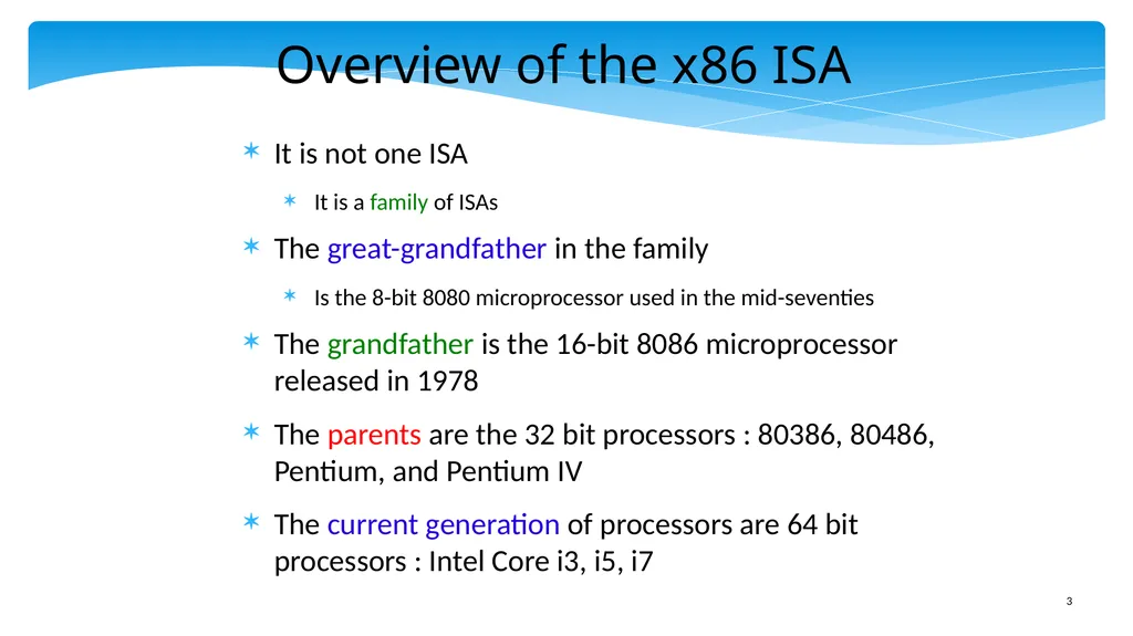
slide3. Overview of the x86 ISA It is not one ISA
It is a family of ISAs
The great-grandfather in the family
Is the 8-bit 8080 microprocessor used in the mid-seventies
The grandfather is the 16-bit 8086 microprocessor released in 1978
The parents are the 32 bit processors : 80386, 80486, Pentium, and Pentium IV
The current generation of processors are 64 bit processors : Intel Core i3, i5, i7<br>
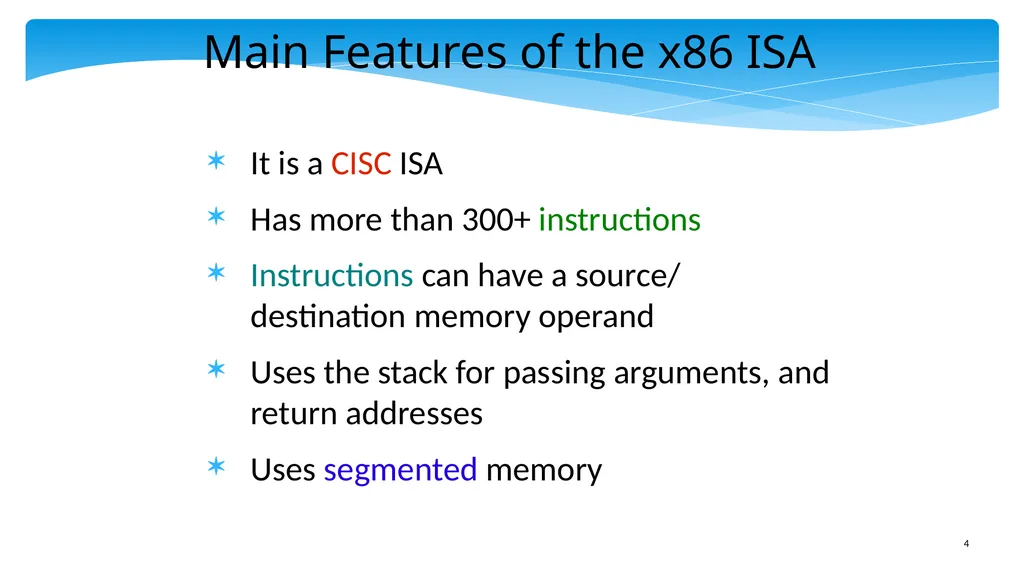
slide4. Main Features of the x86 ISA It is a CISC ISA
Has more than 300+ instructions
Instructions can have a source/ destination memory operand
Uses the stack for passing arguments, and return addresses
Uses segmented memory<br>
slide5. Outline x86 Machine Model
Simple Integer Instructions
Branch Instructions
Advanced Memory Instructions
Floating Point Instructions
Encoding the x86 ISA<br>
slide6. View of Registers Modern Intel machines are still ISA compatible with the arcane 16 bit 8086 processor
In fact, due to market requirements, a 64 bit processor needs to be ISA compatible with all 32 bit, and 16 bit ISAs
What do we do with registers?
Do we define a new set of registers for each type of x86 ISA? ANSWER : NO<br>
slide7. View of Registers – II Consider the 16 bit x86 ISA – It has 8 registers: ax, bx, cx, dx, sp, bp, si, di
Should we keep the old registers, and create a new set of registers in a 32 bit processor?
NO – Widen the 16 bit registers to 32 bits.
If the processor is running a 16 bit program, then it uses the lower 16 bits of every 32 bit register.<br>
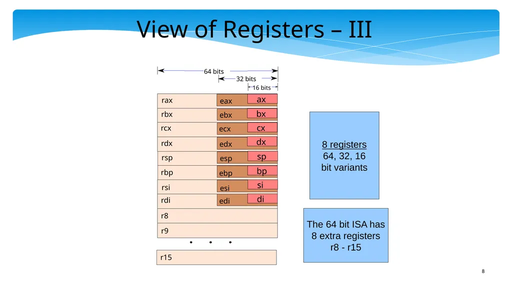
slide8. View of Registers – III The 64 bit ISA has
8 extra registers
r8 - r15 8 registers
64, 32, 16
bit variants eax ebx ecx edx esp ebp esi edi ax bx cx dx sp bp si di rax rbx rcx rdx rsp rbp rsi rdi r8 r9 r15 64 bits 32 bits 16 bits<br>
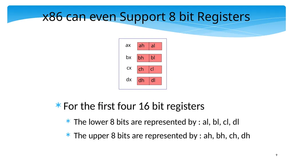
slide9. x86 can even Support 8 bit Registers For the first four 16 bit registers
The lower 8 bits are represented by : al, bl, cl, dl
The upper 8 bits are represented by : ah, bh, ch, dh ax bx cx dx ah al bh bl ch dh cl dl<br>
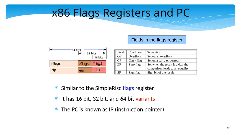
slide10. x86 Flags Registers and PC Similar to the SimpleRisc flags register
It has 16 bit, 32 bit, and 64 bit variants
The PC is known as IP (instruction pointer) Fields in the flags register<br>
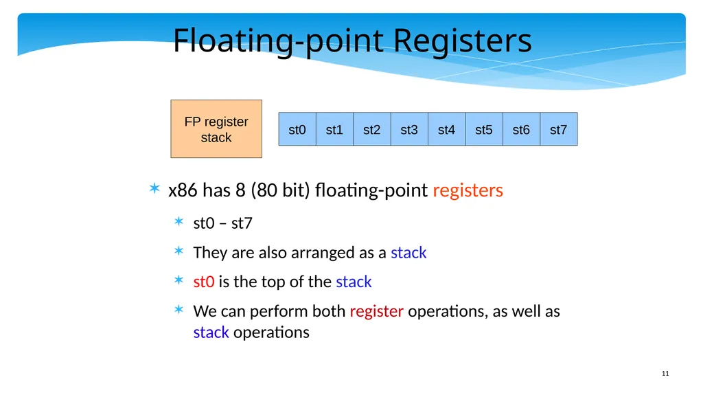
slide11. Floating-point Registers x86 has 8 (80 bit) floating-point registers
st0 – st7
They are also arranged as a stack
st0 is the top of the stack
We can perform both register operations, as well as stack operations st0 st1 st5 st4 st0 st0 st2 st3 st6 st7 FP register
stack<br>
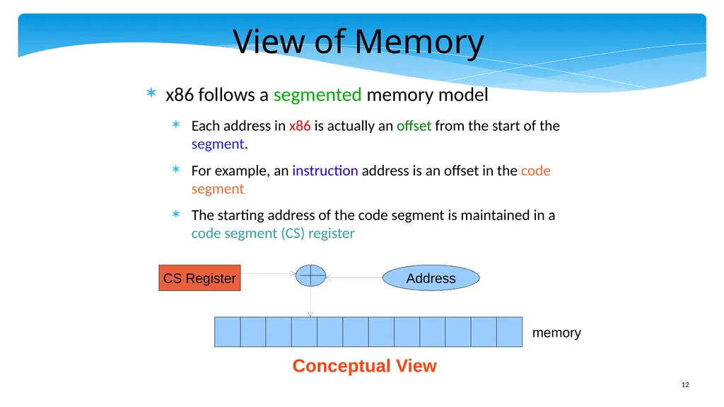
slide12. View of Memory x86 follows a segmented memory model
Each address in x86 is actually an offset from the start of the segment.
For example, an instruction address is an offset in the code segment
The starting address of the code segment is maintained in a code segment (CS) register memory CS Register Address Conceptual View<br>
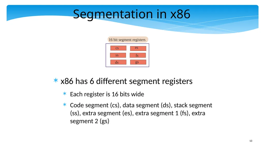
slide13. Segmentation in x86 x86 has 6 different segment registers
Each register is 16 bits wide
Code segment (cs), data segment (ds), stack segment (ss), extra segment (es), extra segment 1 (fs), extra segment 2 (gs)<br>
slide14. Segmented vs Linear Memory Model In a linear memory model (e.g. SimpleRisc, ARM) the address specified in the instruction is sent to the memory system
There are no segment registers
What are the advantages of a segmented memory model?
The contents of the segment registers can be changed by the operating system at runtime.
Can map the text section(code) to another part of memory, or in principle to other devices also (discussed in Chapter 10)
Stores cannot modify the instructions in the text section. REASON : Stores use the data segment, and instructions use the code segment<br>
slide15. How does Segmentation Work The segment registers nowadays contain an offset into a segment descriptor table
Because, 16 bits are not sufficient to store a memory address
Modern x86 processors have two kinds of segment descriptor tables
LDT (Local Descriptor Table), 1 per process, typically not used nowadays
GDT (Global Descriptor Table), contains 8191 entries
Each entry in these tables contains the starting address of the segment<br>
slide16. Segment Descriptor Cache Every memory access needs to access the GDT or LDT : VERY SLOW
Use a segment descriptor cache (SDC) at each processor that stores a copy of the relevant entries in the GDT
Lookup the SDC first
If an entry is not there, send a request to the GDT
Quick, fast, and efficient<br>
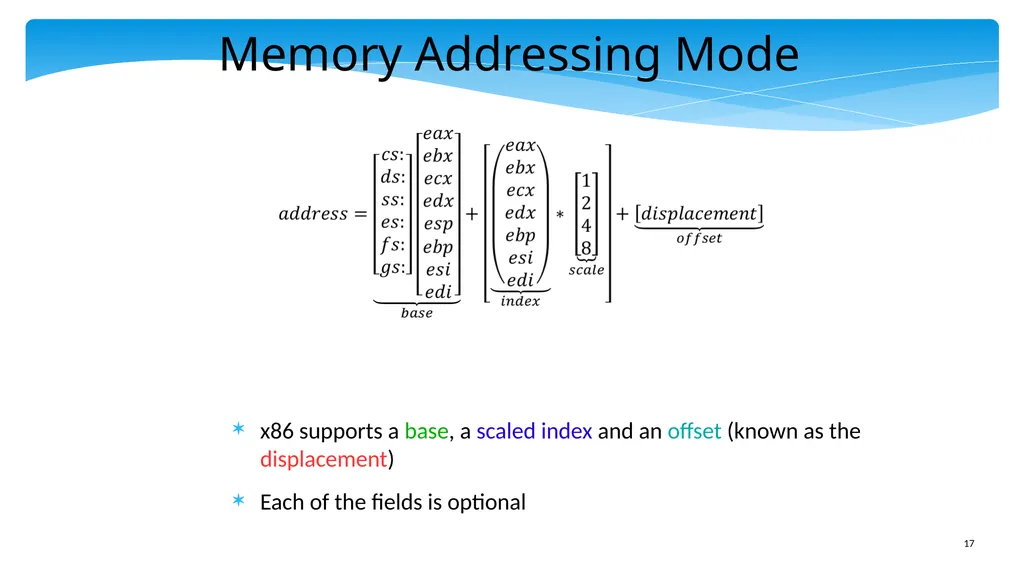
slide17. Memory Addressing Mode x86 supports a base, a scaled index and an offset (known as the displacement)
Each of the fields is optional<br>
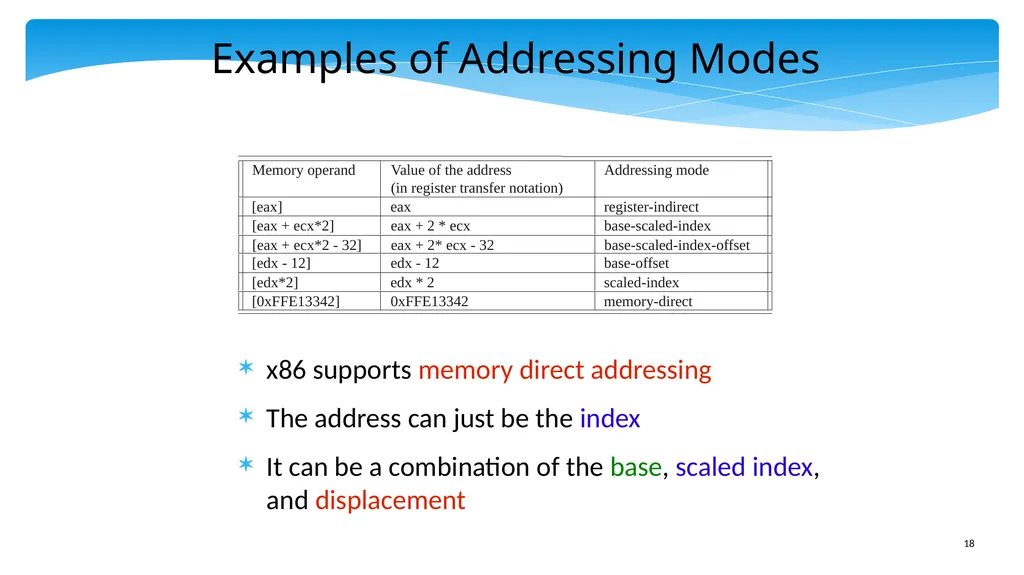
slide18. Examples of Addressing Modes x86 supports memory direct addressing
The address can just be the index
It can be a combination of the base, scaled index, and displacement<br>
slide19. Outline x86 Machine Model
Simple Integer Instructions
Branch Instructions
Advanced Memory Instructions
Floating Point Instructions
Encoding the x86 ISA<br>
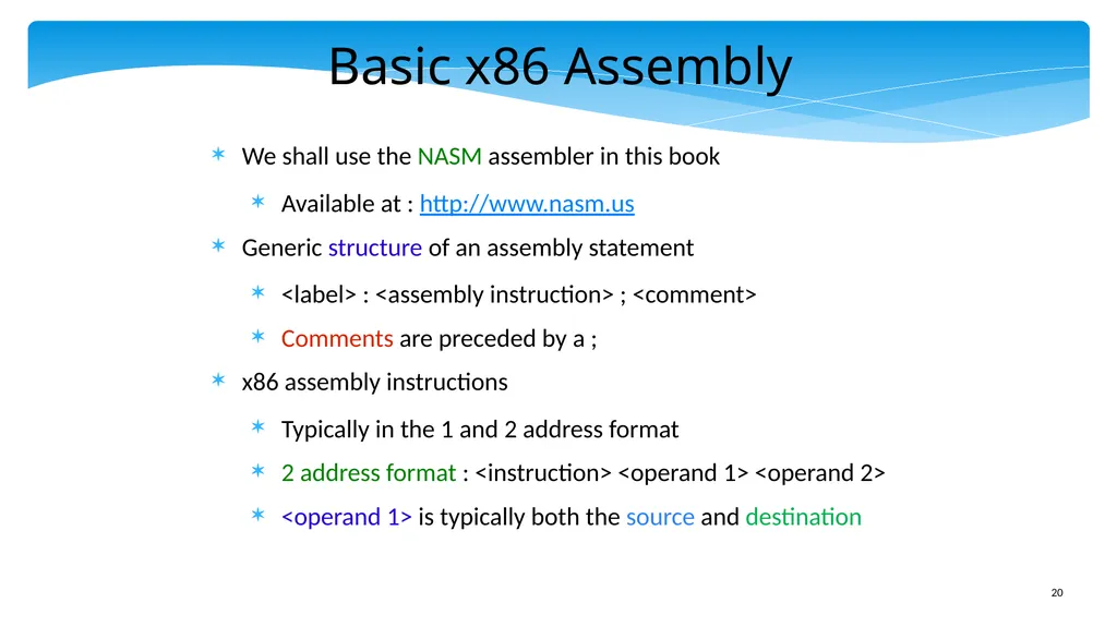
slide20. Basic x86 Assembly We shall use the NASM assembler in this book
Available at : http://www.nasm.us
Generic structure of an assembly statement
<label> : <assembly instruction> ; <comment>
Comments are preceded by a ;
x86 assembly instructions
Typically in the 1 and 2 address format
2 address format : <instruction> <operand 1> <operand 2>
<operand 1> is typically both the source and destination<br>
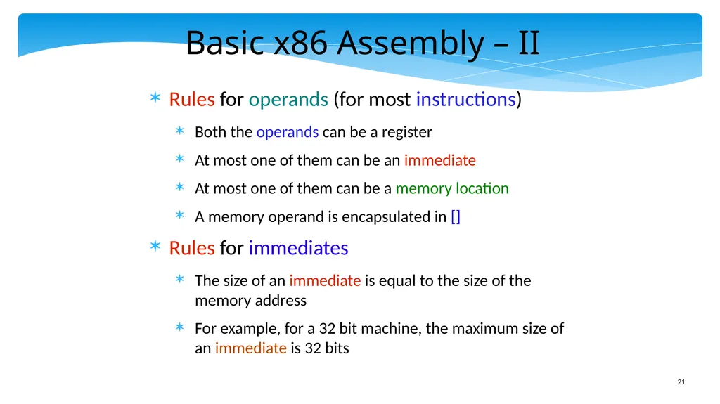
slide21. Basic x86 Assembly – II Rules for operands (for most instructions)
Both the operands can be a register
At most one of them can be an immediate
At most one of them can be a memory location
A memory operand is encapsulated in []
Rules for immediates
The size of an immediate is equal to the size of the memory address
For example, for a 32 bit machine, the maximum size of an immediate is 32 bits<br>
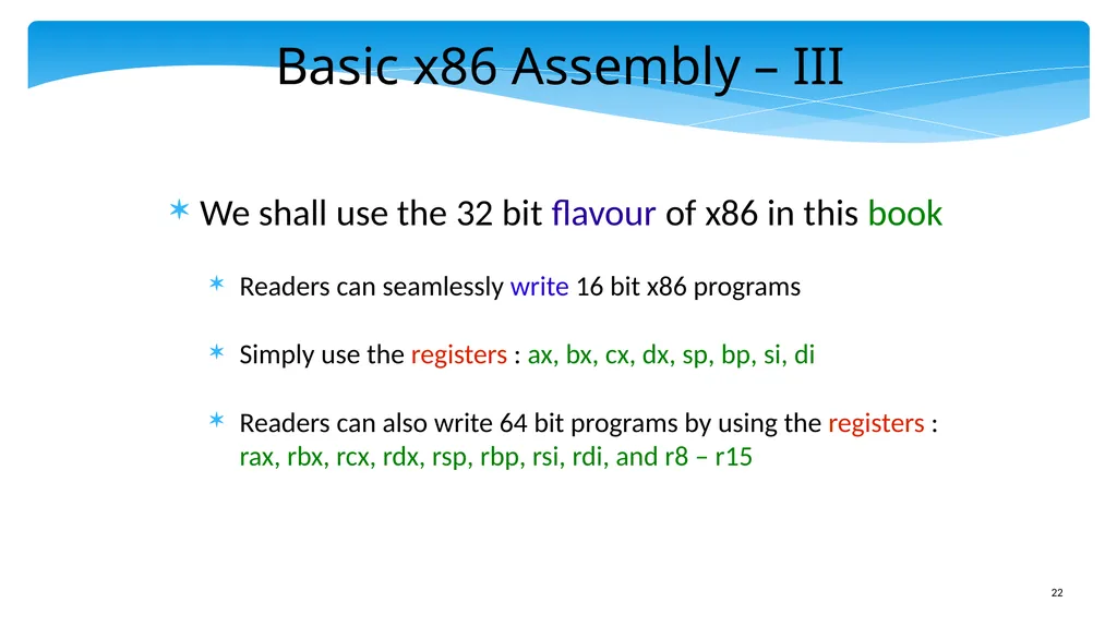
slide22. Basic x86 Assembly – III We shall use the 32 bit flavour of x86 in this book
Readers can seamlessly write 16 bit x86 programs
Simply use the registers : ax, bx, cx, dx, sp, bp, si, di
Readers can also write 64 bit programs by using the registers : rax, rbx, rcx, rdx, rsp, rbp, rsi, rdi, and r8 – r15<br>
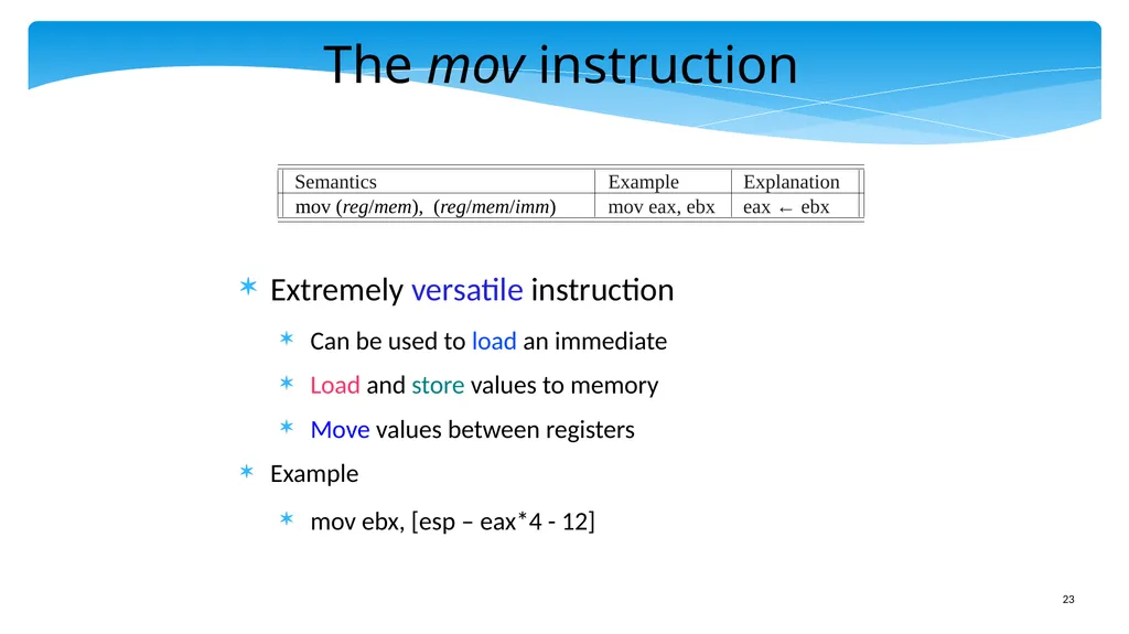
slide23. The mov instruction Extremely versatile instruction
Can be used to load an immediate
Load and store values to memory
Move values between registers
Example
mov ebx, [esp – eax*4 - 12]<br>
slide24. movsx and movzx instructions The regular mov instruction assumes that the source and destination have the same size
The movsx and movzx instructions replace the MSB bits by the sign bit, or zeros respectively<br>
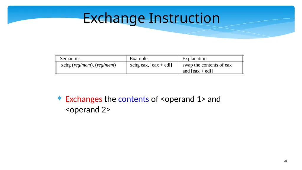
slide25. Exchange Instruction Exchanges the contents of <operand 1> and <operand 2> Semantics Example Explanation xchg (reg/mem), (reg/mem) xchg eax, [eax + edi] swap the contents of eax
and [eax + edi]<br>
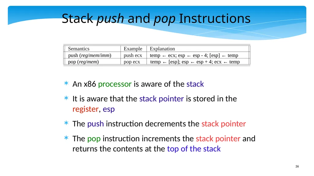
slide26. Stack push and pop Instructions An x86 processor is aware of the stack
It is aware that the stack pointer is stored in the register, esp
The push instruction decrements the stack pointer
The pop instruction increments the stack pointer and returns the contents at the top of the stack<br>
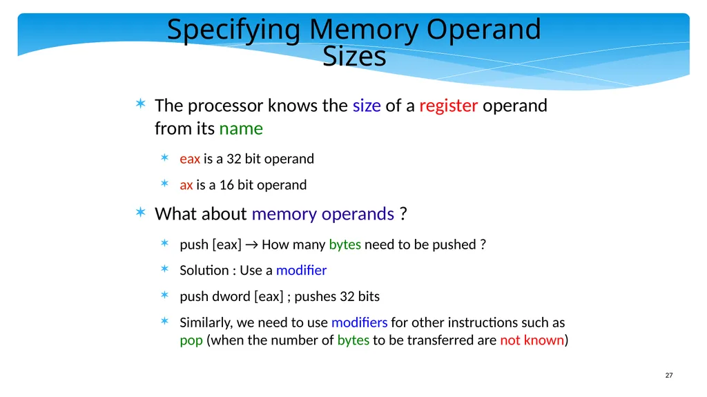
slide27. Specifying Memory Operand Sizes The processor knows the size of a register operand from its name
eax is a 32 bit operand
ax is a 16 bit operand
What about memory operands ?
push [eax] → How many bytes need to be pushed ?
Solution : Use a modifier
push dword [eax] ; pushes 32 bits
Similarly, we need to use modifiers for other instructions such as pop (when the number of bytes to be transferred are not known)<br>
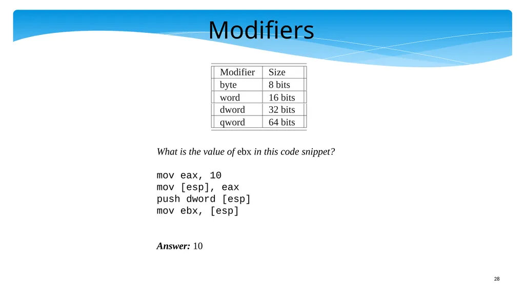
slide28. Modifiers What is the value of ebx in this code snippet?
mov eax, 10
mov [esp], eax
push dword [esp]
mov ebx, [esp]
Answer: 10<br>
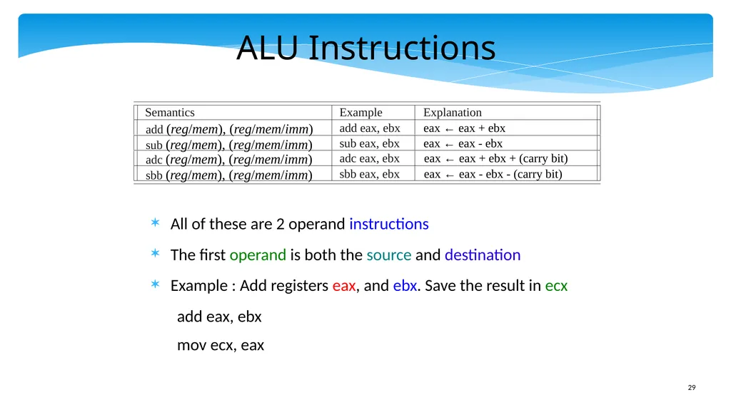
slide29. ALU Instructions All of these are 2 operand instructions
The first operand is both the source and destination
Example : Add registers eax, and ebx. Save the result in ecx
add eax, ebx
mov ecx, eax<br>
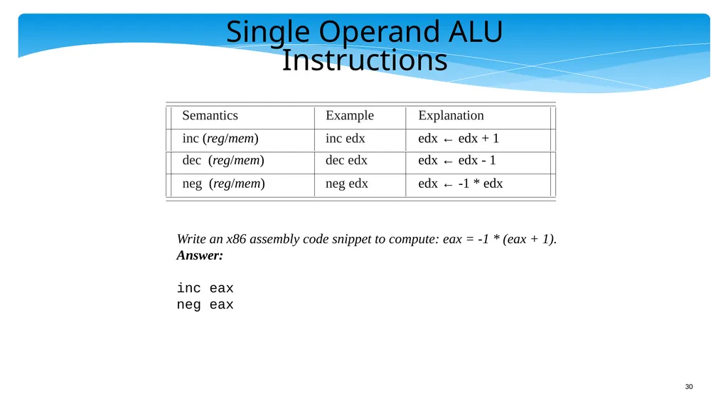
slide30. Single Operand ALU Instructions Write an x86 assembly code snippet to compute: eax = -1 * (eax + 1).
Answer:
inc eax
neg eax<br>
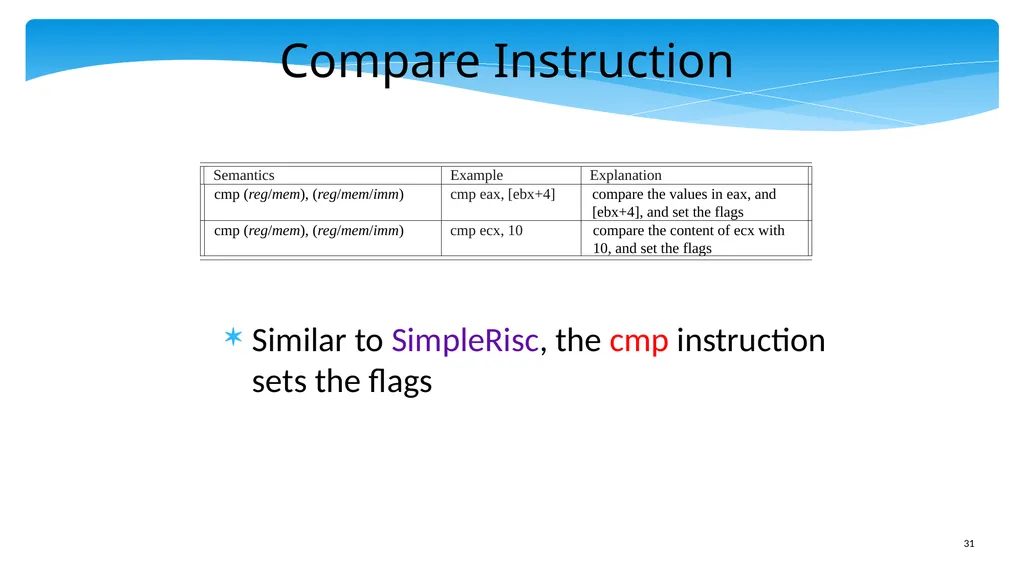
slide31. Compare Instruction Similar to SimpleRisc, the cmp instruction sets the flags<br>
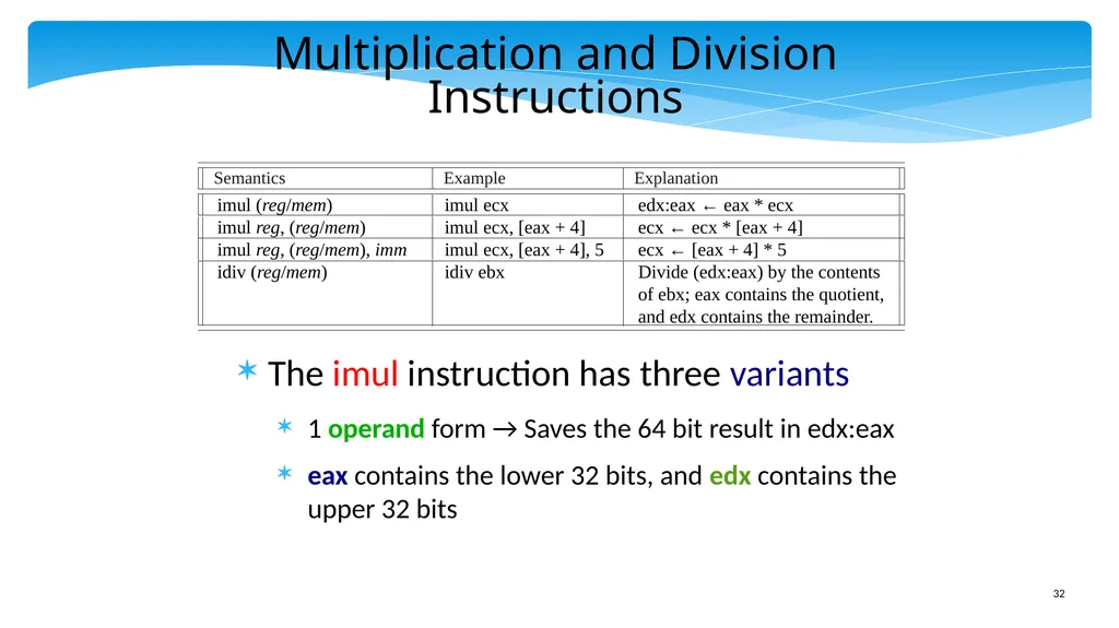
slide32. Multiplication and Division Instructions The imul instruction has three variants
1 operand form → Saves the 64 bit result in edx:eax
eax contains the lower 32 bits, and edx contains the upper 32 bits<br>
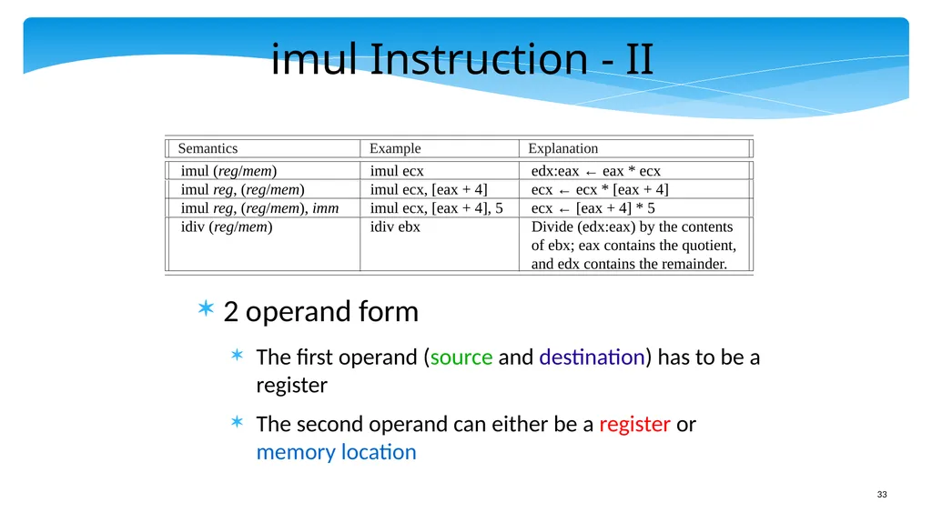
slide33. imul Instruction - II 2 operand form
The first operand (source and destination) has to be a register
The second operand can either be a register or memory location<br>
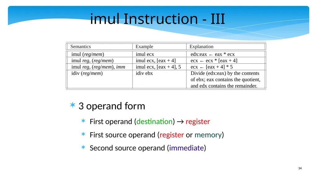
slide34. imul Instruction - III 3 operand form
First operand (destination) → register
First source operand (register or memory)
Second source operand (immediate)<br>
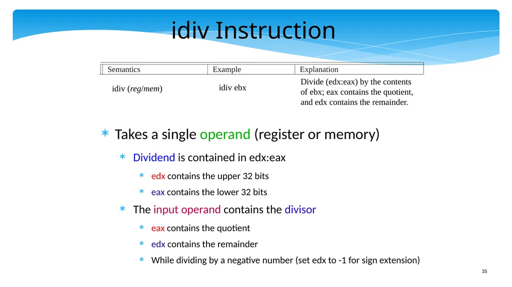
slide35. idiv Instruction Takes a single operand (register or memory)
Dividend is contained in edx:eax
edx contains the upper 32 bits
eax contains the lower 32 bits
The input operand contains the divisor
eax contains the quotient
edx contains the remainder
While dividing by a negative number (set edx to -1 for sign extension) Semantics Example Explanation idiv (reg/mem) idiv ebx Divide (edx:eax) by the contents
of ebx; eax contains the quotient,
and edx contains the remainder.<br>
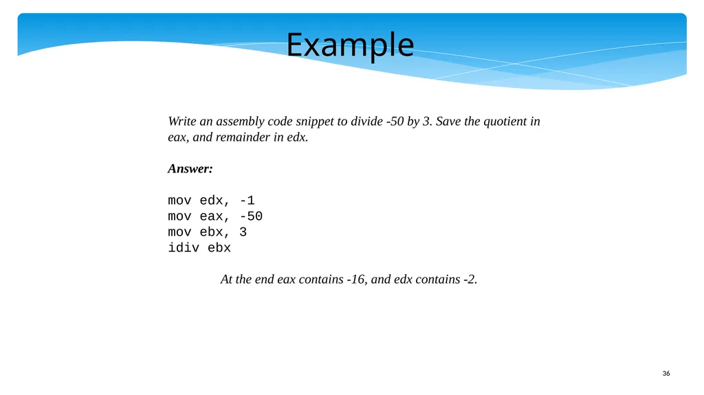
slide36. Example Write an assembly code snippet to divide -50 by 3. Save the quotient in
eax, and remainder in edx.
Answer:
mov edx, -1
mov eax, -50
mov ebx, 3
idiv ebx
At the end eax contains -16, and edx contains -2.<br>
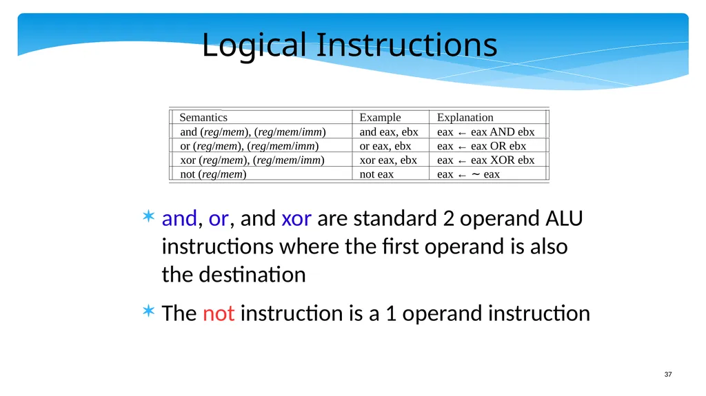
slide37. Logical Instructions and, or, and xor are standard 2 operand ALU instructions where the first operand is also the destination
The not instruction is a 1 operand instruction<br>
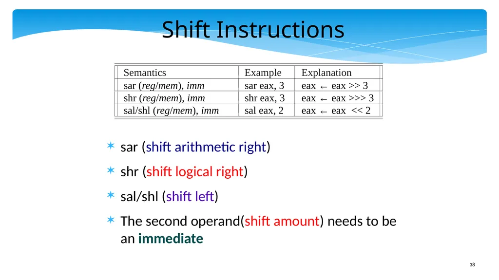
slide38. Shift Instructions sar (shift arithmetic right)
shr (shift logical right)
sal/shl (shift left)
The second operand(shift amount) needs to be an immediate<br>
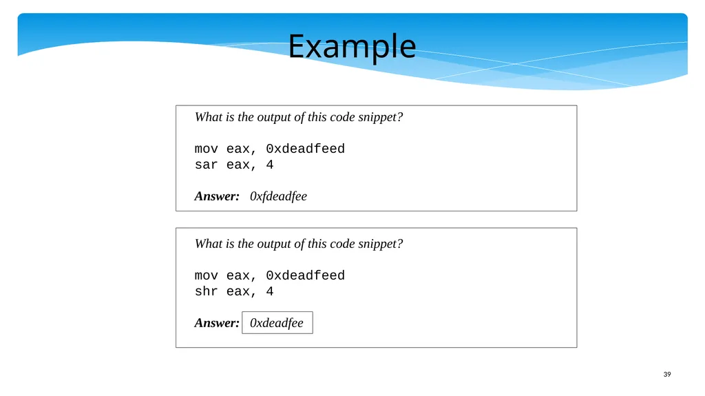
slide39. Example What is the output of this code snippet?
mov eax, 0xdeadfeed
sar eax, 4
Answer: 0xfdeadfee
What is the output of this code snippet?
mov eax, 0xdeadfeed
shr eax, 4
Answer: 0xdeadfee<br>
slide40. Outline x86 Machine Model
Simple Integer Instructions
Branch Instructions
Advanced Memory Instructions
Floating Point Instructions
Encoding the x86 ISA<br>
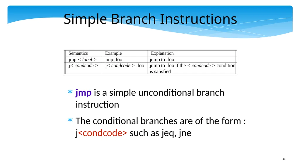
slide41. Simple Branch Instructions jmp is a simple unconditional branch instruction
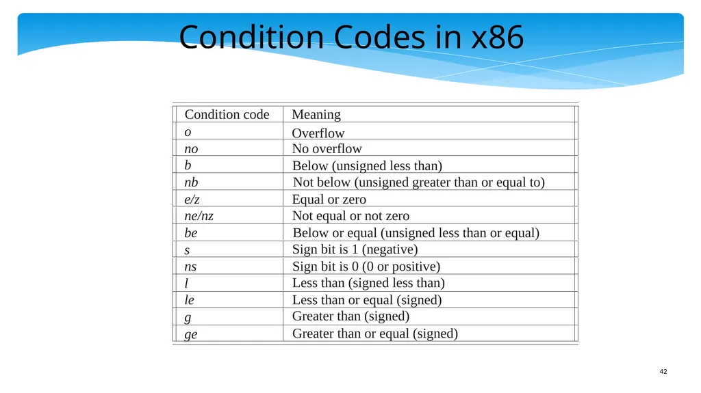
The conditional branches are of the form : j<condcode> such as jeq, jne<br>
slide42. Condition Codes in x86<br>
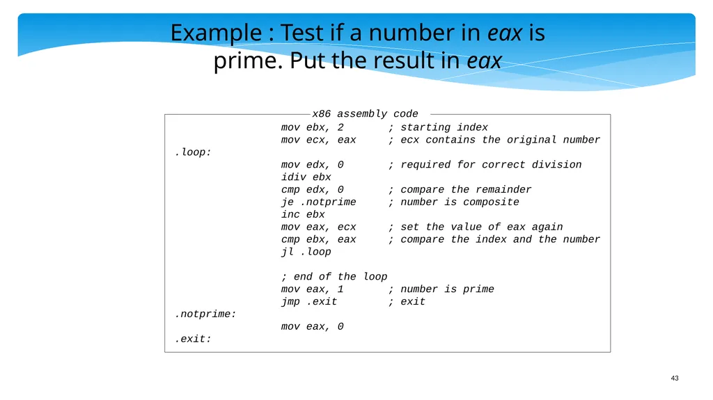
slide43. Example : Test if a number in eax is prime. Put the result in eax mov ebx, 2 ; starting index
mov ecx, eax ; ecx contains the original number
.loop:
mov edx, 0 ; required for correct division
idiv ebx
cmp edx, 0 ; compare the remainder
je .notprime ; number is composite
inc ebx
mov eax, ecx ; set the value of eax again
cmp ebx, eax ; compare the index and the number
jl .loop
; end of the loop
mov eax, 1 ; number is prime
jmp .exit ; exit
.notprime:
mov eax, 0
.exit:<br>
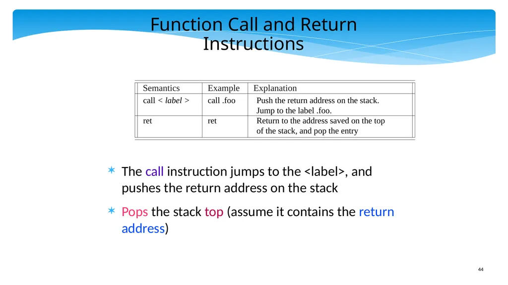
slide44. Function Call and Return Instructions The call instruction jumps to the <label>, and pushes the return address on the stack
Pops the stack top (assume it contains the return address)<br>
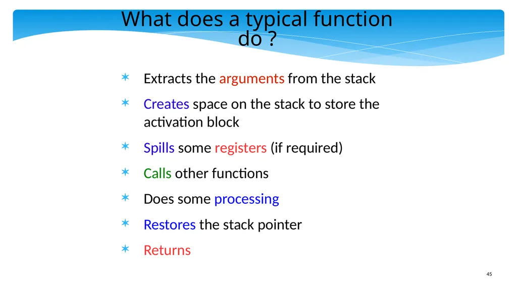
slide45. What does a typical function do ? Extracts the arguments from the stack
Creates space on the stack to store the activation block
Spills some registers (if required)
Calls other functions
Does some processing
Restores the stack pointer
Returns<br>
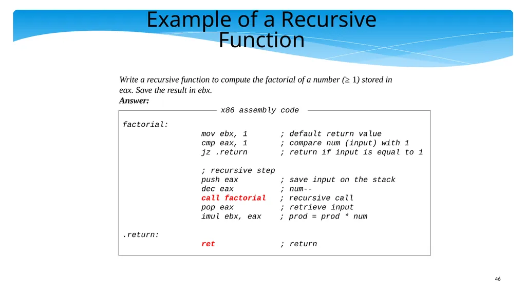
slide46. Write a recursive function to compute the factorial of a number (≥ 1) stored in eax. Save the result in ebx.
Answer: factorial:
mov ebx, 1 ; default return value
cmp eax, 1 ; compare num (input) with 1
jz .return ; return if input is equal to 1
; recursive step
push eax ; save input on the stack
dec eax ; num--
call factorial ; recursive call
pop eax ; retrieve input
imul ebx, eax ; prod = prod * num
.return:
ret ; return Example of a Recursive Function<br>
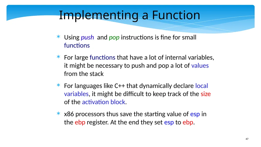
slide47. Implementing a Function Using push and pop instructions is fine for small functions
For large functions that have a lot of internal variables, it might be necessary to push and pop a lot of values from the stack
For languages like C++ that dynamically declare local variables, it might be difficult to keep track of the size of the activation block.
x86 processors thus save the starting value of esp in the ebp register. At the end they set esp to ebp.<br>
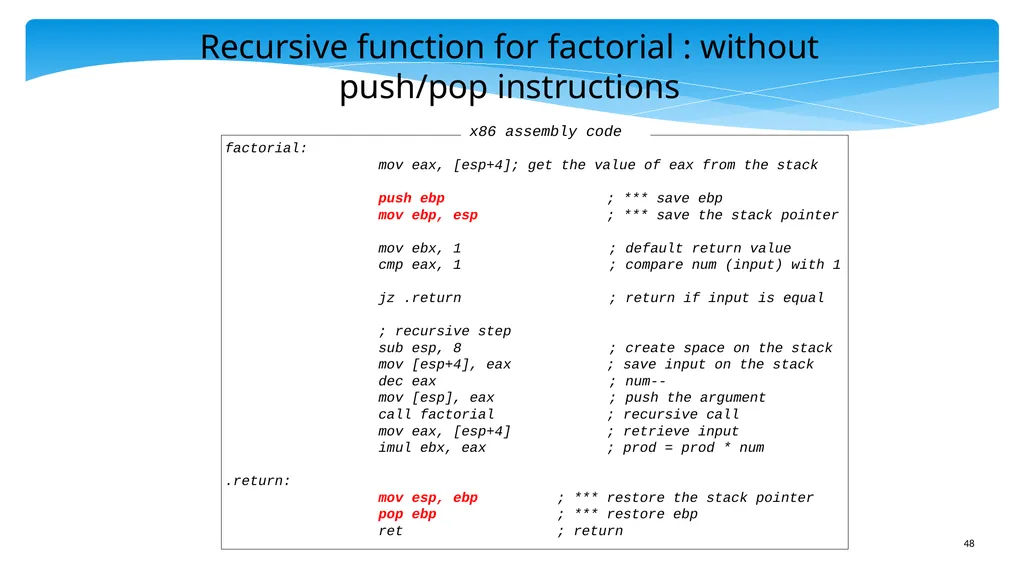
slide48. Recursive function for factorial : without push/pop instructions factorial:
mov eax, [esp+4]; get the value of eax from the stack
push ebp ; *** save ebp
mov ebp, esp ; *** save the stack pointer
mov ebx, 1 ; default return value
cmp eax, 1 ; compare num (input) with 1
jz .return ; return if input is equal
; recursive step
sub esp, 8 ; create space on the stack
mov [esp+4], eax ; save input on the stack
dec eax ; num--
mov [esp], eax ; push the argument
call factorial ; recursive call
mov eax, [esp+4] ; retrieve input
imul ebx, eax ; prod = prod * num
.return:
mov esp, ebp ; *** restore the stack pointer
pop ebp ; *** restore ebp
ret ; return<br>
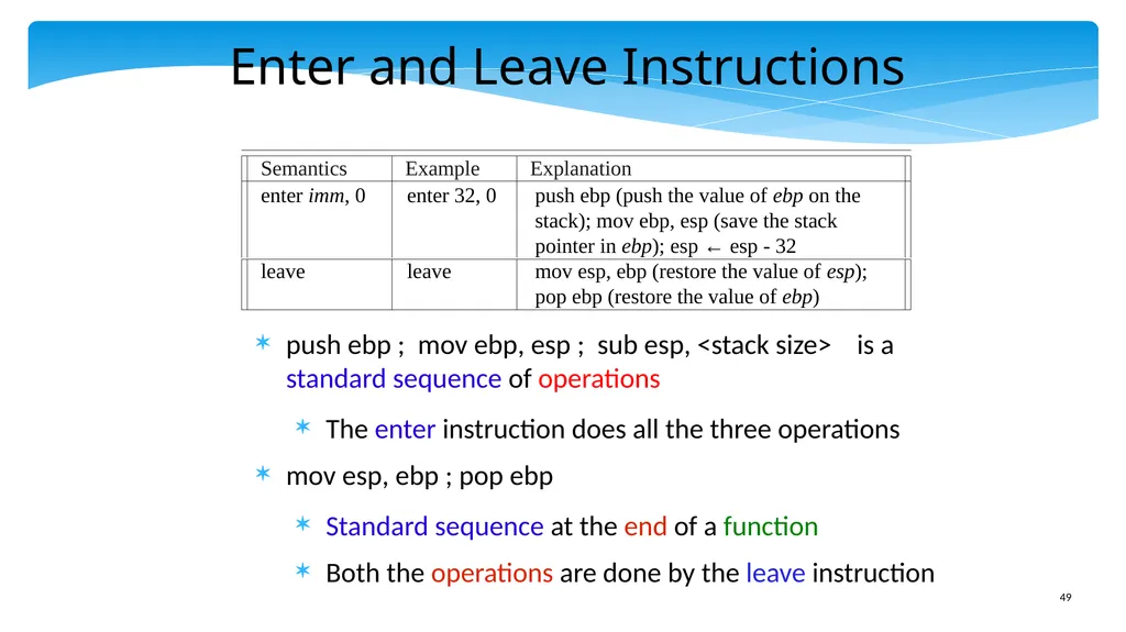
slide49. Enter and Leave Instructions push ebp ; mov ebp, esp ; sub esp, <stack size> is a standard sequence of operations
The enter instruction does all the three operations
mov esp, ebp ; pop ebp
Standard sequence at the end of a function
Both the operations are done by the leave instruction<br>
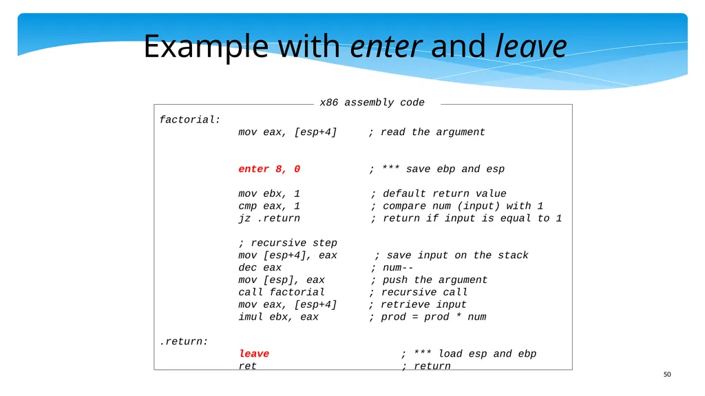
slide50. Example with enter and leave factorial:
mov eax, [esp+4] ; read the argument
enter 8, 0 ; *** save ebp and esp
mov ebx, 1 ; default return value
cmp eax, 1 ; compare num (input) with 1
jz .return ; return if input is equal to 1
; recursive step
mov [esp+4], eax ; save input on the stack
dec eax ; num--
mov [esp], eax ; push the argument
call factorial ; recursive call
mov eax, [esp+4] ; retrieve input
imul ebx, eax ; prod = prod * num
.return:
leave ; *** load esp and ebp
ret ; return<br>
slide51. Outline x86 Machine Model
Simple Integer Instructions
Branch Instructions
Advanced Memory Instructions
Floating Point Instructions
Encoding the x86 ISA<br>
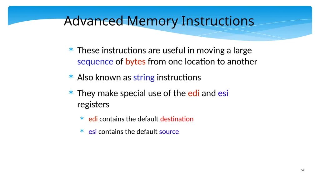
slide52. Advanced Memory Instructions These instructions are useful in moving a large sequence of bytes from one location to another
Also known as string instructions
They make special use of the edi and esi registers
edi contains the default destination
esi contains the default source<br>
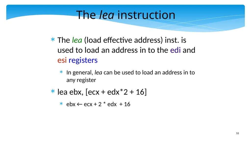
slide53. The lea instruction The lea (load effective address) inst. is used to load an address in to the edi and esi registers
In general, lea can be used to load an address in to any register
lea ebx, [ecx + edx*2 + 16]
ebx ← ecx + 2 * edx + 16<br>
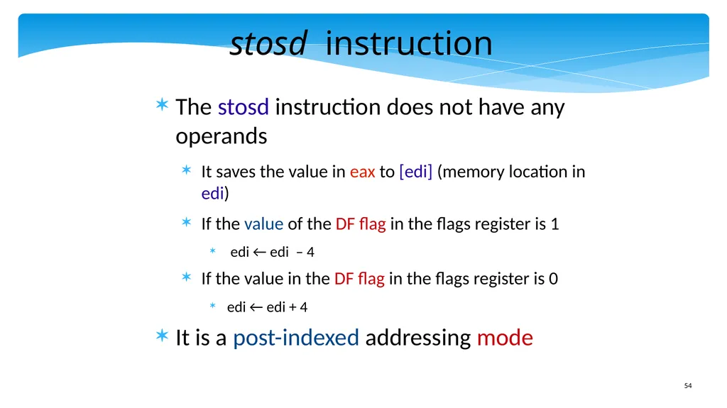
slide54. stosd instruction The stosd instruction does not have any operands
It saves the value in eax to [edi] (memory location in edi)
If the value of the DF flag in the flags register is 1
edi ← edi – 4
If the value in the DF flag in the flags register is 0
edi ← edi + 4
It is a post-indexed addressing mode<br>
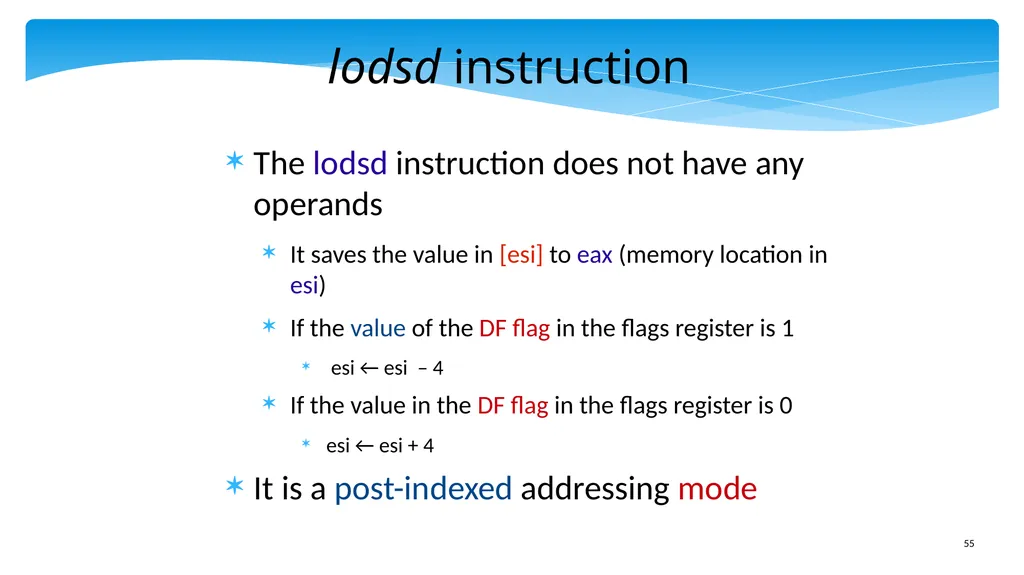
slide55. lodsd instruction The lodsd instruction does not have any operands
It saves the value in [esi] to eax (memory location in esi)
If the value of the DF flag in the flags register is 1
esi ← esi – 4
If the value in the DF flag in the flags register is 0
esi ← esi + 4
It is a post-indexed addressing mode<br>
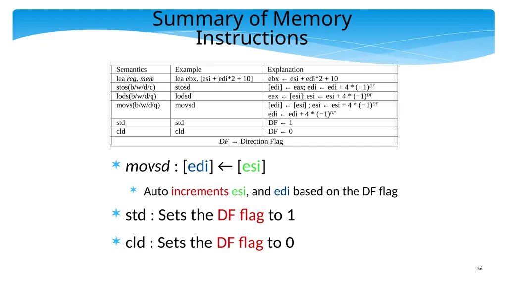
slide56. Summary of Memory Instructions movsd : [edi] ← [esi]
Auto increments esi, and edi based on the DF flag
std : Sets the DF flag to 1
cld : Sets the DF flag to 0<br>
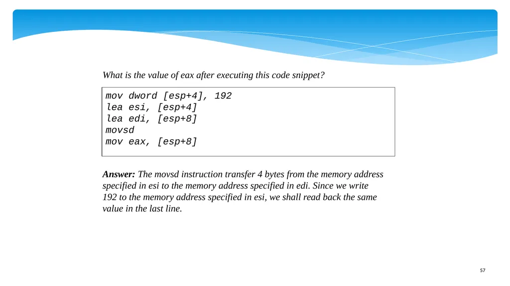
slide57. What is the value of eax after executing this code snippet? Answer: The movsd instruction transfer 4 bytes from the memory address
specified in esi to the memory address specified in edi. Since we write
192 to the memory address specified in esi, we shall read back the same
value in the last line. mov dword [esp+4], 192
lea esi, [esp+4]
lea edi, [esp+8]
movsd
mov eax, [esp+8]<br>
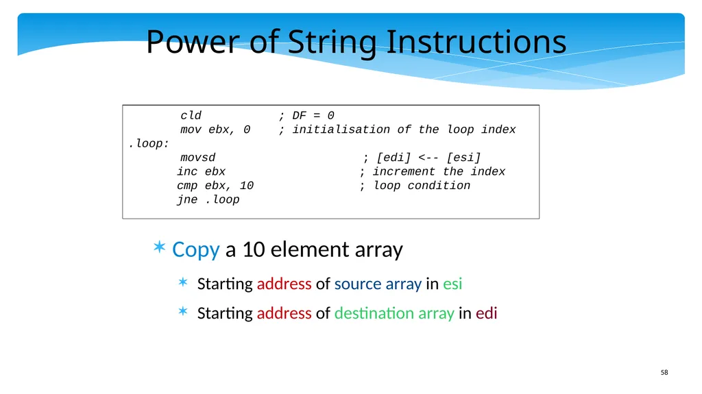
slide58. Power of String Instructions Copy a 10 element array
Starting address of source array in esi
Starting address of destination array in edi cld ; DF = 0
mov ebx, 0 ; initialisation of the loop index
.loop:
movsd ; [edi] <-- [esi]
inc ebx ; increment the index
cmp ebx, 10 ; loop condition
jne .loop<br>
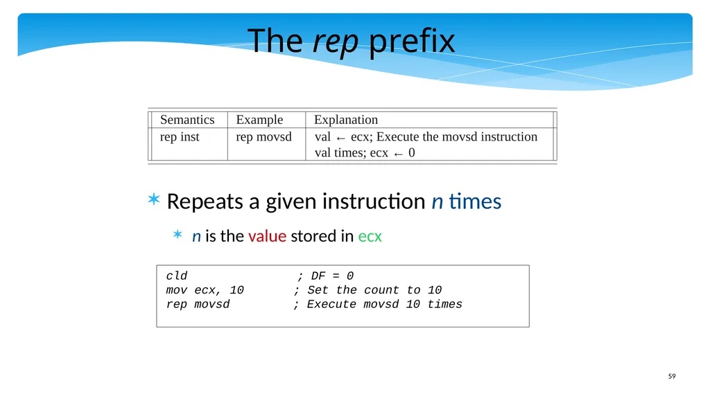
slide59. The rep prefix Repeats a given instruction n times
n is the value stored in ecx cld ; DF = 0
mov ecx, 10 ; Set the count to 10
rep movsd ; Execute movsd 10 times<br>
slide60. Outline x86 Machine Model
Simple Integer Instructions
Branch Instructions
Advanced Memory Instructions
Floating Point Instructions
Encoding the x86 ISA<br>
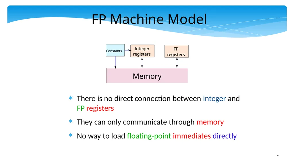
slide61. FP Machine Model There is no direct connection between integer and FP registers
They can only communicate through memory
No way to load floating-point immediates directly<br>
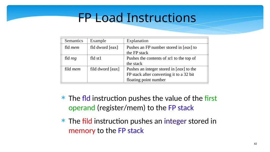
slide62. FP Load Instructions The fld instruction pushes the value of the first operand (register/mem) to the FP stack
The fild instruction pushes an integer stored in memory to the FP stack<br>
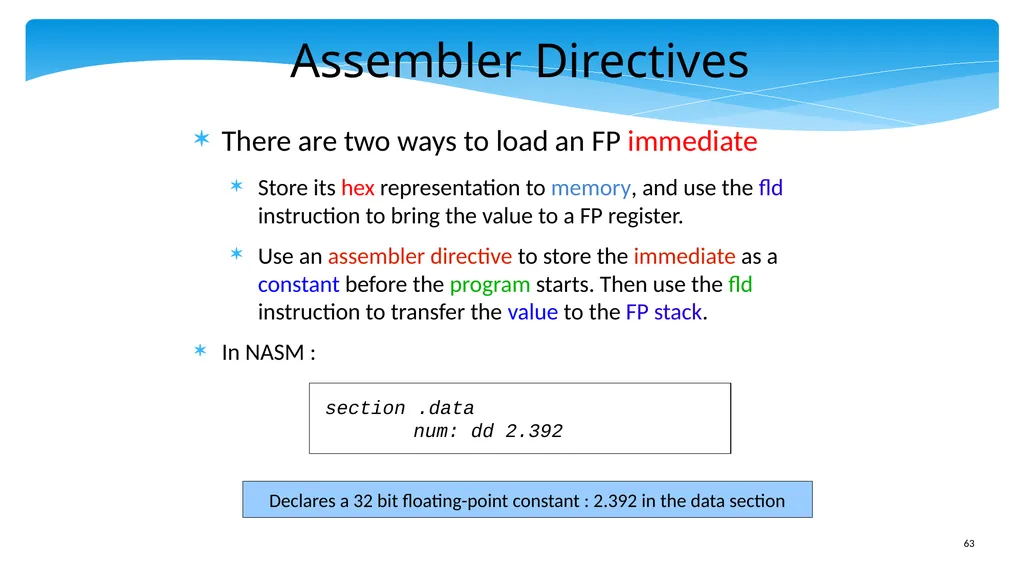
slide63. Assembler Directives There are two ways to load an FP immediate
Store its hex representation to memory, and use the fld instruction to bring the value to a FP register.
Use an assembler directive to store the immediate as a constant before the program starts. Then use the fld instruction to transfer the value to the FP stack.
In NASM : Declares a 32 bit floating-point constant : 2.392 in the data section section .data
num: dd 2.392<br>
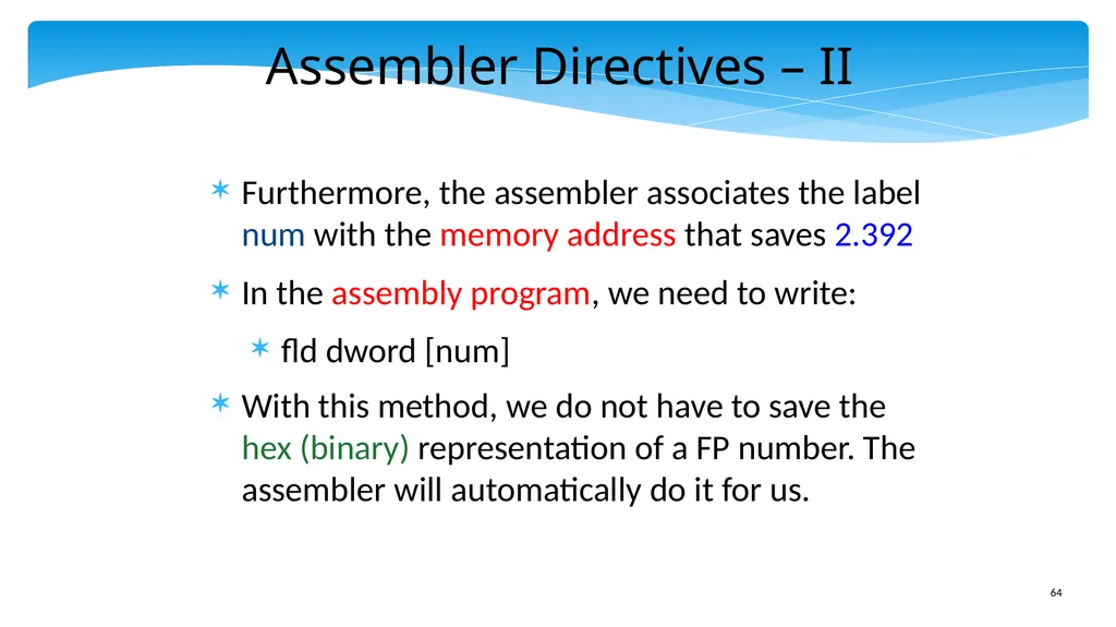
slide64. Assembler Directives – II Furthermore, the assembler associates the label num with the memory address that saves 2.392
In the assembly program, we need to write:
fld dword [num]
With this method, we do not have to save the hex (binary) representation of a FP number. The assembler will automatically do it for us.<br>
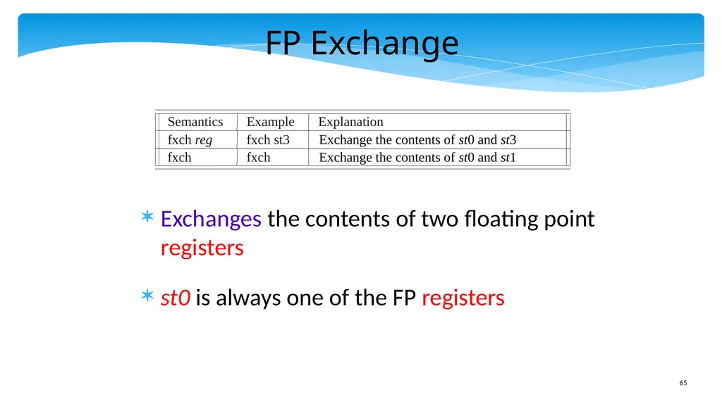
slide65. FP Exchange Exchanges the contents of two floating point registers
st0 is always one of the FP registers<br>
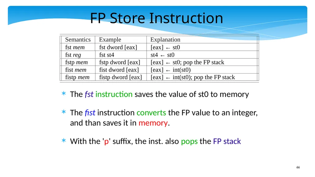
slide66. FP Store Instruction The fst instruction saves the value of st0 to memory
The fist instruction converts the FP value to an integer, and than saves it in memory.
With the 'p' suffix, the inst. also pops the FP stack<br>
slide67. Example A 32 bit floating point number is loaded in st0. Convert it to an integer and save its value in eax.
Answer:
fist dword[esp+4] ; save st0 to [esp+4]
mov eax, [esp+4]<br>
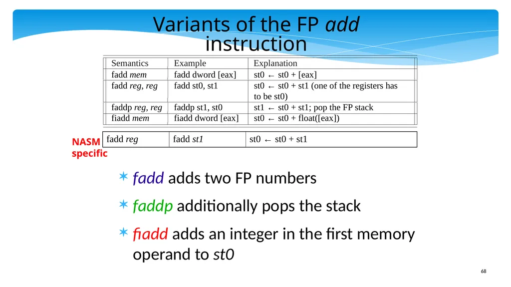
slide68. Variants of the FP add instruction fadd adds two FP numbers
faddp additionally pops the stack
fiadd adds an integer in the first memory operand to st0 NASM
specific<br>
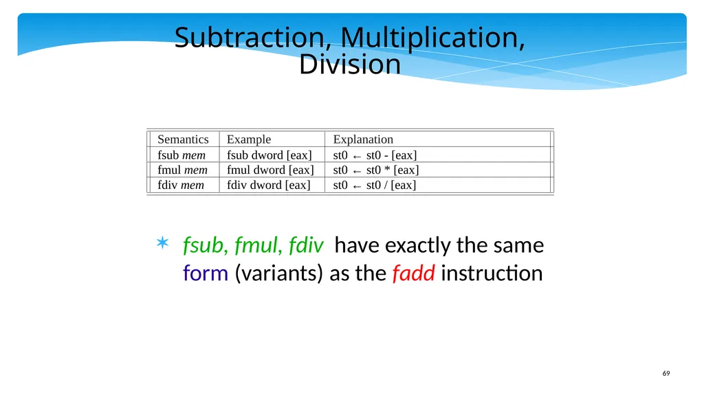
slide69. Subtraction, Multiplication, Division fsub, fmul, fdiv have exactly the same form (variants) as the fadd instruction<br>
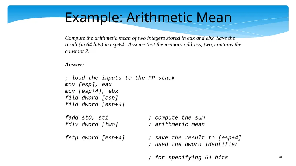
slide70. Example: Arithmetic Mean Compute the arithmetic mean of two integers stored in eax and ebx. Save the result (in 64 bits) in esp+4. Assume that the memory address, two, contains the constant 2.
Answer:
; load the inputs to the FP stack
mov [esp], eax
mov [esp+4], ebx
fild dword [esp]
fild dword [esp+4]
fadd st0, st1 ; compute the sum
fdiv dword [two] ; arithmetic mean
fstp qword [esp+4] ; save the result to [esp+4]
; used the qword identifier
; for specifying 64 bits<br>
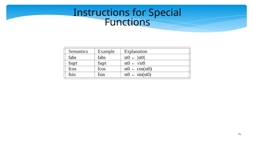
slide71. Instructions for Special Functions<br>
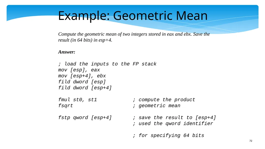
slide72. Example: Geometric Mean Compute the geometric mean of two integers stored in eax and ebx. Save the result (in 64 bits) in esp+4.
Answer:
; load the inputs to the FP stack
mov [esp], eax
mov [esp+4], ebx
fild dword [esp]
fild dword [esp+4]
fmul st0, st1 ; compute the product
fsqrt ; geometric mean
fstp qword [esp+4] ; save the result to [esp+4]
; used the qword identifier
; for specifying 64 bits<br>
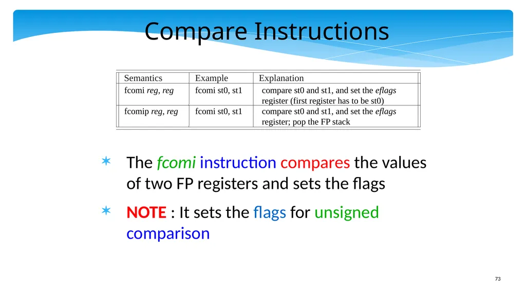
slide73. Compare Instructions The fcomi instruction compares the values of two FP registers and sets the flags
NOTE : It sets the flags for unsigned comparison<br>
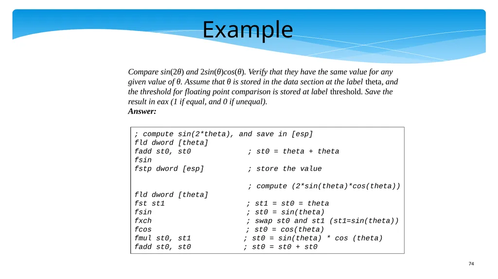
slide74. Example Compare sin(2θ) and 2sin(θ)cos(θ). Verify that they have the same value for any given value of θ. Assume that θ is stored in the data section at the label theta, and the threshold for floating point comparison is stored at label threshold. Save the result in eax (1 if equal, and 0 if unequal).
Answer: ; compute sin(2*theta), and save in [esp]
fld dword [theta]
fadd st0, st0 ; st0 = theta + theta
fsin
fstp dword [esp] ; store the value
; compute (2*sin(theta)*cos(theta))
fld dword [theta]
fst st1 ; st1 = st0 = theta
fsin ; st0 = sin(theta)
fxch ; swap st0 and st1 (st1=sin(theta))
fcos ; st0 = cos(theta)
fmul st0, st1 ; st0 = sin(theta) * cos (theta)
fadd st0, st0 ; st0 = st0 + st0<br>
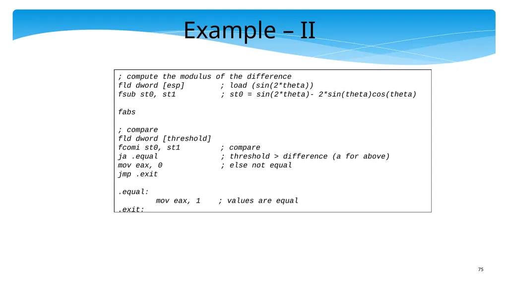
slide75. Example – II ; compute the modulus of the difference
fld dword [esp] ; load (sin(2*theta))
fsub st0, st1 ; st0 = sin(2*theta)- 2*sin(theta)cos(theta)
fabs
; compare
fld dword [threshold]
fcomi st0, st1 ; compare
ja .equal ; threshold > difference (a for above)
mov eax, 0 ; else not equal
jmp .exit
.equal:
mov eax, 1 ; values are equal
.exit:<br>
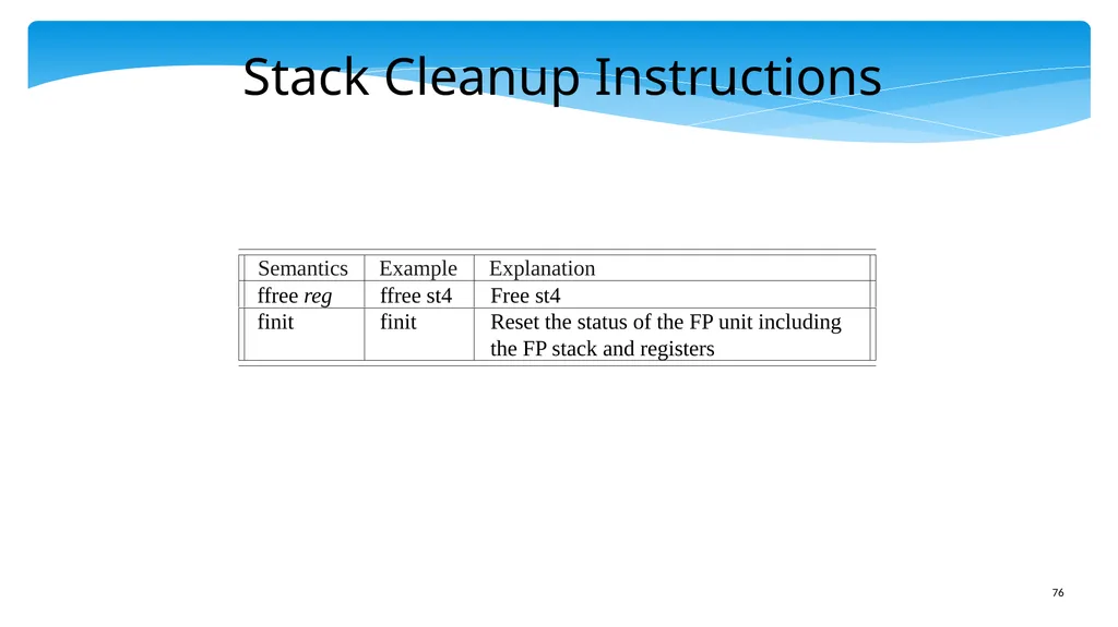
slide76. Stack Cleanup Instructions<br>
slide77. Outline x86 Machine Model
Simple Integer Instructions
Branch Instructions
Advanced Memory Instructions
Floating Point Instructions
Encoding the x86 ISA<br>
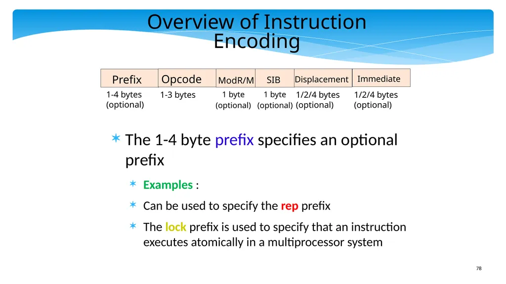
slide78. Overview of Instruction Encoding The 1-4 byte prefix specifies an optional prefix
Examples :
Can be used to specify the rep prefix
The lock prefix is used to specify that an instruction executes atomically in a multiprocessor system<br>
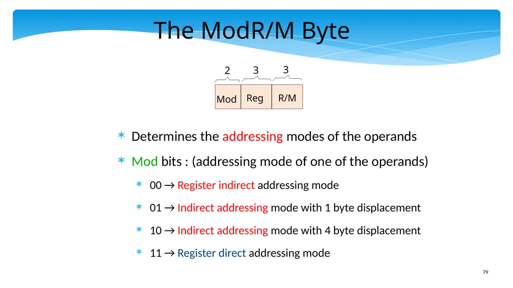
slide79. The ModR/M Byte Determines the addressing modes of the operands
Mod bits : (addressing mode of one of the operands)
00 → Register indirect addressing mode
01 → Indirect addressing mode with 1 byte displacement
10 → Indirect addressing mode with 4 byte displacement
11 → Register direct addressing mode<br>
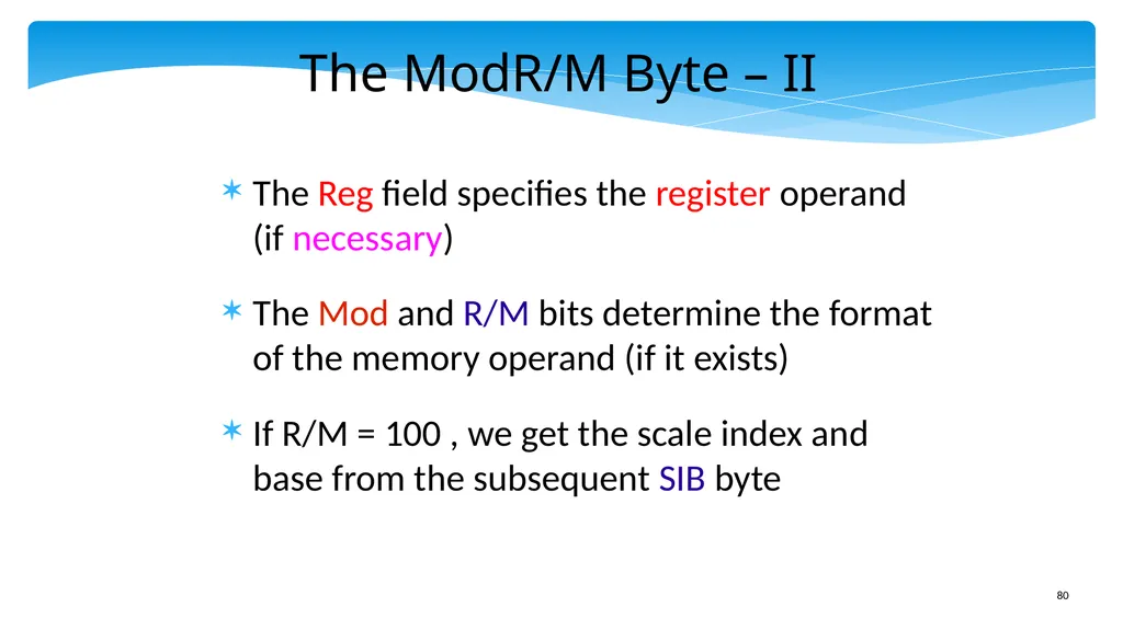
slide80. The ModR/M Byte – II The Reg field specifies the register operand (if necessary)
The Mod and R/M bits determine the format of the memory operand (if it exists)
If R/M = 100 , we get the scale index and base from the subsequent SIB byte<br>
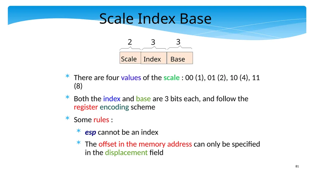
slide81. Scale Index Base There are four values of the scale : 00 (1), 01 (2), 10 (4), 11 (8)
Both the index and base are 3 bits each, and follow the register encoding scheme
Some rules :
esp cannot be an index
The offset in the memory address can only be specified in the displacement field Scale 2 3 3 Index Base<br>
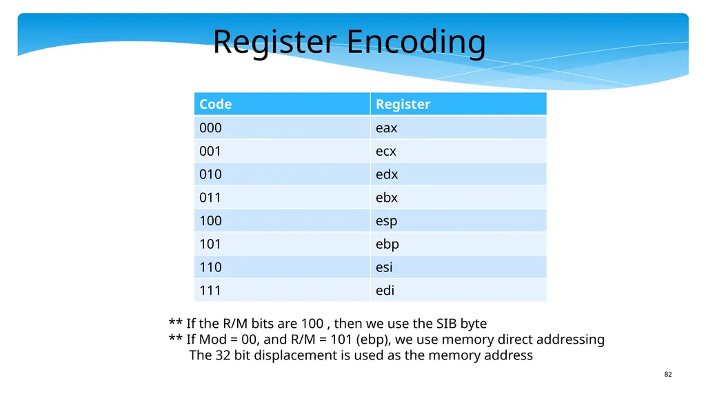
slide82. Register Encoding ** If the R/M bits are 100 , then we use the SIB byte
** If Mod = 00, and R/M = 101 (ebp), we use memory direct addressing The 32 bit displacement is used as the memory address<br>
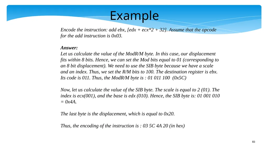
slide83. Example Encode the instruction: add ebx, [edx + ecx*2 + 32]. Assume that the opcode
for the add instruction is 0x03.
Answer:
Let us calculate the value of the ModR/M byte. In this case, our displacement fits within 8 bits. Hence, we can set the Mod bits equal to 01 (corresponding to an 8 bit displacement). We need to use the SIB byte because we have a scale and an index. Thus, we set the R/M bits to 100. The destination register is ebx. Its code is 011. Thus, the ModR/M byte is : 01 011 100 (0x5C)
Now, let us calculate the value of the SIB byte. The scale is equal to 2 (01). The index is ecx(001), and the base is edx (010). Hence, the SIB byte is: 01 001 010 = 0x4A.
The last byte is the displacement, which is equal to 0x20.
Thus, the encoding of the instruction is : 03 5C 4A 20 (in hex)<br>
slide84. THE END<br>
slide2. Download the pdf of the book www.basiccomparch.com videos Slides, software, solution manual Print version
(Publisher: WhiteFalcon, 2021)
Available on e-commerce sites. The pdf version of the book and all the learning resources can be freely downloaded from the website: www.basiccomparch.com 2nd version<br>
slide3. Overview of the x86 ISA It is not one ISA
It is a family of ISAs
The great-grandfather in the family
Is the 8-bit 8080 microprocessor used in the mid-seventies
The grandfather is the 16-bit 8086 microprocessor released in 1978
The parents are the 32 bit processors : 80386, 80486, Pentium, and Pentium IV
The current generation of processors are 64 bit processors : Intel Core i3, i5, i7<br>
slide4. Main Features of the x86 ISA It is a CISC ISA
Has more than 300+ instructions
Instructions can have a source/ destination memory operand
Uses the stack for passing arguments, and return addresses
Uses segmented memory<br>
slide5. Outline x86 Machine Model
Simple Integer Instructions
Branch Instructions
Advanced Memory Instructions
Floating Point Instructions
Encoding the x86 ISA<br>
slide6. View of Registers Modern Intel machines are still ISA compatible with the arcane 16 bit 8086 processor
In fact, due to market requirements, a 64 bit processor needs to be ISA compatible with all 32 bit, and 16 bit ISAs
What do we do with registers?
Do we define a new set of registers for each type of x86 ISA? ANSWER : NO<br>
slide7. View of Registers – II Consider the 16 bit x86 ISA – It has 8 registers: ax, bx, cx, dx, sp, bp, si, di
Should we keep the old registers, and create a new set of registers in a 32 bit processor?
NO – Widen the 16 bit registers to 32 bits.
If the processor is running a 16 bit program, then it uses the lower 16 bits of every 32 bit register.<br>
slide8. View of Registers – III The 64 bit ISA has
8 extra registers
r8 - r15 8 registers
64, 32, 16
bit variants eax ebx ecx edx esp ebp esi edi ax bx cx dx sp bp si di rax rbx rcx rdx rsp rbp rsi rdi r8 r9 r15 64 bits 32 bits 16 bits<br>
slide9. x86 can even Support 8 bit Registers For the first four 16 bit registers
The lower 8 bits are represented by : al, bl, cl, dl
The upper 8 bits are represented by : ah, bh, ch, dh ax bx cx dx ah al bh bl ch dh cl dl<br>
slide10. x86 Flags Registers and PC Similar to the SimpleRisc flags register
It has 16 bit, 32 bit, and 64 bit variants
The PC is known as IP (instruction pointer) Fields in the flags register<br>
slide11. Floating-point Registers x86 has 8 (80 bit) floating-point registers
st0 – st7
They are also arranged as a stack
st0 is the top of the stack
We can perform both register operations, as well as stack operations st0 st1 st5 st4 st0 st0 st2 st3 st6 st7 FP register
stack<br>
slide12. View of Memory x86 follows a segmented memory model
Each address in x86 is actually an offset from the start of the segment.
For example, an instruction address is an offset in the code segment
The starting address of the code segment is maintained in a code segment (CS) register memory CS Register Address Conceptual View<br>
slide13. Segmentation in x86 x86 has 6 different segment registers
Each register is 16 bits wide
Code segment (cs), data segment (ds), stack segment (ss), extra segment (es), extra segment 1 (fs), extra segment 2 (gs)<br>
slide14. Segmented vs Linear Memory Model In a linear memory model (e.g. SimpleRisc, ARM) the address specified in the instruction is sent to the memory system
There are no segment registers
What are the advantages of a segmented memory model?
The contents of the segment registers can be changed by the operating system at runtime.
Can map the text section(code) to another part of memory, or in principle to other devices also (discussed in Chapter 10)
Stores cannot modify the instructions in the text section. REASON : Stores use the data segment, and instructions use the code segment<br>
slide15. How does Segmentation Work The segment registers nowadays contain an offset into a segment descriptor table
Because, 16 bits are not sufficient to store a memory address
Modern x86 processors have two kinds of segment descriptor tables
LDT (Local Descriptor Table), 1 per process, typically not used nowadays
GDT (Global Descriptor Table), contains 8191 entries
Each entry in these tables contains the starting address of the segment<br>
slide16. Segment Descriptor Cache Every memory access needs to access the GDT or LDT : VERY SLOW
Use a segment descriptor cache (SDC) at each processor that stores a copy of the relevant entries in the GDT
Lookup the SDC first
If an entry is not there, send a request to the GDT
Quick, fast, and efficient<br>
slide17. Memory Addressing Mode x86 supports a base, a scaled index and an offset (known as the displacement)
Each of the fields is optional<br>
slide18. Examples of Addressing Modes x86 supports memory direct addressing
The address can just be the index
It can be a combination of the base, scaled index, and displacement<br>
slide19. Outline x86 Machine Model
Simple Integer Instructions
Branch Instructions
Advanced Memory Instructions
Floating Point Instructions
Encoding the x86 ISA<br>
slide20. Basic x86 Assembly We shall use the NASM assembler in this book
Available at : http://www.nasm.us
Generic structure of an assembly statement
<label> : <assembly instruction> ; <comment>
Comments are preceded by a ;
x86 assembly instructions
Typically in the 1 and 2 address format
2 address format : <instruction> <operand 1> <operand 2>
<operand 1> is typically both the source and destination<br>
slide21. Basic x86 Assembly – II Rules for operands (for most instructions)
Both the operands can be a register
At most one of them can be an immediate
At most one of them can be a memory location
A memory operand is encapsulated in []
Rules for immediates
The size of an immediate is equal to the size of the memory address
For example, for a 32 bit machine, the maximum size of an immediate is 32 bits<br>
slide22. Basic x86 Assembly – III We shall use the 32 bit flavour of x86 in this book
Readers can seamlessly write 16 bit x86 programs
Simply use the registers : ax, bx, cx, dx, sp, bp, si, di
Readers can also write 64 bit programs by using the registers : rax, rbx, rcx, rdx, rsp, rbp, rsi, rdi, and r8 – r15<br>
slide23. The mov instruction Extremely versatile instruction
Can be used to load an immediate
Load and store values to memory
Move values between registers
Example
mov ebx, [esp – eax*4 - 12]<br>
slide24. movsx and movzx instructions The regular mov instruction assumes that the source and destination have the same size
The movsx and movzx instructions replace the MSB bits by the sign bit, or zeros respectively<br>
slide25. Exchange Instruction Exchanges the contents of <operand 1> and <operand 2> Semantics Example Explanation xchg (reg/mem), (reg/mem) xchg eax, [eax + edi] swap the contents of eax
and [eax + edi]<br>
slide26. Stack push and pop Instructions An x86 processor is aware of the stack
It is aware that the stack pointer is stored in the register, esp
The push instruction decrements the stack pointer
The pop instruction increments the stack pointer and returns the contents at the top of the stack<br>
slide27. Specifying Memory Operand Sizes The processor knows the size of a register operand from its name
eax is a 32 bit operand
ax is a 16 bit operand
What about memory operands ?
push [eax] → How many bytes need to be pushed ?
Solution : Use a modifier
push dword [eax] ; pushes 32 bits
Similarly, we need to use modifiers for other instructions such as pop (when the number of bytes to be transferred are not known)<br>
slide28. Modifiers What is the value of ebx in this code snippet?
mov eax, 10
mov [esp], eax
push dword [esp]
mov ebx, [esp]
Answer: 10<br>
slide29. ALU Instructions All of these are 2 operand instructions
The first operand is both the source and destination
Example : Add registers eax, and ebx. Save the result in ecx
add eax, ebx
mov ecx, eax<br>
slide30. Single Operand ALU Instructions Write an x86 assembly code snippet to compute: eax = -1 * (eax + 1).
Answer:
inc eax
neg eax<br>
slide31. Compare Instruction Similar to SimpleRisc, the cmp instruction sets the flags<br>
slide32. Multiplication and Division Instructions The imul instruction has three variants
1 operand form → Saves the 64 bit result in edx:eax
eax contains the lower 32 bits, and edx contains the upper 32 bits<br>
slide33. imul Instruction - II 2 operand form
The first operand (source and destination) has to be a register
The second operand can either be a register or memory location<br>
slide34. imul Instruction - III 3 operand form
First operand (destination) → register
First source operand (register or memory)
Second source operand (immediate)<br>
slide35. idiv Instruction Takes a single operand (register or memory)
Dividend is contained in edx:eax
edx contains the upper 32 bits
eax contains the lower 32 bits
The input operand contains the divisor
eax contains the quotient
edx contains the remainder
While dividing by a negative number (set edx to -1 for sign extension) Semantics Example Explanation idiv (reg/mem) idiv ebx Divide (edx:eax) by the contents
of ebx; eax contains the quotient,
and edx contains the remainder.<br>
slide36. Example Write an assembly code snippet to divide -50 by 3. Save the quotient in
eax, and remainder in edx.
Answer:
mov edx, -1
mov eax, -50
mov ebx, 3
idiv ebx
At the end eax contains -16, and edx contains -2.<br>
slide37. Logical Instructions and, or, and xor are standard 2 operand ALU instructions where the first operand is also the destination
The not instruction is a 1 operand instruction<br>
slide38. Shift Instructions sar (shift arithmetic right)
shr (shift logical right)
sal/shl (shift left)
The second operand(shift amount) needs to be an immediate<br>
slide39. Example What is the output of this code snippet?
mov eax, 0xdeadfeed
sar eax, 4
Answer: 0xfdeadfee
What is the output of this code snippet?
mov eax, 0xdeadfeed
shr eax, 4
Answer: 0xdeadfee<br>
slide40. Outline x86 Machine Model
Simple Integer Instructions
Branch Instructions
Advanced Memory Instructions
Floating Point Instructions
Encoding the x86 ISA<br>
slide41. Simple Branch Instructions jmp is a simple unconditional branch instruction
The conditional branches are of the form : j<condcode> such as jeq, jne<br>
slide42. Condition Codes in x86<br>
slide43. Example : Test if a number in eax is prime. Put the result in eax mov ebx, 2 ; starting index
mov ecx, eax ; ecx contains the original number
.loop:
mov edx, 0 ; required for correct division
idiv ebx
cmp edx, 0 ; compare the remainder
je .notprime ; number is composite
inc ebx
mov eax, ecx ; set the value of eax again
cmp ebx, eax ; compare the index and the number
jl .loop
; end of the loop
mov eax, 1 ; number is prime
jmp .exit ; exit
.notprime:
mov eax, 0
.exit:<br>
slide44. Function Call and Return Instructions The call instruction jumps to the <label>, and pushes the return address on the stack
Pops the stack top (assume it contains the return address)<br>
slide45. What does a typical function do ? Extracts the arguments from the stack
Creates space on the stack to store the activation block
Spills some registers (if required)
Calls other functions
Does some processing
Restores the stack pointer
Returns<br>
slide46. Write a recursive function to compute the factorial of a number (≥ 1) stored in eax. Save the result in ebx.
Answer: factorial:
mov ebx, 1 ; default return value
cmp eax, 1 ; compare num (input) with 1
jz .return ; return if input is equal to 1
; recursive step
push eax ; save input on the stack
dec eax ; num--
call factorial ; recursive call
pop eax ; retrieve input
imul ebx, eax ; prod = prod * num
.return:
ret ; return Example of a Recursive Function<br>
slide47. Implementing a Function Using push and pop instructions is fine for small functions
For large functions that have a lot of internal variables, it might be necessary to push and pop a lot of values from the stack
For languages like C++ that dynamically declare local variables, it might be difficult to keep track of the size of the activation block.
x86 processors thus save the starting value of esp in the ebp register. At the end they set esp to ebp.<br>
slide48. Recursive function for factorial : without push/pop instructions factorial:
mov eax, [esp+4]; get the value of eax from the stack
push ebp ; *** save ebp
mov ebp, esp ; *** save the stack pointer
mov ebx, 1 ; default return value
cmp eax, 1 ; compare num (input) with 1
jz .return ; return if input is equal
; recursive step
sub esp, 8 ; create space on the stack
mov [esp+4], eax ; save input on the stack
dec eax ; num--
mov [esp], eax ; push the argument
call factorial ; recursive call
mov eax, [esp+4] ; retrieve input
imul ebx, eax ; prod = prod * num
.return:
mov esp, ebp ; *** restore the stack pointer
pop ebp ; *** restore ebp
ret ; return<br>
slide49. Enter and Leave Instructions push ebp ; mov ebp, esp ; sub esp, <stack size> is a standard sequence of operations
The enter instruction does all the three operations
mov esp, ebp ; pop ebp
Standard sequence at the end of a function
Both the operations are done by the leave instruction<br>
slide50. Example with enter and leave factorial:
mov eax, [esp+4] ; read the argument
enter 8, 0 ; *** save ebp and esp
mov ebx, 1 ; default return value
cmp eax, 1 ; compare num (input) with 1
jz .return ; return if input is equal to 1
; recursive step
mov [esp+4], eax ; save input on the stack
dec eax ; num--
mov [esp], eax ; push the argument
call factorial ; recursive call
mov eax, [esp+4] ; retrieve input
imul ebx, eax ; prod = prod * num
.return:
leave ; *** load esp and ebp
ret ; return<br>
slide51. Outline x86 Machine Model
Simple Integer Instructions
Branch Instructions
Advanced Memory Instructions
Floating Point Instructions
Encoding the x86 ISA<br>
slide52. Advanced Memory Instructions These instructions are useful in moving a large sequence of bytes from one location to another
Also known as string instructions
They make special use of the edi and esi registers
edi contains the default destination
esi contains the default source<br>
slide53. The lea instruction The lea (load effective address) inst. is used to load an address in to the edi and esi registers
In general, lea can be used to load an address in to any register
lea ebx, [ecx + edx*2 + 16]
ebx ← ecx + 2 * edx + 16<br>
slide54. stosd instruction The stosd instruction does not have any operands
It saves the value in eax to [edi] (memory location in edi)
If the value of the DF flag in the flags register is 1
edi ← edi – 4
If the value in the DF flag in the flags register is 0
edi ← edi + 4
It is a post-indexed addressing mode<br>
slide55. lodsd instruction The lodsd instruction does not have any operands
It saves the value in [esi] to eax (memory location in esi)
If the value of the DF flag in the flags register is 1
esi ← esi – 4
If the value in the DF flag in the flags register is 0
esi ← esi + 4
It is a post-indexed addressing mode<br>
slide56. Summary of Memory Instructions movsd : [edi] ← [esi]
Auto increments esi, and edi based on the DF flag
std : Sets the DF flag to 1
cld : Sets the DF flag to 0<br>
slide57. What is the value of eax after executing this code snippet? Answer: The movsd instruction transfer 4 bytes from the memory address
specified in esi to the memory address specified in edi. Since we write
192 to the memory address specified in esi, we shall read back the same
value in the last line. mov dword [esp+4], 192
lea esi, [esp+4]
lea edi, [esp+8]
movsd
mov eax, [esp+8]<br>
slide58. Power of String Instructions Copy a 10 element array
Starting address of source array in esi
Starting address of destination array in edi cld ; DF = 0
mov ebx, 0 ; initialisation of the loop index
.loop:
movsd ; [edi] <-- [esi]
inc ebx ; increment the index
cmp ebx, 10 ; loop condition
jne .loop<br>
slide59. The rep prefix Repeats a given instruction n times
n is the value stored in ecx cld ; DF = 0
mov ecx, 10 ; Set the count to 10
rep movsd ; Execute movsd 10 times<br>
slide60. Outline x86 Machine Model
Simple Integer Instructions
Branch Instructions
Advanced Memory Instructions
Floating Point Instructions
Encoding the x86 ISA<br>
slide61. FP Machine Model There is no direct connection between integer and FP registers
They can only communicate through memory
No way to load floating-point immediates directly<br>
slide62. FP Load Instructions The fld instruction pushes the value of the first operand (register/mem) to the FP stack
The fild instruction pushes an integer stored in memory to the FP stack<br>
slide63. Assembler Directives There are two ways to load an FP immediate
Store its hex representation to memory, and use the fld instruction to bring the value to a FP register.
Use an assembler directive to store the immediate as a constant before the program starts. Then use the fld instruction to transfer the value to the FP stack.
In NASM : Declares a 32 bit floating-point constant : 2.392 in the data section section .data
num: dd 2.392<br>
slide64. Assembler Directives – II Furthermore, the assembler associates the label num with the memory address that saves 2.392
In the assembly program, we need to write:
fld dword [num]
With this method, we do not have to save the hex (binary) representation of a FP number. The assembler will automatically do it for us.<br>
slide65. FP Exchange Exchanges the contents of two floating point registers
st0 is always one of the FP registers<br>
slide66. FP Store Instruction The fst instruction saves the value of st0 to memory
The fist instruction converts the FP value to an integer, and than saves it in memory.
With the 'p' suffix, the inst. also pops the FP stack<br>
slide67. Example A 32 bit floating point number is loaded in st0. Convert it to an integer and save its value in eax.
Answer:
fist dword[esp+4] ; save st0 to [esp+4]
mov eax, [esp+4]<br>
slide68. Variants of the FP add instruction fadd adds two FP numbers
faddp additionally pops the stack
fiadd adds an integer in the first memory operand to st0 NASM
specific<br>
slide69. Subtraction, Multiplication, Division fsub, fmul, fdiv have exactly the same form (variants) as the fadd instruction<br>
slide70. Example: Arithmetic Mean Compute the arithmetic mean of two integers stored in eax and ebx. Save the result (in 64 bits) in esp+4. Assume that the memory address, two, contains the constant 2.
Answer:
; load the inputs to the FP stack
mov [esp], eax
mov [esp+4], ebx
fild dword [esp]
fild dword [esp+4]
fadd st0, st1 ; compute the sum
fdiv dword [two] ; arithmetic mean
fstp qword [esp+4] ; save the result to [esp+4]
; used the qword identifier
; for specifying 64 bits<br>
slide71. Instructions for Special Functions<br>
slide72. Example: Geometric Mean Compute the geometric mean of two integers stored in eax and ebx. Save the result (in 64 bits) in esp+4.
Answer:
; load the inputs to the FP stack
mov [esp], eax
mov [esp+4], ebx
fild dword [esp]
fild dword [esp+4]
fmul st0, st1 ; compute the product
fsqrt ; geometric mean
fstp qword [esp+4] ; save the result to [esp+4]
; used the qword identifier
; for specifying 64 bits<br>
slide73. Compare Instructions The fcomi instruction compares the values of two FP registers and sets the flags
NOTE : It sets the flags for unsigned comparison<br>
slide74. Example Compare sin(2θ) and 2sin(θ)cos(θ). Verify that they have the same value for any given value of θ. Assume that θ is stored in the data section at the label theta, and the threshold for floating point comparison is stored at label threshold. Save the result in eax (1 if equal, and 0 if unequal).
Answer: ; compute sin(2*theta), and save in [esp]
fld dword [theta]
fadd st0, st0 ; st0 = theta + theta
fsin
fstp dword [esp] ; store the value
; compute (2*sin(theta)*cos(theta))
fld dword [theta]
fst st1 ; st1 = st0 = theta
fsin ; st0 = sin(theta)
fxch ; swap st0 and st1 (st1=sin(theta))
fcos ; st0 = cos(theta)
fmul st0, st1 ; st0 = sin(theta) * cos (theta)
fadd st0, st0 ; st0 = st0 + st0<br>
slide75. Example – II ; compute the modulus of the difference
fld dword [esp] ; load (sin(2*theta))
fsub st0, st1 ; st0 = sin(2*theta)- 2*sin(theta)cos(theta)
fabs
; compare
fld dword [threshold]
fcomi st0, st1 ; compare
ja .equal ; threshold > difference (a for above)
mov eax, 0 ; else not equal
jmp .exit
.equal:
mov eax, 1 ; values are equal
.exit:<br>
slide76. Stack Cleanup Instructions<br>
slide77. Outline x86 Machine Model
Simple Integer Instructions
Branch Instructions
Advanced Memory Instructions
Floating Point Instructions
Encoding the x86 ISA<br>
slide78. Overview of Instruction Encoding The 1-4 byte prefix specifies an optional prefix
Examples :
Can be used to specify the rep prefix
The lock prefix is used to specify that an instruction executes atomically in a multiprocessor system<br>
slide79. The ModR/M Byte Determines the addressing modes of the operands
Mod bits : (addressing mode of one of the operands)
00 → Register indirect addressing mode
01 → Indirect addressing mode with 1 byte displacement
10 → Indirect addressing mode with 4 byte displacement
11 → Register direct addressing mode<br>
slide80. The ModR/M Byte – II The Reg field specifies the register operand (if necessary)
The Mod and R/M bits determine the format of the memory operand (if it exists)
If R/M = 100 , we get the scale index and base from the subsequent SIB byte<br>
slide81. Scale Index Base There are four values of the scale : 00 (1), 01 (2), 10 (4), 11 (8)
Both the index and base are 3 bits each, and follow the register encoding scheme
Some rules :
esp cannot be an index
The offset in the memory address can only be specified in the displacement field Scale 2 3 3 Index Base<br>
slide82. Register Encoding ** If the R/M bits are 100 , then we use the SIB byte
** If Mod = 00, and R/M = 101 (ebp), we use memory direct addressing The 32 bit displacement is used as the memory address<br>
slide83. Example Encode the instruction: add ebx, [edx + ecx*2 + 32]. Assume that the opcode
for the add instruction is 0x03.
Answer:
Let us calculate the value of the ModR/M byte. In this case, our displacement fits within 8 bits. Hence, we can set the Mod bits equal to 01 (corresponding to an 8 bit displacement). We need to use the SIB byte because we have a scale and an index. Thus, we set the R/M bits to 100. The destination register is ebx. Its code is 011. Thus, the ModR/M byte is : 01 011 100 (0x5C)
Now, let us calculate the value of the SIB byte. The scale is equal to 2 (01). The index is ecx(001), and the base is edx (010). Hence, the SIB byte is: 01 001 010 = 0x4A.
The last byte is the displacement, which is equal to 0x20.
Thus, the encoding of the instruction is : 03 5C 4A 20 (in hex)<br>
slide84. THE END<br>