
Chapter no .4 Steam nozzle and turbines. Marks-16
TA
Published · 70 slides · 0 views

1 / 1
Description
Chapter no .4 Steam nozzle and turbines. Marks-16 C404.4-Describe construction and working of nozzle, governors, steam turbine and heat exchanger. Consider a non-viscous liquid in streamline flow through a tube AB, of varying cross-section.
Related Topics
Share
Embed code
Download this presentation From Below
"Chapter no .4 Steam nozzle and turbines. Marks-16" is the property of its rightful owner. Permission is granted to download and print the materials on this website for personal, non-commercial use only, and to display it on your personal computer provided you do not modify the materials and that you retain all copyright notices contained in the materials. By downloading content from our website, you accept the terms of this agreement.
Presentation Transcript
01
Chapter no .4 Steam nozzle and turbines.
Marks-16<br>
02
C404.4-Describe construction and working of nozzle, governors, steam turbine and heat exchanger.<br>
03
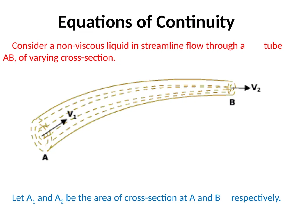
Consider a non-viscous liquid in streamline flow through a tube AB, of varying cross-section.
Let A1 and A2 be the area of cross-section at A and B respectively. Equations of Continuity<br>
Let A1 and A2 be the area of cross-section at A and B respectively. Equations of Continuity<br>
04
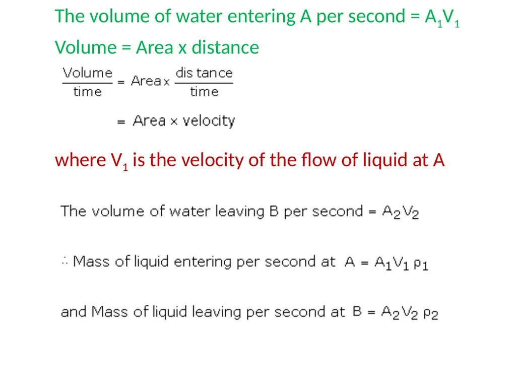
The volume of water entering A per second = A1V1
Volume = Area x distance
where V1 is the velocity of the flow of liquid at A<br>
Volume = Area x distance
where V1 is the velocity of the flow of liquid at A<br>
05
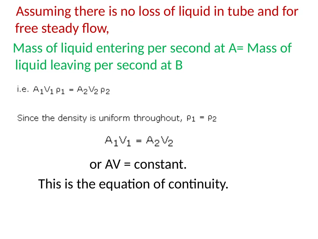
Assuming there is no loss of liquid in tube and for free steady flow,
Mass of liquid entering per second at A= Mass of liquid leaving per second at B
or AV = constant.
This is the equation of continuity.<br>
Mass of liquid entering per second at A= Mass of liquid leaving per second at B
or AV = constant.
This is the equation of continuity.<br>
06
Steam Nozzle Steam nozzle is an insulated passage of varying cross-sectional area through which heat energy (Enthalpy), pressure of steam is converted into kinetic energy.<br>
07
Steam Nozzle Functions of Nozzle :-
1) The main function of the steam nozzle is to convert heat energy to kinetic energy.
2) To direct the steam at high velocity into blades of turbine at required angle.
Applications :-
1) Steam & gas turbines are used to produces a high velocity jet.
2) Jet engines and rockets to produce thrust (propulsive force)<br>
1) The main function of the steam nozzle is to convert heat energy to kinetic energy.
2) To direct the steam at high velocity into blades of turbine at required angle.
Applications :-
1) Steam & gas turbines are used to produces a high velocity jet.
2) Jet engines and rockets to produce thrust (propulsive force)<br>
08
Types of nozzles 1) Convergent nozzle
2) divergent nozzle
3) convergent - divergent nozzle<br>
2) divergent nozzle
3) convergent - divergent nozzle<br>
09
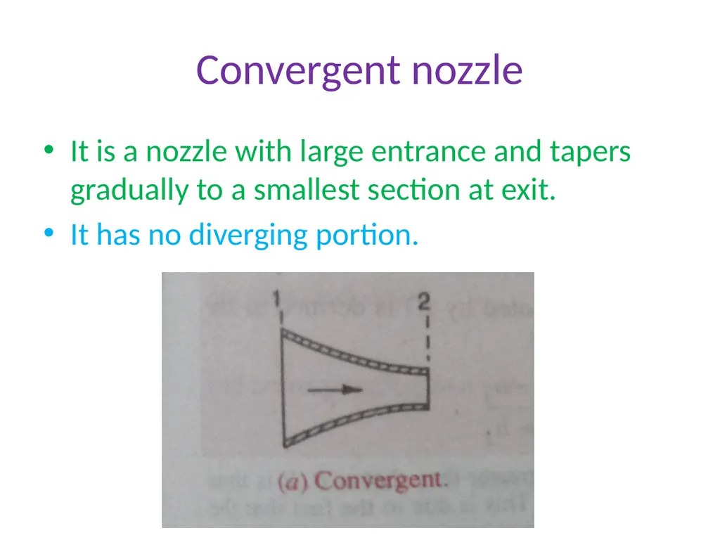
Convergent nozzle It is a nozzle with large entrance and tapers gradually to a smallest section at exit.
It has no diverging portion.<br>
It has no diverging portion.<br>
10
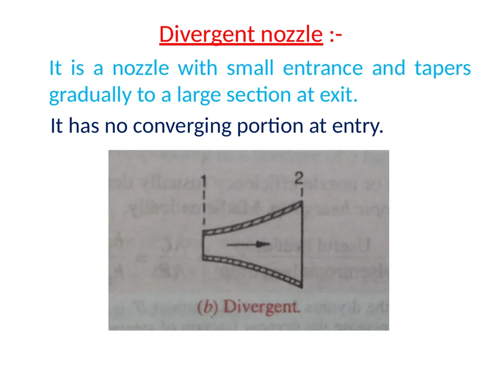
Divergent nozzle :- It is a nozzle with small entrance and tapers gradually to a large section at exit.
It has no converging portion at entry.<br>
It has no converging portion at entry.<br>
11
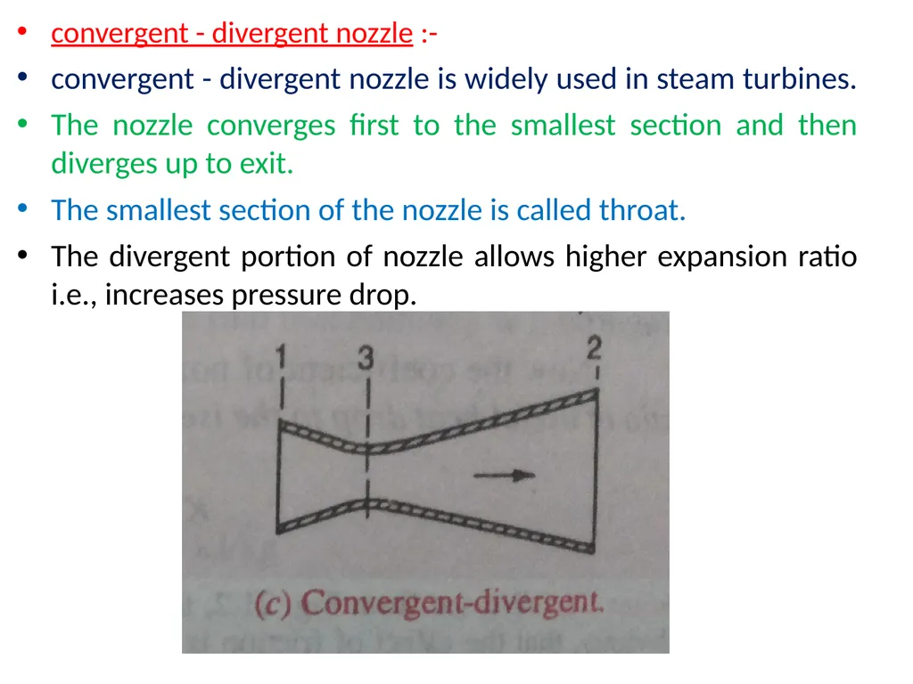
convergent - divergent nozzle :-
convergent - divergent nozzle is widely used in steam turbines.
The nozzle converges first to the smallest section and then diverges up to exit.
The smallest section of the nozzle is called throat.
The divergent portion of nozzle allows higher expansion ratio i.e., increases pressure drop.<br>
convergent - divergent nozzle is widely used in steam turbines.
The nozzle converges first to the smallest section and then diverges up to exit.
The smallest section of the nozzle is called throat.
The divergent portion of nozzle allows higher expansion ratio i.e., increases pressure drop.<br>
12
convergent - divergent nozzle : The taper of diverging sides of the nozzle ranges from 60 to 150 .
if the taper is above 150 turbulent is increased.
However if it is less than 60, the length of the nozzle will increases<br>
if the taper is above 150 turbulent is increased.
However if it is less than 60, the length of the nozzle will increases<br>
13
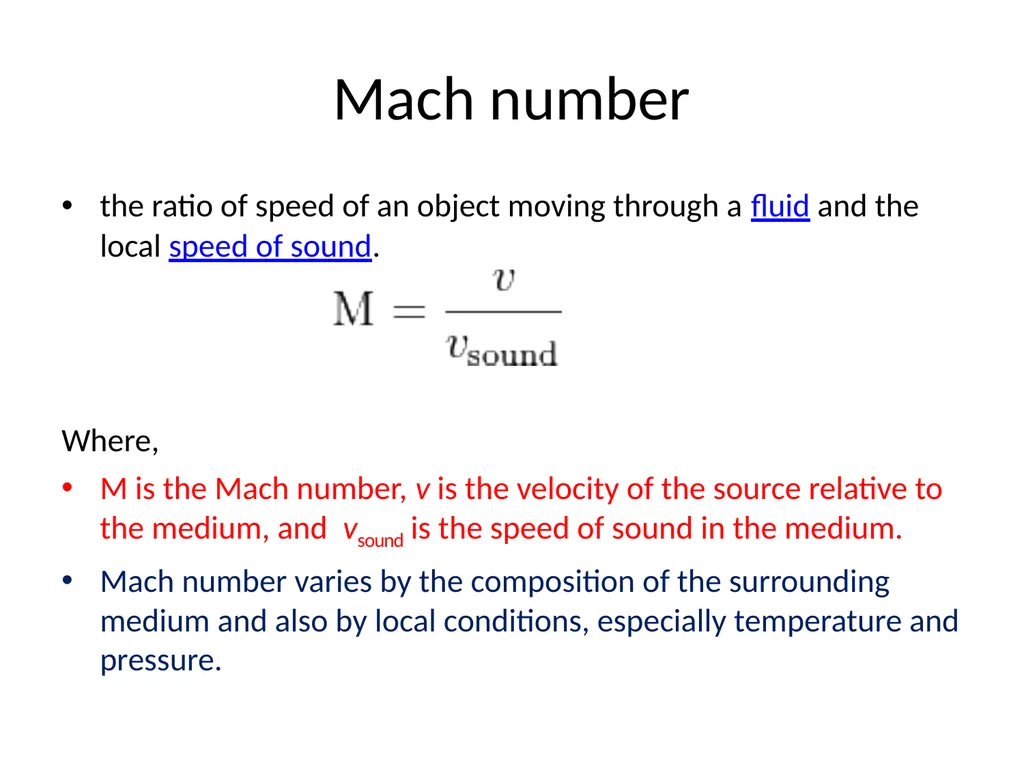
Mach number the ratio of speed of an object moving through a fluid and the local speed of sound.
Where,
M is the Mach number, v is the velocity of the source relative to the medium, and vsound is the speed of sound in the medium.
Mach number varies by the composition of the surrounding medium and also by local conditions, especially temperature and pressure.<br>
Where,
M is the Mach number, v is the velocity of the source relative to the medium, and vsound is the speed of sound in the medium.
Mach number varies by the composition of the surrounding medium and also by local conditions, especially temperature and pressure.<br>
14
Mach number M< 1 , the flow is called subsonic.
M=1, the flow is called sonic.
M>1, the flow is called supersonic.
M>5, the flow is called hypersonic.<br>
M=1, the flow is called sonic.
M>1, the flow is called supersonic.
M>5, the flow is called hypersonic.<br>
15
Steam turbine<br>
16
Classification of Steam Turbine : Classification of Steam Turbine :
Steam turbines are classified according to :
Principle of action of steam Method of governing
a. Impulse turbine a. Throttle
b. Reaction turbine b. Nozzle
Direction of steam flow c. By-pass
a. Axial d. Combination of throttle , nozzle
b. Radial by pass
c. Tangential
Number of pressure stages
a. Single stage
b. Multi stage<br>
Steam turbines are classified according to :
Principle of action of steam Method of governing
a. Impulse turbine a. Throttle
b. Reaction turbine b. Nozzle
Direction of steam flow c. By-pass
a. Axial d. Combination of throttle , nozzle
b. Radial by pass
c. Tangential
Number of pressure stages
a. Single stage
b. Multi stage<br>
17
Impulse turbine<br>
18
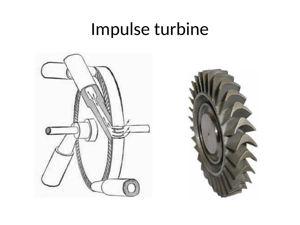
impulse turbine impulse turbine is a type of steam turbine where the rotor derives its rotational force from the impact force, or the direct push of steam on the blades.
The impulse turbine was first built in 1883 by the Swedish engineer De Laval.
The impulse turbine consists of a rotor mounted on a shaft that is free to rotate.
Attached to the rotor are a set of curved blades. Nozzles then direct the high pressure and high temperature steam towards the blades of the turbines.
The blades catch the impact force of the rapidly moving steam and rotate from this force.
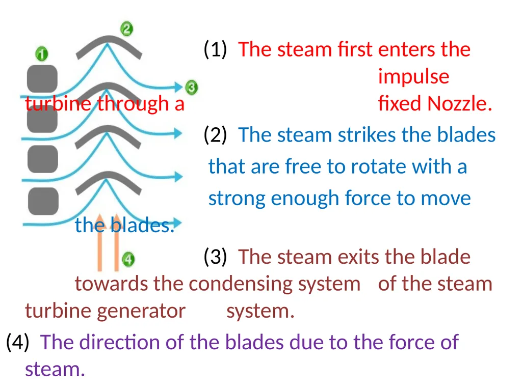
Below is a simple diagram of impulse turbine blades:<br>
The impulse turbine was first built in 1883 by the Swedish engineer De Laval.
The impulse turbine consists of a rotor mounted on a shaft that is free to rotate.
Attached to the rotor are a set of curved blades. Nozzles then direct the high pressure and high temperature steam towards the blades of the turbines.
The blades catch the impact force of the rapidly moving steam and rotate from this force.
Below is a simple diagram of impulse turbine blades:<br>
19
(1) The steam first enters the impulse turbine through a fixed Nozzle.
(2) The steam strikes the blades
that are free to rotate with a
strong enough force to move the blades.
(3) The steam exits the blade towards the condensing system of the steam turbine generator system.
(4) The direction of the blades due to the force of steam.<br>
(2) The steam strikes the blades
that are free to rotate with a
strong enough force to move the blades.
(3) The steam exits the blade towards the condensing system of the steam turbine generator system.
(4) The direction of the blades due to the force of steam.<br>
20
Reaction turbine A reaction turbine is a type of steam turbine that works on the principle that the rotor spins, as the name suggests, from a reaction force rather than an impact or impulse force.
In a reaction turbine there are no nozzles to direct the steam like in the impulse turbine.
Instead, the blades that project radially from the outer edge of the rotor are shaped and mounted so that the shape between the blades, created by the cross-section, create the shape of a nozzle. These blades are mounted on the revolving part of the rotor and are called the moving blades.<br>
In a reaction turbine there are no nozzles to direct the steam like in the impulse turbine.
Instead, the blades that project radially from the outer edge of the rotor are shaped and mounted so that the shape between the blades, created by the cross-section, create the shape of a nozzle. These blades are mounted on the revolving part of the rotor and are called the moving blades.<br>
21
Reaction turbine The fixed blades, which are the same shape as the moving blades, are mounted to the outer casing where the rotor revolves and are set to guide the steam into the moving blades.
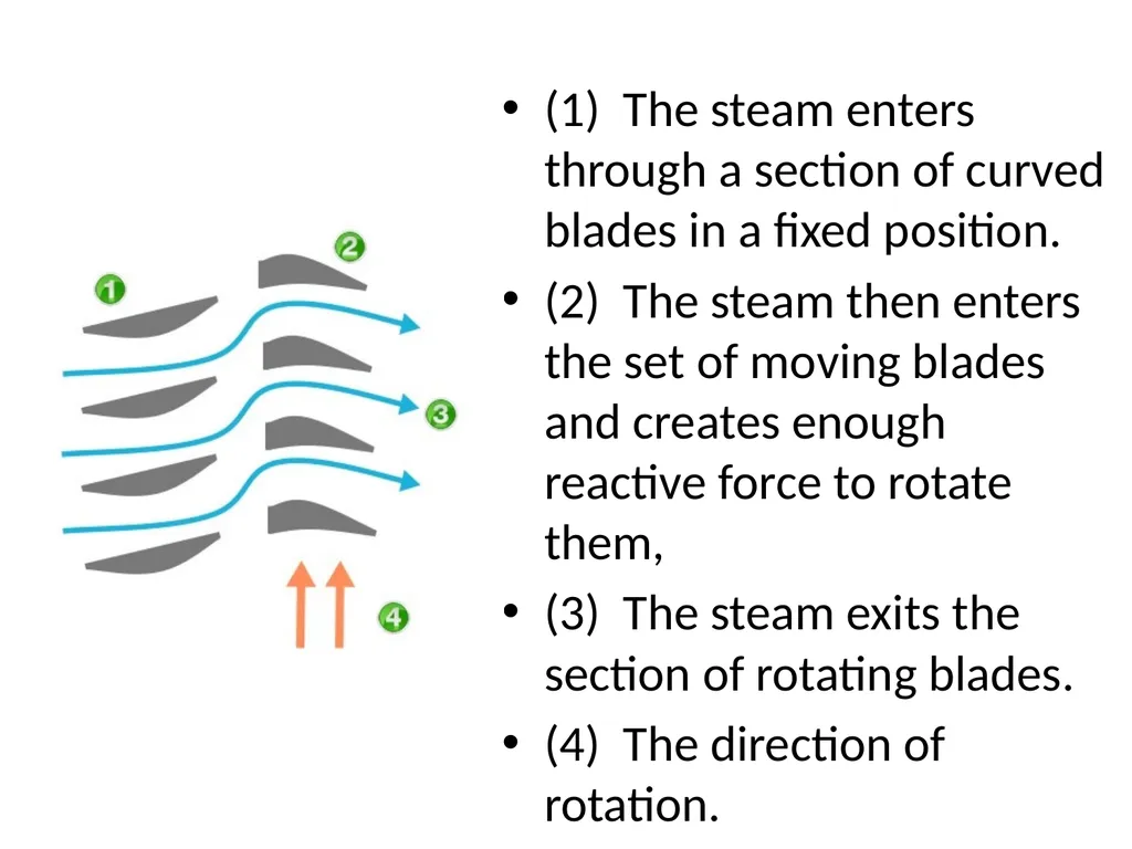
Below is a simple diagram of reaction turbine blades:<br>
Below is a simple diagram of reaction turbine blades:<br>
22
(1) The steam enters through a section of curved blades in a fixed position.
(2) The steam then enters the set of moving blades and creates enough reactive force to rotate them,
(3) The steam exits the section of rotating blades.
(4) The direction of rotation.<br>
(2) The steam then enters the set of moving blades and creates enough reactive force to rotate them,
(3) The steam exits the section of rotating blades.
(4) The direction of rotation.<br>
23
Reaction turbine There are three main forces that act to move a reaction turbine.
First, from the reactive force that is created on the moving blades as it expands and increases in velocity as it moves through the nozzle shaped spaces between the blades.
Second, from the reactive force produced on the moving blades as the steam passes through and changes directions.
Third, and to a lesser extent, from the impact force of the steam on the blades helps rotate the reaction turbine.<br>
First, from the reactive force that is created on the moving blades as it expands and increases in velocity as it moves through the nozzle shaped spaces between the blades.
Second, from the reactive force produced on the moving blades as the steam passes through and changes directions.
Third, and to a lesser extent, from the impact force of the steam on the blades helps rotate the reaction turbine.<br>
24
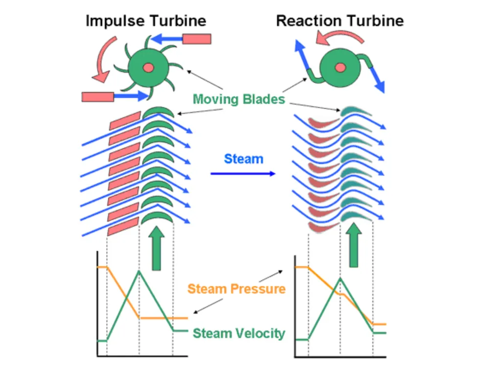
Difference between Impulse and Reaction Turbine In impulse turbine, there are nozzle and moving blades are in series while there are fixed blades and moving blades are present in Reaction turbine (No nozzle is present in reaction turbine).
In impulse turbine pressure falls in nozzle while in reaction turbine in fixed blade boiler pressure falls.
In impulse turbine velocity (or kinetic energy) of steam increases in nozzle while this work is to be done by fixed blades in the reaction turbine.
Compounding is to be done for impulse turbines to increase their efficiency while no compounding is necessary in reaction turbine.
In impulse turbine pressure drop per stage is more than reaction turbine.<br>
In impulse turbine pressure falls in nozzle while in reaction turbine in fixed blade boiler pressure falls.
In impulse turbine velocity (or kinetic energy) of steam increases in nozzle while this work is to be done by fixed blades in the reaction turbine.
Compounding is to be done for impulse turbines to increase their efficiency while no compounding is necessary in reaction turbine.
In impulse turbine pressure drop per stage is more than reaction turbine.<br>
25
Difference between Impulse and Reaction Turbine 6) Not much power can be developed in impulse turbine than reaction turbine.
7)Efficiency of impulse turbine is lower than reaction turbine.
8)Impulse turbine requires less space than reaction turbine.
9)Blade manufacturing of impulse turbine is not difficult as in reaction turbine it is difficult.<br>
7)Efficiency of impulse turbine is lower than reaction turbine.
8)Impulse turbine requires less space than reaction turbine.
9)Blade manufacturing of impulse turbine is not difficult as in reaction turbine it is difficult.<br>
26
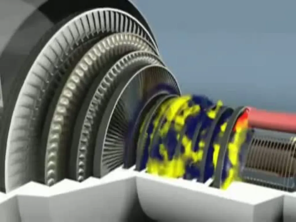
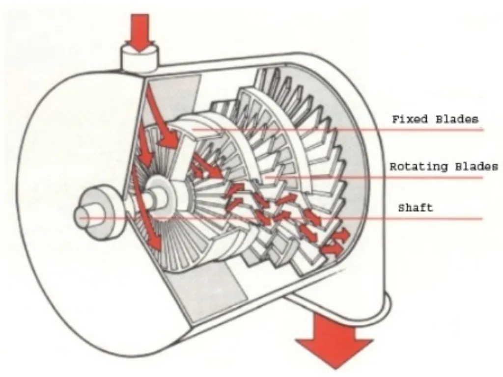
Compounding of steam turbines Compounding of steam turbines is the method in which energy from the steam is extracted in a number of stages rather than a single stage in a turbine.
A compounded steam turbine has multiple stages i.e. it has more than one set of nozzles and rotors, in series, keyed to the shaft or fixed to the casing, so that either the steam pressure or the jet velocity is absorbed by the turbine in number of stages.<br>
A compounded steam turbine has multiple stages i.e. it has more than one set of nozzles and rotors, in series, keyed to the shaft or fixed to the casing, so that either the steam pressure or the jet velocity is absorbed by the turbine in number of stages.<br>
27
Compounding of steam turbines As we have seen , if the high velocity steam is allowed to flow through one row of moving blades, it produces a rotor speed of about 30000 r.p.m. which is too high for practical use.
Not only this, the leaving loss is also very high.
It is therefore essential to incorporate some improvements in the simple impulse turbine for practical use and also to achieve high performance.
This is possible by making use of more than one set of nozzles, blades, rotors, in a series, keyed to a common shaft.<br>
Not only this, the leaving loss is also very high.
It is therefore essential to incorporate some improvements in the simple impulse turbine for practical use and also to achieve high performance.
This is possible by making use of more than one set of nozzles, blades, rotors, in a series, keyed to a common shaft.<br>
28
Compounding of steam turbines So that either the steam pressure or the jet velocity is absorbed by the turbine in stages.
The leaving loss also will be less.
This process is called compounding of steam turbine.<br>
The leaving loss also will be less.
This process is called compounding of steam turbine.<br>
29
Types of compounding In an Impulse steam turbine compounding can be achieved in the following three ways: -
1. Velocity compounding
2. Pressure compounding
3. Pressure-Velocity Compounding<br>
1. Velocity compounding
2. Pressure compounding
3. Pressure-Velocity Compounding<br>
30
velocity compounded The velocity compounded Impulse turbine was first proposed by C G Curtis to solve the problem of single stage Impulse turbine for use of high pressure and temperature steam.
The rings of moving blades are separated by rings of fixed blades. The moving blades are keyed to the turbine shaft and the fixed blades are fixed to the casing.
The high pressure steam coming from the boiler is expanded in the nozzle first. The Nozzle converts the pressure energy of the steam into kinetic energy
It is interesting to note that the total enthalpy drop and hence the pressure drop occurs in the nozzle. Hence, the pressure thereafter remains constant.
This high velocity steam is directed on to the first set (ring) of moving blades. As the steam flows over the blades, due the shape of the blades, it imparts some of its momentum to the blades and losses some velocity.<br>
The rings of moving blades are separated by rings of fixed blades. The moving blades are keyed to the turbine shaft and the fixed blades are fixed to the casing.
The high pressure steam coming from the boiler is expanded in the nozzle first. The Nozzle converts the pressure energy of the steam into kinetic energy
It is interesting to note that the total enthalpy drop and hence the pressure drop occurs in the nozzle. Hence, the pressure thereafter remains constant.
This high velocity steam is directed on to the first set (ring) of moving blades. As the steam flows over the blades, due the shape of the blades, it imparts some of its momentum to the blades and losses some velocity.<br>
31
velocity compounded Only a part of the high kinetic energy is absorbed by these blades. The remainder is exhausted on to the next ring of fixed blade.
The function of the fixed blades is to redirect the steam leaving from the first ring moving blades to the second ring of moving blades. There is no change in the velocity of the steam as it passes through the fixed blades.
The steam then enters the next ring of moving blades; this process is repeated until practically all the energy of the steam has been absorbed.
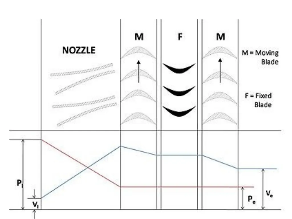
A schematic diagram of the Curtis stage impulse turbine, with two rings of moving blades one ring of fixed blades is shown in figure 1. The figure also shows the changes in the pressure and the absolute steam velocity as it passes through the stages.<br>
The function of the fixed blades is to redirect the steam leaving from the first ring moving blades to the second ring of moving blades. There is no change in the velocity of the steam as it passes through the fixed blades.
The steam then enters the next ring of moving blades; this process is repeated until practically all the energy of the steam has been absorbed.
A schematic diagram of the Curtis stage impulse turbine, with two rings of moving blades one ring of fixed blades is shown in figure 1. The figure also shows the changes in the pressure and the absolute steam velocity as it passes through the stages.<br>
32
velocity compounded where,
Pi = pressure of steam at inlet
Vi = velocity of steam at inlet
Po = pressure of steam at outlet
Vo = velocity of steam at outlet
In the above figure there are two rings of moving blades separated by a single of ring of fixed blades.
As discussed earlier the entire pressure drop occurs in the nozzle, and there are no subsequent pressure losses in any of the following stages. Velocity drop occurs in the moving blades and not in fixed blades.<br>
Pi = pressure of steam at inlet
Vi = velocity of steam at inlet
Po = pressure of steam at outlet
Vo = velocity of steam at outlet
In the above figure there are two rings of moving blades separated by a single of ring of fixed blades.
As discussed earlier the entire pressure drop occurs in the nozzle, and there are no subsequent pressure losses in any of the following stages. Velocity drop occurs in the moving blades and not in fixed blades.<br>
33
advantages Velocity compounded impulse turbine requires a comparatively small number of stages due to relatively large heat drop per stage.
Due to small number of stages the initial cost is less.
In two or three row wheel, the steam temperature is sufficiently lo, hence a cast iron cylinder may be used , thus saving material cost.<br>
Due to small number of stages the initial cost is less.
In two or three row wheel, the steam temperature is sufficiently lo, hence a cast iron cylinder may be used , thus saving material cost.<br>
34
disadvantages The velocity compounded impulse turbine has low efficiency and high steam consumption.<br>
35
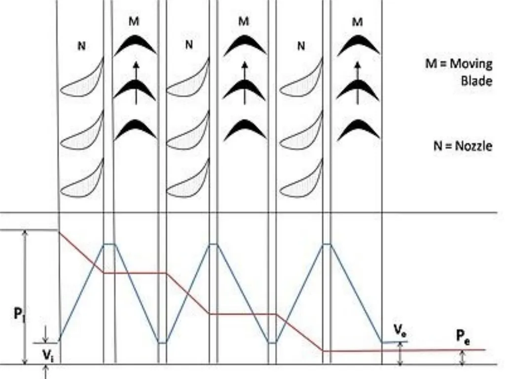
pressure compounded The pressure compounded Impulse turbine is also called as Rateau turbine, after its inventor. This is used to solve the problem of high blade velocity in the single-stage impulse turbine.
It consists of alternate rings of nozzles and turbine blades. The nozzles are fitted to the casing and the blades are keyed to the turbine shaft.
In this type of compounding the steam is expanded in a number of stages, instead of just one (nozzle) in the velocity compounding.
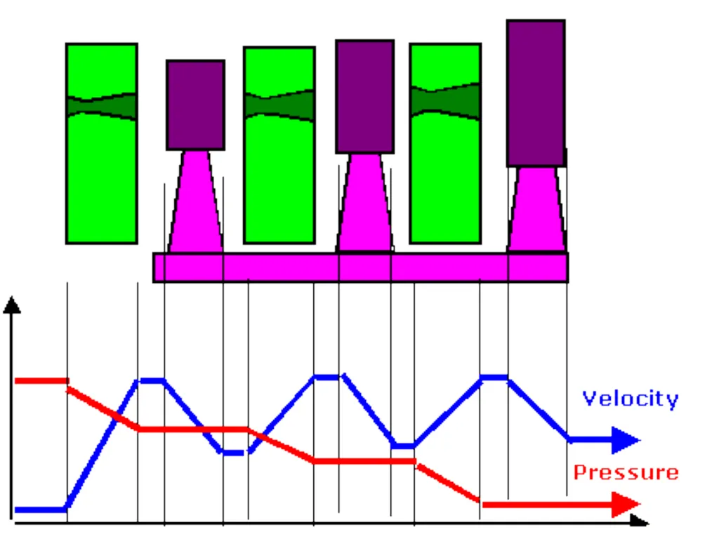
It is done by the fixed blades which act as nozzles. The steam expands equally in all rows of fixed blade. The steam coming from the boiler is fed to the first set of fixed blades i.e. the nozzle ring. The steam is partially expanded in the nozzle ring.
Hence, there is a partial decrease in pressure of the incoming steam. This leads to an increase in the velocity of the steam. Therefore the pressure decreases and velocity increases partially in the nozzle.<br>
It consists of alternate rings of nozzles and turbine blades. The nozzles are fitted to the casing and the blades are keyed to the turbine shaft.
In this type of compounding the steam is expanded in a number of stages, instead of just one (nozzle) in the velocity compounding.
It is done by the fixed blades which act as nozzles. The steam expands equally in all rows of fixed blade. The steam coming from the boiler is fed to the first set of fixed blades i.e. the nozzle ring. The steam is partially expanded in the nozzle ring.
Hence, there is a partial decrease in pressure of the incoming steam. This leads to an increase in the velocity of the steam. Therefore the pressure decreases and velocity increases partially in the nozzle.<br>
36
pressure compounded This is then passed over the set of moving blades. As the steam flows over the moving blades nearly all its velocity is absorbed. However, the pressure remains constant during this process.
After this it is passed into the nozzle ring and is again partially expanded. Then it is fed into the next set of moving blades, and this process is repeated until the condenser pressure is reached.
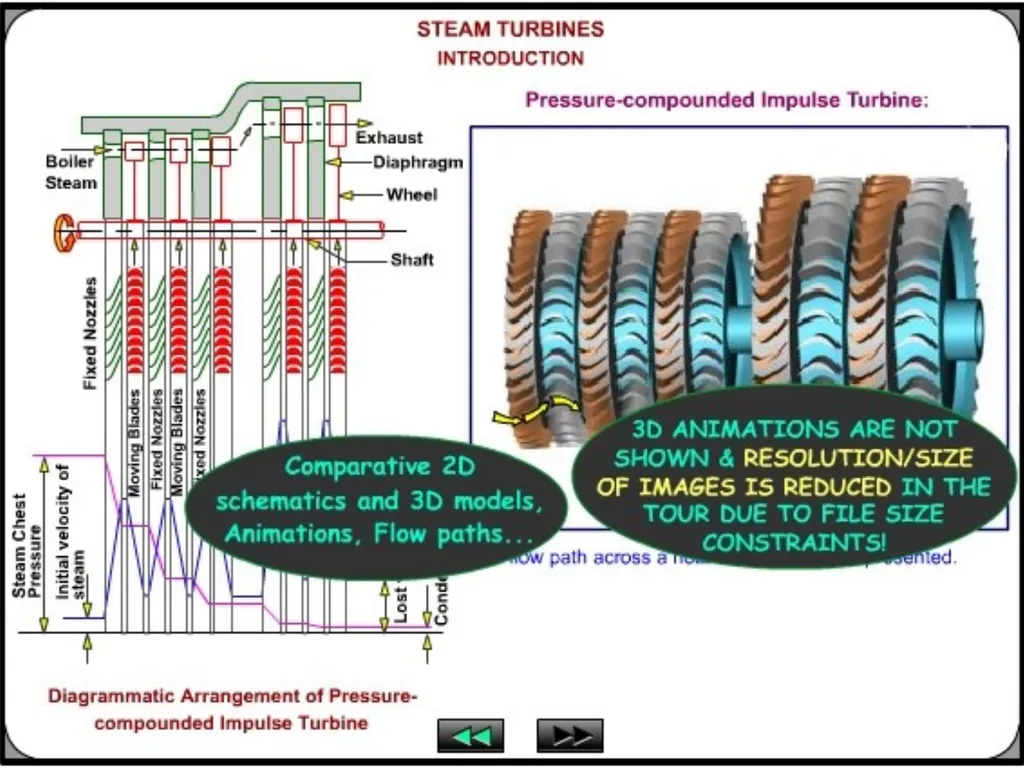
This process has been illustrated in figure 3.
where, the symbols have the same meaning as given above.
It is a three stage pressure compounded impulse turbine. Each stage consists of one ring of fixed blades, which act as nozzles, and one ring of moving blades. As shown in the figure pressure drop takes place in the nozzles and is distributed in many stages.<br>
After this it is passed into the nozzle ring and is again partially expanded. Then it is fed into the next set of moving blades, and this process is repeated until the condenser pressure is reached.
This process has been illustrated in figure 3.
where, the symbols have the same meaning as given above.
It is a three stage pressure compounded impulse turbine. Each stage consists of one ring of fixed blades, which act as nozzles, and one ring of moving blades. As shown in the figure pressure drop takes place in the nozzles and is distributed in many stages.<br>
37
Disadvantages of Pressure Compounding The disadvantage is that since there is pressure drop in the nozzles, it has to be made air-tight.
They are bigger and bulkier in size<br>
They are bigger and bulkier in size<br>
38
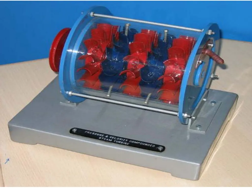
Pressure-Velocity compounded Impulse Turbine It is a combination of the above two types of compounding. The total pressure drop of the steam is divided into a number of stages.
Each stage consists of rings of fixed and moving blades. Each set of rings of moving blades is separated by a single ring of fixed blades.
In each stage there is one ring of fixed blades and 3-4 rings of moving blades. Each stage acts as a velocity compounded impulse turbine.
The fixed blades act as nozzles. The steam coming from the boiler is passed to the first ring of fixed blades, where it gets partially expanded.<br>
Each stage consists of rings of fixed and moving blades. Each set of rings of moving blades is separated by a single ring of fixed blades.
In each stage there is one ring of fixed blades and 3-4 rings of moving blades. Each stage acts as a velocity compounded impulse turbine.
The fixed blades act as nozzles. The steam coming from the boiler is passed to the first ring of fixed blades, where it gets partially expanded.<br>
39
Pressure-Velocity compounded Impulse Turbine The pressure partially decreases and the velocity rises correspondingly. The velocity is absorbed by the following rings of moving blades until it reaches the next ring of fixed blades and the whole process is repeated once again.
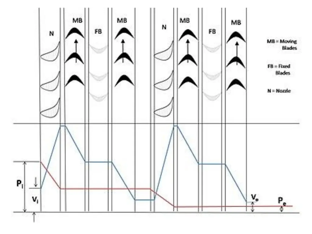
This process is shown diagrammatically in figure 5.
where, symbols have their usual meaning.<br>
This process is shown diagrammatically in figure 5.
where, symbols have their usual meaning.<br>
40
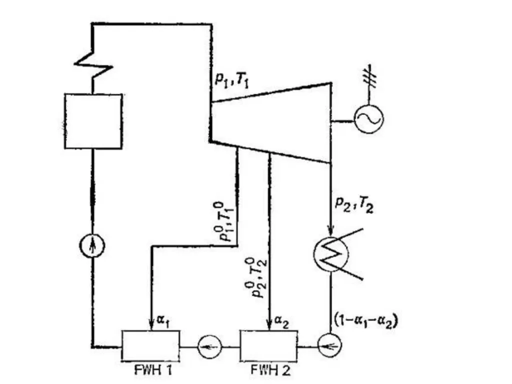
Regenerative feed heating The dry saturated steam , from boiler, enters the turbine at a high temperature, and then expands isentropically to a lower temperature in the same way as that of Rankine and Carnot cycle.
Now the condensate from condenser, is pumped back and circulated around the turbine casing.
The direction opposite to the steam flow in the turbine.
The steam is thus heated before entering in to the boiler, such a system of heating is known as regenerative heating.<br>
Now the condensate from condenser, is pumped back and circulated around the turbine casing.
The direction opposite to the steam flow in the turbine.
The steam is thus heated before entering in to the boiler, such a system of heating is known as regenerative heating.<br>
41
Regenerative feed heating<br>
42
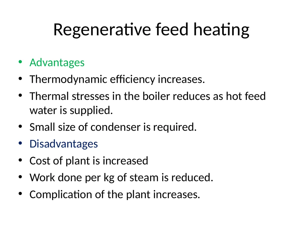
Regenerative feed heating Advantages
Thermodynamic efficiency increases.
Thermal stresses in the boiler reduces as hot feed water is supplied.
Small size of condenser is required.
Disadvantages
Cost of plant is increased
Work done per kg of steam is reduced.
Complication of the plant increases.<br>
Thermodynamic efficiency increases.
Thermal stresses in the boiler reduces as hot feed water is supplied.
Small size of condenser is required.
Disadvantages
Cost of plant is increased
Work done per kg of steam is reduced.
Complication of the plant increases.<br>
43
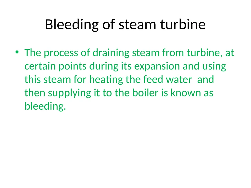
Bleeding of steam turbine The process of draining steam from turbine, at certain points during its expansion and using this steam for heating the feed water and then supplying it to the boiler is known as bleeding.<br>
44
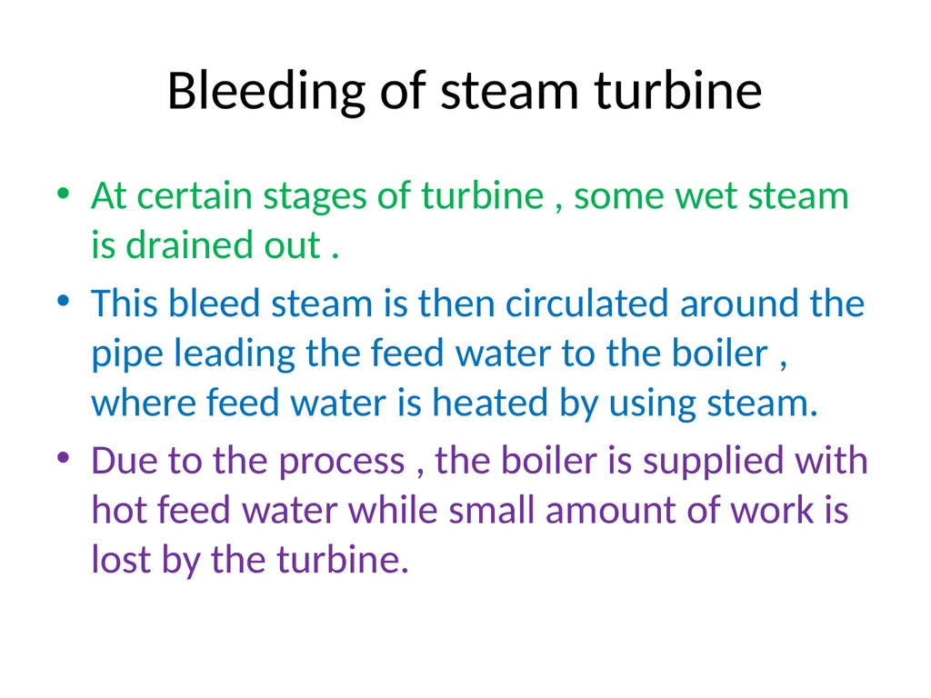
Bleeding of steam turbine At certain stages of turbine , some wet steam is drained out .
This bleed steam is then circulated around the pipe leading the feed water to the boiler , where feed water is heated by using steam.
Due to the process , the boiler is supplied with hot feed water while small amount of work is lost by the turbine.<br>
This bleed steam is then circulated around the pipe leading the feed water to the boiler , where feed water is heated by using steam.
Due to the process , the boiler is supplied with hot feed water while small amount of work is lost by the turbine.<br>
45
Governing Steam turbine governing is the procedure of controlling the flow rate of steam into a steam turbine so as to maintain its speed of rotation as constant.
The variation in load during the operation of a steam turbine can have a significant impact on its performance.
In a practical situation the load frequently varies from the designed or economic load and thus there always exists a considerable deviation from the desired performance of the turbine.
The primary objective in the steam turbine operation is to maintain a constant speed of rotation irrespective of the varying load. This can be achieved by means of governing in a steam turbine.<br>
The variation in load during the operation of a steam turbine can have a significant impact on its performance.
In a practical situation the load frequently varies from the designed or economic load and thus there always exists a considerable deviation from the desired performance of the turbine.
The primary objective in the steam turbine operation is to maintain a constant speed of rotation irrespective of the varying load. This can be achieved by means of governing in a steam turbine.<br>
46
Throttle governing In throttle governing the pressure of steam is reduced at the turbine entry thereby decreasing the availability of energy.
In this method steam is allowed to pass through a restricted passage thereby reducing its pressure across the governing valve.[
The flow rate is controlled using a partially opened steam control valve. The reduction in pressure leads to a throttling process in which the enthalpy of steam remains constant,
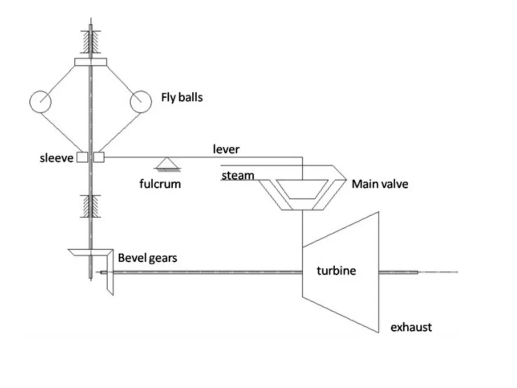
Low initial cost and simple mechanism makes throttle governing the most apt method for small steam turbines. The mechanism is illustrated in figure 1.
The valve is actuated by using a centrifugal governor which consists of flying balls attached to the arm of the sleeve.<br>
In this method steam is allowed to pass through a restricted passage thereby reducing its pressure across the governing valve.[
The flow rate is controlled using a partially opened steam control valve. The reduction in pressure leads to a throttling process in which the enthalpy of steam remains constant,
Low initial cost and simple mechanism makes throttle governing the most apt method for small steam turbines. The mechanism is illustrated in figure 1.
The valve is actuated by using a centrifugal governor which consists of flying balls attached to the arm of the sleeve.<br>
47
Throttle governing A geared mechanism connects the turbine shaft to the rotating shaft on which the sleeve reciprocates axially.
With a reduction in the load the turbine shaft speed increases and brings about the movement of the flying balls away from the sleeve axis.
This result in an axial movement of the sleeve followed by the activation of a lever, which in turn actuates the main stop valve to a partially opened position to control the flow rate.<br>
With a reduction in the load the turbine shaft speed increases and brings about the movement of the flying balls away from the sleeve axis.
This result in an axial movement of the sleeve followed by the activation of a lever, which in turn actuates the main stop valve to a partially opened position to control the flow rate.<br>
48
Nozzle governing In nozzle governing the flow rate of steam is regulated by opening and shutting of sets of nozzles rather than regulating its pressure.
In this method groups of two, three or more nozzles form a set and each set is controlled by a separate valve.
The actuation of individual valve closes the corresponding set of nozzle thereby controlling the flow rate.
In actual turbine, nozzle governing is applied only to the first stage whereas the subsequent stages remain unaffected. Since no regulation to the pressure is applied.
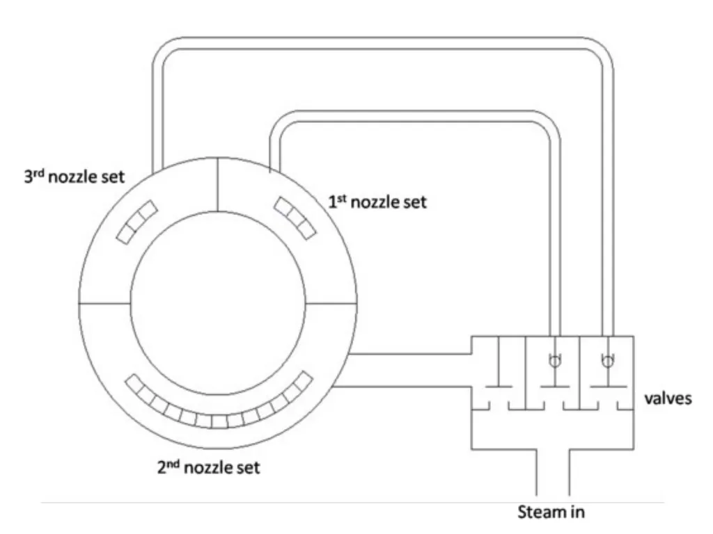
Figure 2 shows the mechanism of nozzle governing applied to steam turbines. As shown in the figure the three sets of nozzles are controlled by means of three separate valves.<br>
In this method groups of two, three or more nozzles form a set and each set is controlled by a separate valve.
The actuation of individual valve closes the corresponding set of nozzle thereby controlling the flow rate.
In actual turbine, nozzle governing is applied only to the first stage whereas the subsequent stages remain unaffected. Since no regulation to the pressure is applied.
Figure 2 shows the mechanism of nozzle governing applied to steam turbines. As shown in the figure the three sets of nozzles are controlled by means of three separate valves.<br>
49
By pass governing Occasionally the turbine is overloaded for short durations.
During such operation, bypass valves are opened and fresh steam is introduced into the later stages of the turbine.
This generates more energy to satisfy the increased load.
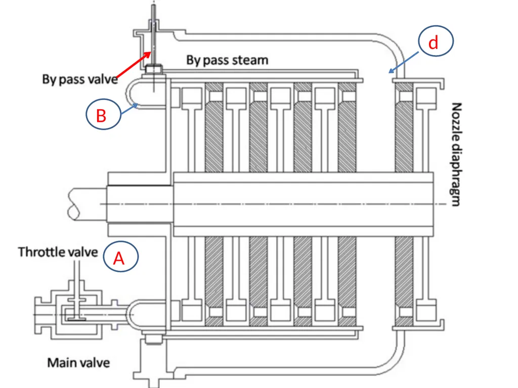
The schematic of bypass governing is as shown in figure3.<br>
During such operation, bypass valves are opened and fresh steam is introduced into the later stages of the turbine.
This generates more energy to satisfy the increased load.
The schematic of bypass governing is as shown in figure3.<br>
50
A B d<br>
51
By pass governing The total amount of steam entering the turbine passes through the valve A which is under the control of speed governor.
B is a nozzle box or steam chest .
For all loads greater than the economic load , a by pass valve c is opened, allowing steam to pass from the first stage nozzle box in to the steam belt D and so in to the nozzle of downstream stage.
The valve c is designed such that it is not opened until the lift of the valve a diminishes.
The by pass valve c remains under control of a speed governor for all loads within its range.<br>
B is a nozzle box or steam chest .
For all loads greater than the economic load , a by pass valve c is opened, allowing steam to pass from the first stage nozzle box in to the steam belt D and so in to the nozzle of downstream stage.
The valve c is designed such that it is not opened until the lift of the valve a diminishes.
The by pass valve c remains under control of a speed governor for all loads within its range.<br>
52
Losses in turbine Nozzle loss
It is important loss in impulse turbine , which occurs when the steam flows through the nozzle.
This loss takes place due to friction in the nozzle.
2) Blade friction loss
It is important loss in both the impulse and reaction turbines, which occurs hen steam glides over the blades.
This loss takes place due to friction of surface of blades.
As a result of blade friction, the relative velocity of steam is reduced while gliding over the blade.<br>
It is important loss in impulse turbine , which occurs when the steam flows through the nozzle.
This loss takes place due to friction in the nozzle.
2) Blade friction loss
It is important loss in both the impulse and reaction turbines, which occurs hen steam glides over the blades.
This loss takes place due to friction of surface of blades.
As a result of blade friction, the relative velocity of steam is reduced while gliding over the blade.<br>
53
Losses in turbine 3) wheel friction loss
It occurs when the turbine wheel rotates in steam.
This loss takes place due to resistance offered by the steam to the moving turbine wheel or disc.
As a result of this loss, the turbine wheel rotates at a lower speed.<br>
It occurs when the turbine wheel rotates in steam.
This loss takes place due to resistance offered by the steam to the moving turbine wheel or disc.
As a result of this loss, the turbine wheel rotates at a lower speed.<br>
54
Losses in turbine 4) Mechanical friction loss
It is loss in both turbine, which occurs due to friction between the shaft and wheel bearing as well as regulating the valves.
This loss can be reduced by lubricating the moving parts of turbine.
5) Leakage loss
It is loss in both turbines, which occurs due to leakage of steam at each stage to the turbine, blade tips.<br>
It is loss in both turbine, which occurs due to friction between the shaft and wheel bearing as well as regulating the valves.
This loss can be reduced by lubricating the moving parts of turbine.
5) Leakage loss
It is loss in both turbines, which occurs due to leakage of steam at each stage to the turbine, blade tips.<br>
55
Losses in turbine 6) Moisture loss
It is loss in both the turbines, which takes place due to moisture present in the steam.
This loss occurs when the steam, passing through lower stages, becomes wet.
The velocity of water particles is less than steam.
As a result of this , the steam has to drag the water particles, which reduces the kinetic energy of the steam.<br>
It is loss in both the turbines, which takes place due to moisture present in the steam.
This loss occurs when the steam, passing through lower stages, becomes wet.
The velocity of water particles is less than steam.
As a result of this , the steam has to drag the water particles, which reduces the kinetic energy of the steam.<br>
56
Losses in turbine 7) Radiation losses
It is a loss in both the turbines, which takes place due to difference of the temperature between the turbine casing and the surrounding atmosphere.
This is reduces by properly insulating the turbine.
8) Governing loss
It is loss in both the turbines, which occurs due to throttling of the steam at main stop valve of the governor.<br>
It is a loss in both the turbines, which takes place due to difference of the temperature between the turbine casing and the surrounding atmosphere.
This is reduces by properly insulating the turbine.
8) Governing loss
It is loss in both the turbines, which occurs due to throttling of the steam at main stop valve of the governor.<br>