Components of Ore Microscope Akhil Kumar Dwivedi Assistant Professor (Geology) Mohanlal Sukhadia University, Udaipur The Ore Microscope The basic instrument for petrographic examination of ore minerals or opaque minerals is the ore
"Components of Ore Microscope Akhil Kumar Dwivedi" is the property of its rightful owner. Permission is granted to
download and print the materials on this website for personal, non-commercial use only, and to display it
on your personal computer provided you do not modify the materials and that you retain all copyright
notices contained in the materials. By downloading content from our website, you accept the terms of this
agreement.
Presentation Transcript
01
Components of Ore Microscope Akhil Kumar Dwivedi
Assistant Professor (Geology)
Mohanlal Sukhadia University, Udaipur<br>
02
The Ore Microscope The basic instrument for petrographic examination of “ore” minerals or “opaque” minerals is the ore microscope, which is similar to a conventional petrographic microscope in the system of lenses, polarizer, analyzer and various diaphragms.
An ore microscope however, differs from a petrographic one in that it has an incident light source rather than a substage transmitting one, which allows examination of polished surfaces of opaque minerals under reflected light<br>
03
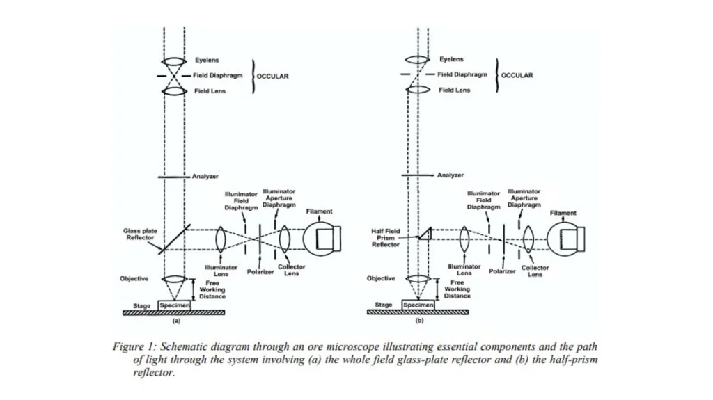
Components of the Ore Microscope Though there are numerous models of ore microscopes, there are certain basic elements common to all. These are:
The frame or stand which carries the other components.
A circular stage, graduated in degrees, that can be rotated through 360º , attached to the frame. This is usually equipped with a rack-and-pinion movement permitting it to be moved up and down for focusing the specimen, and sometimes a mechanical stage equipped with X and Y movement for systematic examination and point counting of grains in the specimen.
Objective lenses which are interchangeable and may be classed in terms of type (achromat, apochromat or fluorite). Their magnification, numerical aperture, and whether they are for oil immersion or air usage is indicated.
The occular serves to enlarge the primary image formed by the objective and render it visible to the eye. Occulars commonly contain cross hairs, a micrometer or a grid with a fixed rectangular pattern used for measuring particle sizes.<br>
04
Components of the Ore Microscope 5. The standard illuminating system consists of two lenses, two or three diaphragms, a polarizer and an incandescent lamp of 6-12 V and 15-100 W, or an LED. The illuminator aperture diaphragm restricts the field of view and stray scattered light. The illuminator field diaphragm controls the angle of the cone of light incident on the specimen and should be set to just enclose the field of view (this restricts the light to the most parallel rays, minimizes elliptical polarization and maximizes contrast). In many microscopes a third diaphragm helps sharpen the image.
6. The reflector is a means by which light is brought vertically onto the polished surface. Reflectors are of two types: the glass plate reflector (a partial mirror) and the half-field prism (see figure 1). Both types have their advantages and disadvantages. Many microscopes have both types mounted on a horizontal slide so that either may be used.
7. The polarizer is usually positioned within the illuminating system between the lamp and the collector lens but may also be located between the diaphragms. It is usually a calcite prism or a polaroid plate that renders light linearly polarized in a N-S orientation. The analyzer is a device similar to a polarizer but is positioned between the objective and occular with its vibration directions perpendicular to those of the polarizer.<br>
05
Accessories of the Ore Microscope: Monochromators: The visible range of light lies between 400 to 700 nm, whereas the operable range of most microscopes extends several hundred nm above and below this range. Since the optical properties of minerals vary as a function of wavelength, it is sometimes necessary to provide light of a particular wavelength. This is commonly achieved by the use of:
a) Fixed monochromatic interference filters which consist of a glass plate on which alternating layers of low reflecting transparent diaelectric substances and higher reflecting semitransparent metal films or diaelectrics of high R.I. are deposited. Light passing through these filters is not truly monochromatic but lies within a narrow band, usually less than 15 nm.
b) Continuous-spectrum monochromators are interference filters for which the wavelength of transmitted light varies continuously along the filter. A window, the width of which may be varied to control the passband width, may be slid along the monochromator to whatever wavelength is desired, thus providing monochromatic light over the entire visible range and even beyond.
Photometers: These are used to measure the reflectance of minerals. Most of them consist of a photomultiplier tube that has a high sensitivity throughout the visible spectrum. Photometers must be used in conjunction with stabilized light sources, high quality monochromators, and reflectance standards.<br>
06
Adjustment of the Microscope : For accurate observation of optical properties, a proper adjustment of various elements of the microscope is extremely important. Although most adjustments are done at the factory, certain others must be made by the ore microscopist.
1. Place a polished section on the stage and centre the objective / stage properly.
2. Replace the occular with a pinhole eyepiece and close down the aperture diaphragm until its image is a small circle of light. Rotate the reflector until the image of the aperture diaphragm is at the centre of the field.
3. Rotate the stage. If the image does not move, the polished section is level. If the image moves, the section should be leveled before proceeding.<br>
07
Adjustment of the Microscope : 4. Centre the light source. Attach a low power objective to the microscope, throw out the analyzer and remove the occular. The field of view should be evenly and brilliantly illuminated.
If peripheral shadows appear, the light source is off centre and must be adjusted by means of the centring screws.
5. Check the orientation of the axis of the reflecting device. Focus with a low power objective on a leveled polished surface.
Close down the iris diaphragm until brilliant illumination of the field is restricted to the smallest possible bright spot. Now rotate the reflector on its axis.
The bright spot should move across the field in a path precisely parallel to the N-S cross-hair of the occular. If the path is at an angle, the axis of the reflector is not horizontal and needs correction.<br>