
Computer Networking: A Top-Down Approach 9th

Description: Computer Networking: A Top-Down Approach 9th edition Jim Kurose, Keith Ross Pearson, 2025 Chapter 5 Network Layer: Control Plane A note on the use of these PowerPoint slides: Were making these slides freely available to all (faculty,
Related Topics
Download Presentation
"Computer Networking: A Top-Down Approach 9th" is the property of its rightful owner. Permission is granted to download and print the materials on this website for personal, non-commercial use only, and to display it on your personal computer provided you do not modify the materials and that you retain all copyright notices contained in the materials. By downloading content from our website, you accept the terms of this agreement.
Presentation Transcript
slide1. Computer Networking: A Top-Down Approach
9th edition
Jim Kurose, Keith Ross
Pearson, 2025 Chapter 5
Network Layer:
Control Plane A note on the use of these PowerPoint slides:
We’re making these slides freely available to all (faculty, students, readers). They’re in PowerPoint form so you see the animations; and can add, modify, and delete slides (including this one) and slide content to suit your needs. They obviously represent a lot of work on our part. In return for use, we only ask the following: If you use these slides (e.g., in a class) that you mention their source (after all, we’d like people to use our book!)
If you post any slides on a www site, that you note that they are adapted from (or perhaps identical to) our slides, and note our copyright of this material.
For a revision history, see the slide note for this page.
Thanks and enjoy! JFK/KWR
All material copyright 1996-2025
J.F Kurose and K.W. Ross, All Rights Reserved<br>
slide2. Network layer control plane: our goals understand principles behind network control plane:
traditional routing algorithms
SDN controllers
network management, configuration instantiation, implementation in the Internet:
OSPF, BGP
OpenFlow, ODL and ONOS controllers
Internet Control Message Protocol: ICMP
SNMP, YANG/NETCONF Network Layer: 5-2<br>
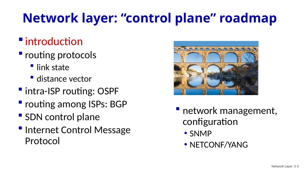
slide3. Network layer: “control plane” roadmap network management, configuration
SNMP
NETCONF/YANG introduction
routing protocols
link state
distance vector
intra-ISP routing: OSPF
routing among ISPs: BGP
SDN control plane
Internet Control Message Protocol Network Layer: 5-3<br>
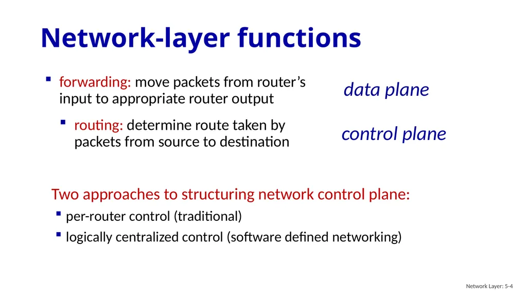
slide4. Two approaches to structuring network control plane:
per-router control (traditional)
logically centralized control (software defined networking) Network-layer functions Network Layer: 5-4<br>
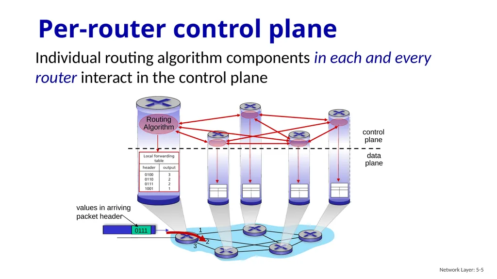
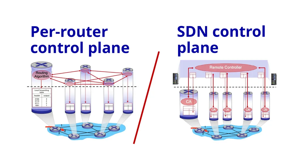
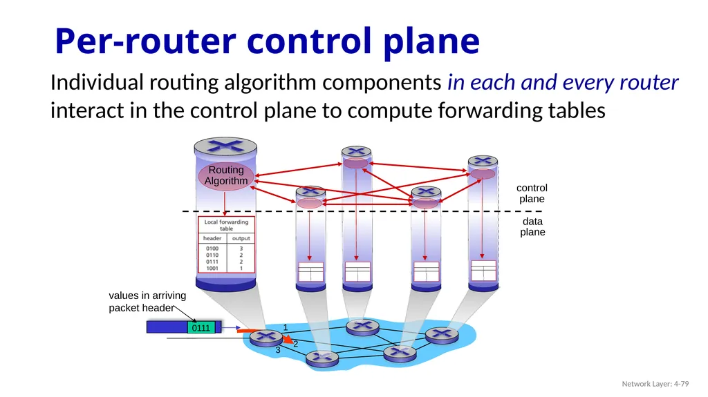
slide5. Per-router control plane Individual routing algorithm components in each and every router interact in the control plane 1 2 values in arriving
packet header 3 Network Layer: 5-5<br>
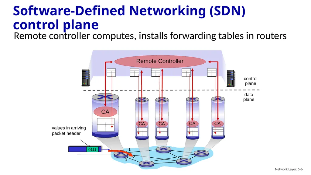
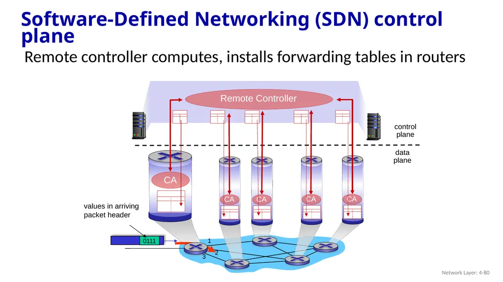
slide6. Software-Defined Networking (SDN) control plane Remote controller computes, installs forwarding tables in routers values in arriving
packet header Network Layer: 5-6<br>
slide7. Per-router control plane SDN control plane<br>
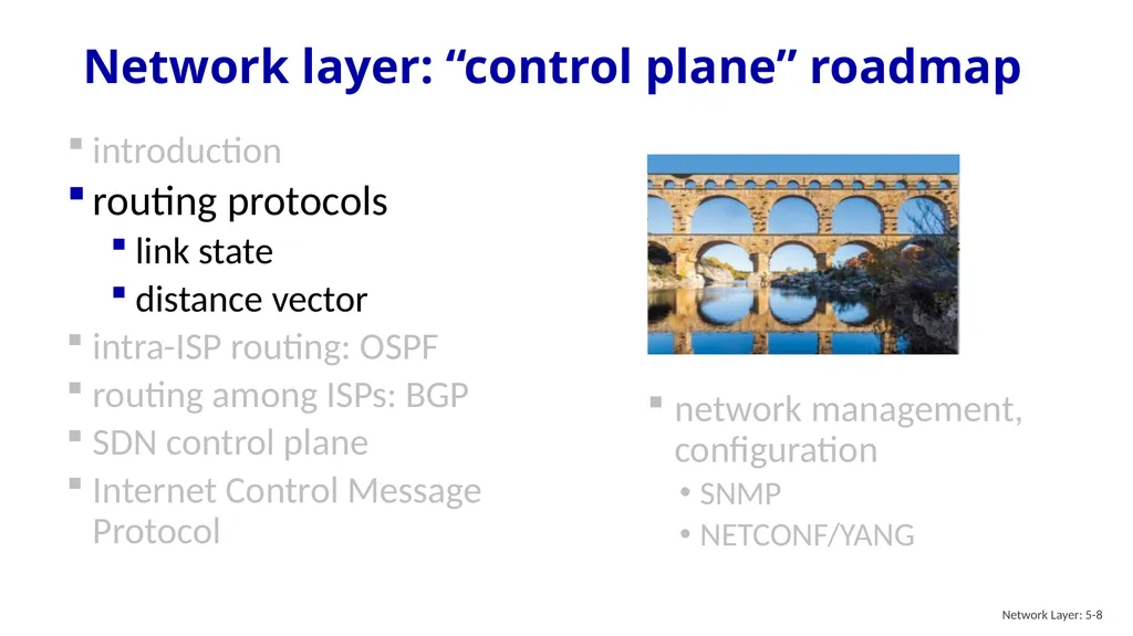
slide8. Network layer: “control plane” roadmap network management, configuration
SNMP
NETCONF/YANG introduction
routing protocols
link state
distance vector
intra-ISP routing: OSPF
routing among ISPs: BGP
SDN control plane
Internet Control Message Protocol Network Layer: 5-8<br>
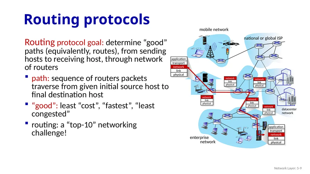
slide9. Routing protocol goal: determine “good” paths (equivalently, routes), from sending hosts to receiving host, through network of routers
path: sequence of routers packets traverse from given initial source host to final destination host
“good”: least “cost”, “fastest”, “least congested”
routing: a “top-10” networking challenge! Routing protocols mobile network enterprise
network national or global ISP datacenter
network Network Layer: 5-9<br>
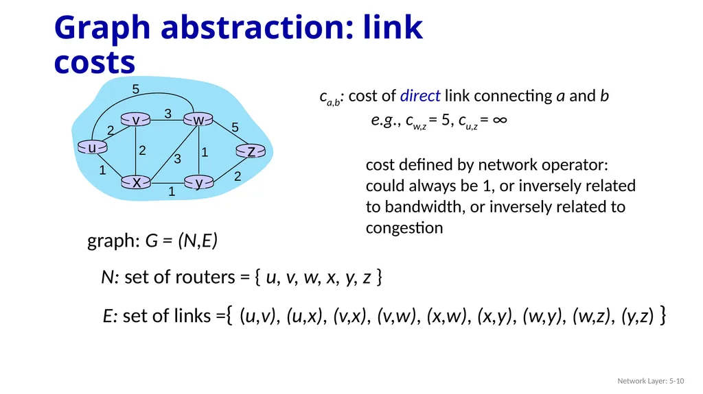
slide10. Graph abstraction: link costs Network Layer: 5-10 graph: G = (N,E) ca,b: cost of direct link connecting a and b
e.g., cw,z = 5, cu,z = ∞
cost defined by network operator: could always be 1, or inversely related to bandwidth, or inversely related to congestion N: set of routers = { u, v, w, x, y, z } E: set of links ={ (u,v), (u,x), (v,x), (v,w), (x,w), (x,y), (w,y), (w,z), (y,z) }<br>
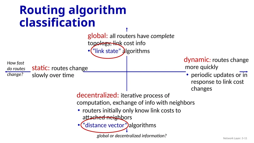
slide11. Routing algorithm classification Network Layer: 5-11 global or decentralized information? How fast do routes change?<br>
slide12. Network layer: “control plane” roadmap network management, configuration
SNMP
NETCONF/YANG introduction
routing protocols
link state
distance vector
intra-ISP routing: OSPF
routing among ISPs: BGP
SDN control plane
Internet Control Message Protocol Network Layer: 5-12<br>
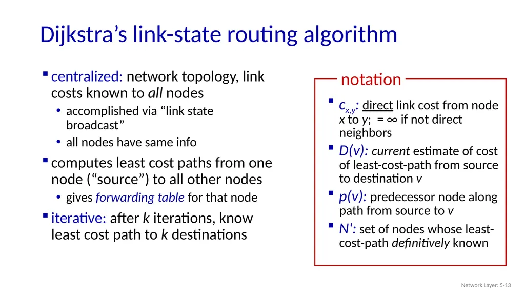
slide13. Dijkstra’s link-state routing algorithm Network Layer: 5-13 centralized: network topology, link costs known to all nodes
accomplished via “link state broadcast”
all nodes have same info
computes least cost paths from one node (“source”) to all other nodes
gives forwarding table for that node
iterative: after k iterations, know least cost path to k destinations<br>
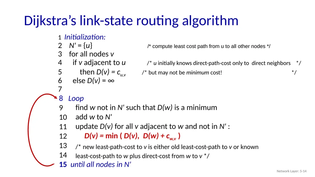
slide14. Dijkstra’s link-state routing algorithm Network Layer: 5-14 1 Initialization:
2 N' = {u} /* compute least cost path from u to all other nodes */
3 for all nodes v
4 if v adjacent to u /* u initially knows direct-path-cost only to direct neighbors */
5 then D(v) = cu,v /* but may not be minimum cost! */
6 else D(v) = ∞
7 8 Loop
9
10
11
12
13
14
15 until all nodes in N' find w not in N' such that D(w) is a minimum
add w to N'
update D(v) for all v adjacent to w and not in N' :
D(v) = min ( D(v), D(w) + cw,v )
/* new least-path-cost to v is either old least-cost-path to v or known
least-cost-path to w plus direct-cost from w to v */<br>
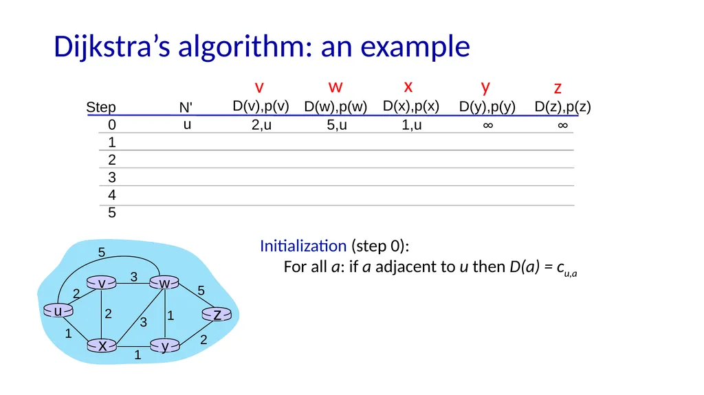
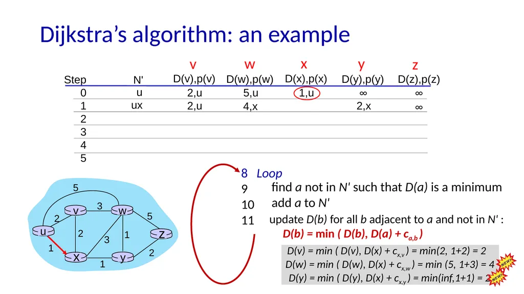
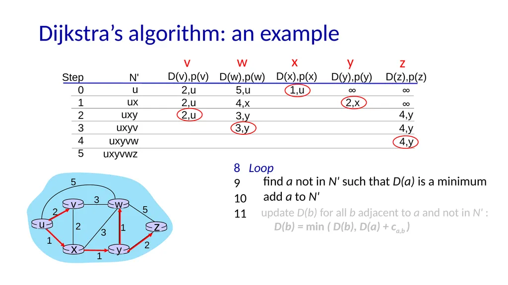
slide15. Dijkstra’s algorithm: an example Step
0
1
2
3
4
5 N' D(v),p(v) D(x),p(x) D(y),p(y) D(z),p(z) D(w),p(w) D(w),p(w)
5,u
4,x
3,y
3,y u v w x y z Initialization (step 0):
For all a: if a adjacent to u then D(a) = cu,a<br>
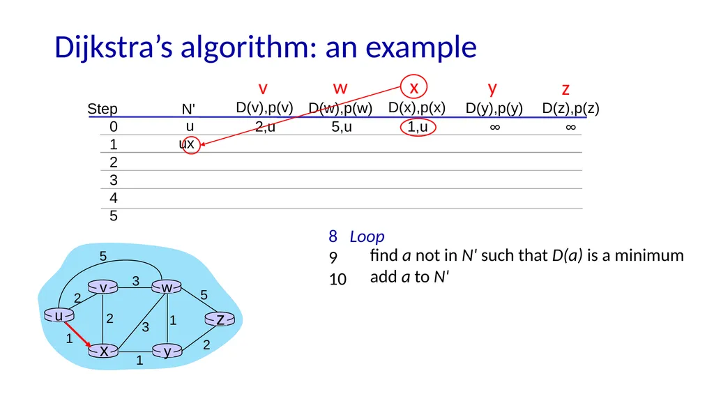
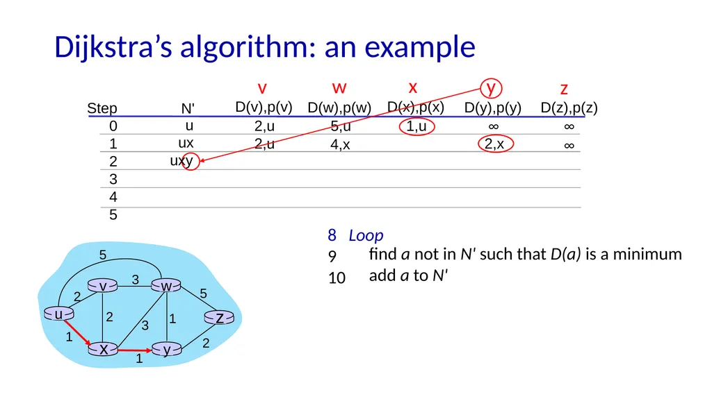
slide16. Dijkstra’s algorithm: an example Step
0
1
2
3
4
5 N' D(v),p(v) D(x),p(x) D(y),p(y) D(z),p(z) D(w),p(w) D(w),p(w)
5,u
4,x
3,y
3,y u 8 Loop
9
10 find a not in N' such that D(a) is a minimum
add a to N' ux v w x y z<br>
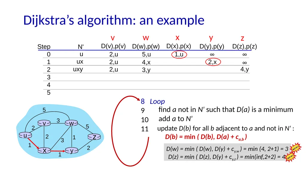
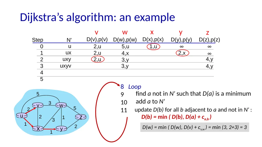
slide17. Dijkstra’s algorithm: an example Step
0
1
2
3
4
5 N' D(v),p(v) D(x),p(x) D(y),p(y) D(z),p(z) D(w),p(w) D(w),p(w)
5,u
4,x
3,y
3,y u 8 Loop
9
10
11 find a not in N' such that D(a) is a minimum
add a to N' ux v w x y z update D(b) for all b adjacent to a and not in N' :
D(b) = min ( D(b), D(a) + ca,b )<br>
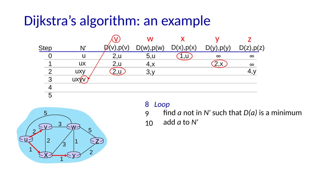
slide18. Dijkstra’s algorithm: an example Step
0
1
2
3
4
5 N' D(v),p(v) D(x),p(x) D(y),p(y) D(z),p(z) D(w),p(w) D(w),p(w)
5,u
4,x
3,y
3,y u 8 Loop
9
10 find a not in N' such that D(a) is a minimum
add a to N' ux v w x y z ∞ 2,x 4,x 2,u uxy<br>
slide19. Dijkstra’s algorithm: an example Step
0
1
2
3
4
5 N' D(v),p(v) D(x),p(x) D(y),p(y) D(z),p(z) D(w),p(w) u 8 Loop
9
10
11 find a not in N' such that D(a) is a minimum
add a to N' ux v w x y z uxy update D(b) for all b adjacent to a and not in N' :
D(b) = min ( D(b), D(a) + ca,b )<br>
slide20. Dijkstra’s algorithm: an example Step
0
1
2
3
4
5 N' D(v),p(v) D(x),p(x) D(y),p(y) D(z),p(z) D(w),p(w) u 8 Loop
9
10 find a not in N' such that D(a) is a minimum
add a to N' ux v w x y z uxy uxyv<br>
slide21. update D(b) for all b adjacent to a and not in N' :
D(b) = min ( D(b), D(a) + ca,b ) Dijkstra’s algorithm: an example Step
0
1
2
3
4
5 N' D(v),p(v) D(x),p(x) D(y),p(y) D(z),p(z) D(w),p(w) u 8 Loop
9
10
11 find a not in N' such that D(a) is a minimum
add a to N' ux v w x y z uxy uxyv<br>
slide22. Dijkstra’s algorithm: an example Step
0
1
2
3
4
5 N' D(v),p(v) D(x),p(x) D(y),p(y) D(z),p(z) D(w),p(w) u 8 Loop
9
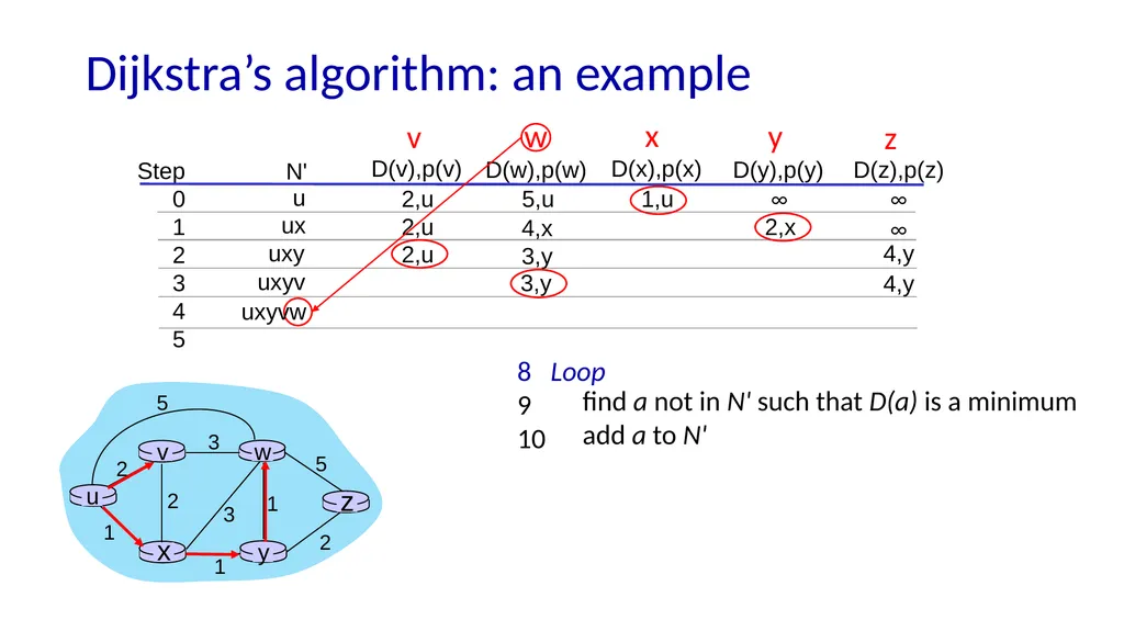
10 find a not in N' such that D(a) is a minimum
add a to N' ux v w x y z uxy uxyv uxyvw<br>
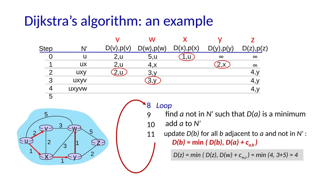
slide23. update D(b) for all b adjacent to a and not in N' :
D(b) = min ( D(b), D(a) + ca,b ) Dijkstra’s algorithm: an example Step
0
1
2
3
4
5 N' D(v),p(v) D(x),p(x) D(y),p(y) D(z),p(z) D(w),p(w) u 8 Loop
9
10
11 find a not in N' such that D(a) is a minimum
add a to N' ux v w x y z uxy uxyv uxyvw 4,y<br>
slide24. Dijkstra’s algorithm: an example Step
0
1
2
3
4
5 N' D(v),p(v) D(x),p(x) D(y),p(y) D(z),p(z) D(w),p(w) u 8 Loop
9
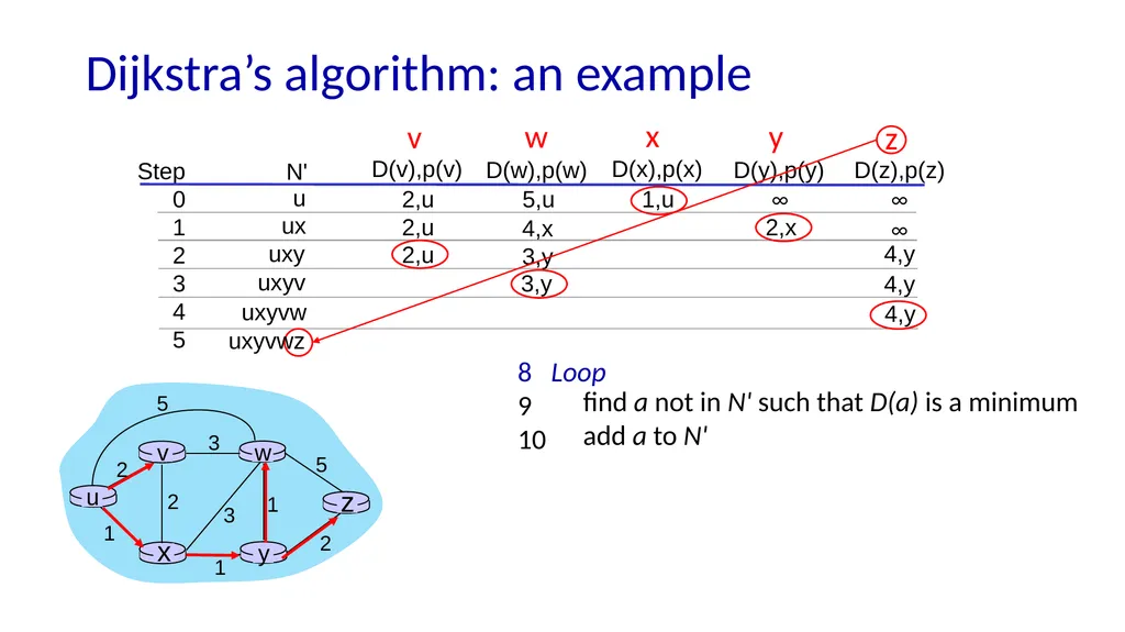
10 find a not in N' such that D(a) is a minimum
add a to N' ux v w x y z uxy uxyv uxyvw 4,y uxyvwz<br>
slide25. Dijkstra’s algorithm: an example Step
0
1
2
3
4
5 N' D(v),p(v) D(x),p(x) D(y),p(y) D(z),p(z) D(w),p(w) u 8 Loop
9
10
11 find a not in N' such that D(a) is a minimum
add a to N' ux v w x y z uxy uxyv uxyvw 4,y uxyvwz update D(b) for all b adjacent to a and not in N' :
D(b) = min ( D(b), D(a) + ca,b )<br>
slide26. Dijkstra’s algorithm: an example Network Layer: 5-26 Step
0
1
2
3
4
5 N' D(v),p(v) D(x),p(x) D(y),p(y) D(z),p(z) 4,y D(w),p(w) D(w),p(w)
5,u
4,x
3,y
3,y uxyvwz uxyvw uxyv uxy ux u v w x y z find a not in N' such that D(a) is a minimum
add a to N'
update D(b) for all b adjacent to a and not in N' :
D(b) = min ( D(b), D(a) + ca,b ) Initialization (step 0): For all a: if a adjacent to then D(a) = cu,a<br>
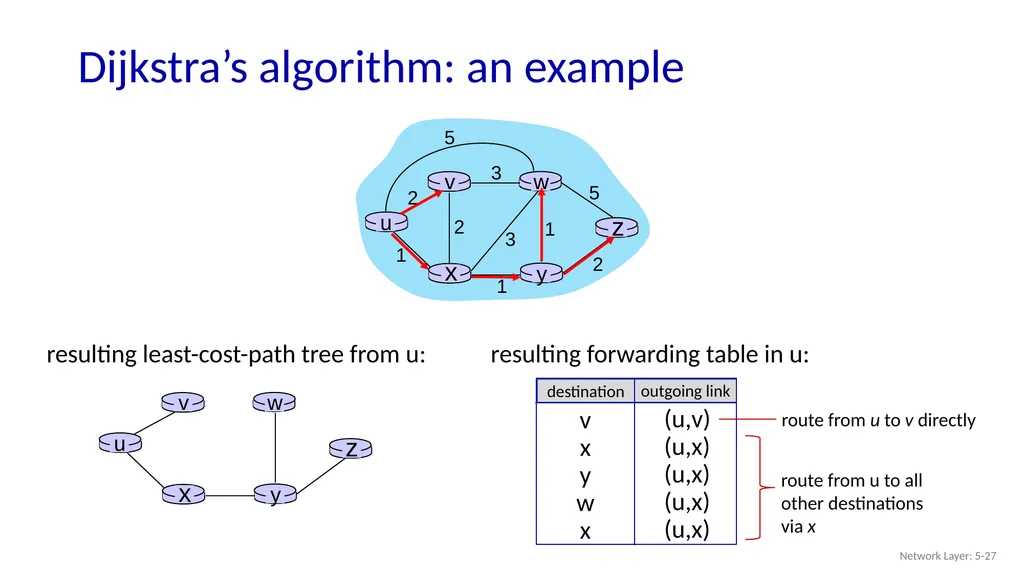
slide27. Dijkstra’s algorithm: an example Network Layer: 5-27 D(w),p(w)
5,u
4,x
3,y
3,y resulting least-cost-path tree from u:<br>
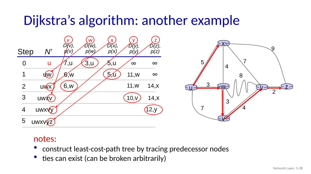
slide28. Dijkstra’s algorithm: another example Network Layer: 5-28 Step N' D(v),
p(v) 0 1 2 3 4 5 D(w),
p(w) D(x),
p(x) D(y),
p(y) D(z),
p(z) u uw uwx uwxv uwxvy 12,y notes:
construct least-cost-path tree by tracing predecessor nodes
ties can exist (can be broken arbitrarily) uwxvyz v w x y z<br>
slide29. Dijkstra’s algorithm: discussion Network Layer: 5-29 algorithm complexity: n nodes
each of n iteration: need to check all nodes, w, not in N
n(n+1)/2 comparisons: O(n2) complexity
more efficient implementations possible: O(nlogn) message complexity:
each router must broadcast its link state information to other n routers
efficient (and interesting!) broadcast algorithms: O(n) link crossings to disseminate a broadcast message from one source
each router’s message crosses O(n) links: overall message complexity: O(n2)<br>
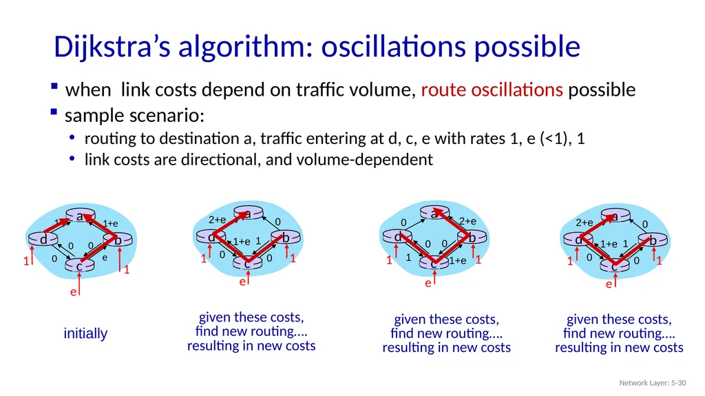
slide30. Dijkstra’s algorithm: oscillations possible Network Layer: 5-30 when link costs depend on traffic volume, route oscillations possible 1 1+e e 0 0 0 initially sample scenario:
routing to destination a, traffic entering at d, c, e with rates 1, e (<1), 1
link costs are directional, and volume-dependent<br>
slide31. Network layer: “control plane” roadmap network management, configuration
SNMP
NETCONF/YANG introduction
routing protocols
link state
distance vector
intra-ISP routing: OSPF
routing among ISPs: BGP
SDN control plane
Internet Control Message Protocol Network Layer: 5-31<br>
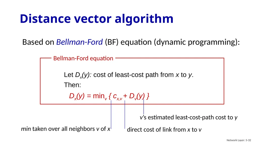
slide32. Based on Bellman-Ford (BF) equation (dynamic programming): Distance vector algorithm Network Layer: 5-32<br>
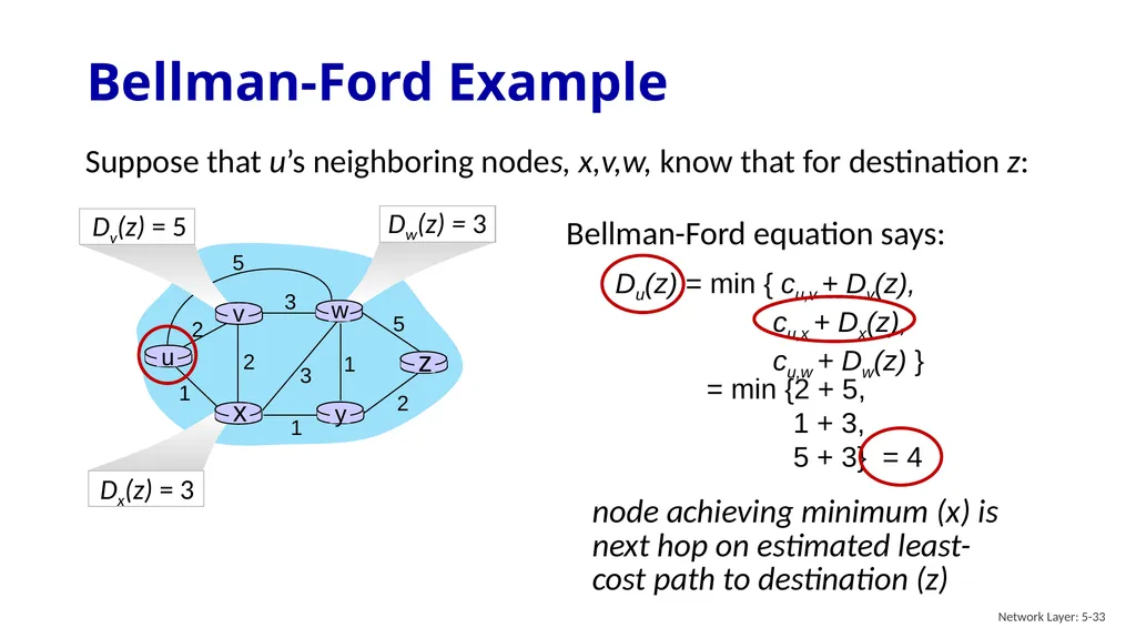
slide33. Bellman-Ford Example Network Layer: 5-33 2 2 1 3 1 1 2 5 3 5 Suppose that u’s neighboring nodes, x,v,w, know that for destination z: = min {2 + 5,
1 + 3,
5 + 3} = 4<br>
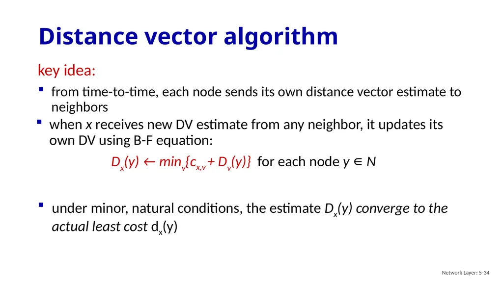
slide34. Distance vector algorithm Network Layer: 5-34 key idea:
from time-to-time, each node sends its own distance vector estimate to neighbors under minor, natural conditions, the estimate Dx(y) converge to the actual least cost dx(y)<br>
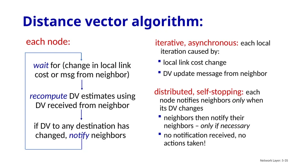
slide35. Distance vector algorithm: Network Layer: 5-35 iterative, asynchronous: each local iteration caused by:
local link cost change
DV update message from neighbor wait for (change in local link cost or msg from neighbor) each node: distributed, self-stopping: each node notifies neighbors only when its DV changes
neighbors then notify their neighbors – only if necessary
no notification received, no actions taken!<br>
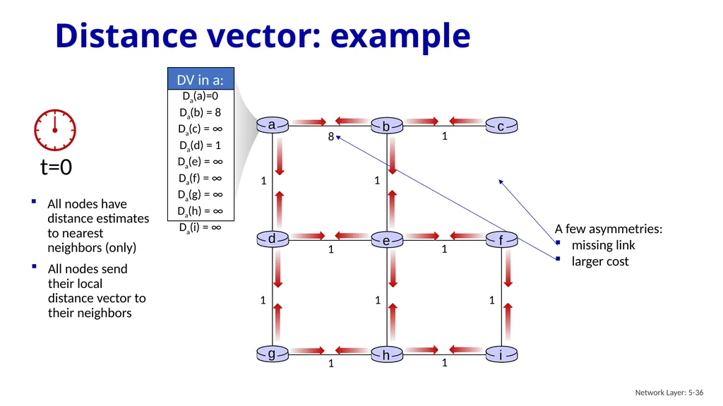
slide36. Distance vector: example Network Layer: 5-36 1 1 1 1 1 1 1 1 1 8 1 All nodes have distance estimates to nearest neighbors (only) All nodes send their local distance vector to their neighbors<br>
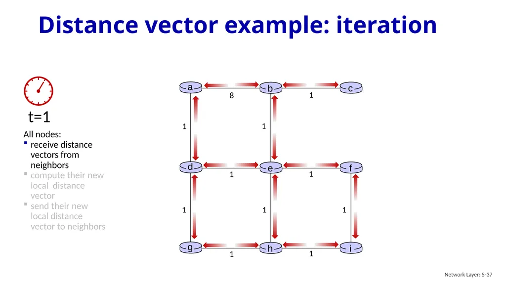
slide37. Distance vector example: iteration Network Layer: 5-37 All nodes:
receive distance vectors from neighbors
compute their new local distance vector
send their new local distance vector to neighbors 1 1 1 1 1 1 1 1 1 8 1<br>
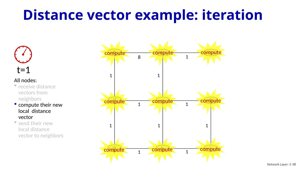
slide38. Distance vector example: iteration Network Layer: 5-38 1 1 1 1 1 1 1 1 1 8 1 All nodes:
receive distance vectors from neighbors
compute their new local distance vector
send their new local distance vector to neighbors<br>
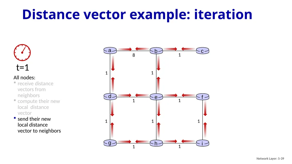
slide39. Distance vector example: iteration Network Layer: 5-39 1 1 1 1 1 1 1 1 1 8 1 All nodes:
receive distance vectors from neighbors
compute their new local distance vector
send their new local distance vector to neighbors<br>
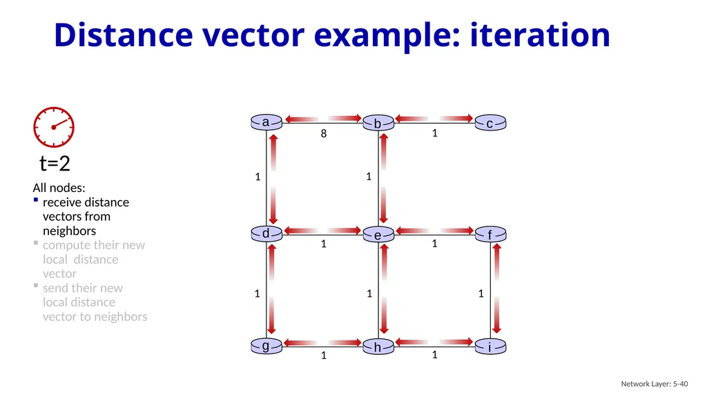
slide40. Distance vector example: iteration Network Layer: 5-40 1 1 1 1 1 1 1 1 1 8 1 All nodes:
receive distance vectors from neighbors
compute their new local distance vector
send their new local distance vector to neighbors<br>
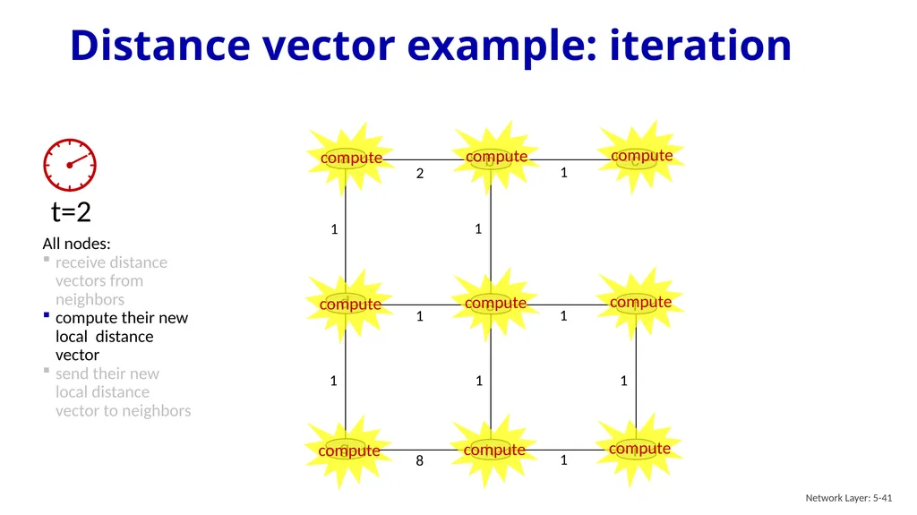
slide41. Distance vector example: iteration Network Layer: 5-41 1 1 1 1 1 1 1 8 1 2 1 All nodes:
receive distance vectors from neighbors
compute their new local distance vector
send their new local distance vector to neighbors<br>
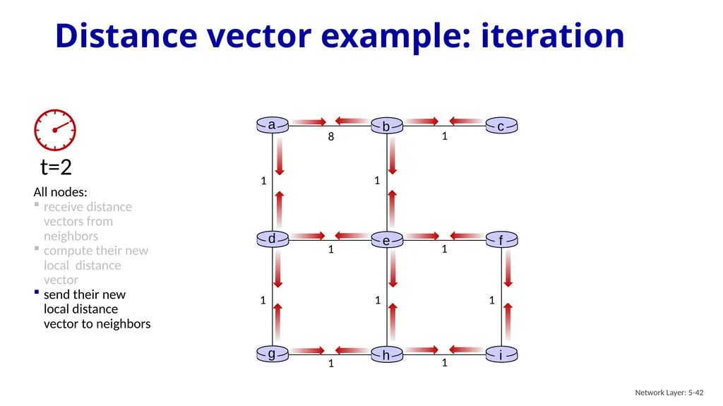
slide42. Distance vector example: iteration Network Layer: 5-42 1 1 1 1 1 1 1 1 1 8 1 All nodes:
receive distance vectors from neighbors
compute their new local distance vector
send their new local distance vector to neighbors<br>
slide43. Distance vector example: iteration Network Layer: 5-43 …. and so on
Let’s next take a look at the iterative computations at nodes<br>
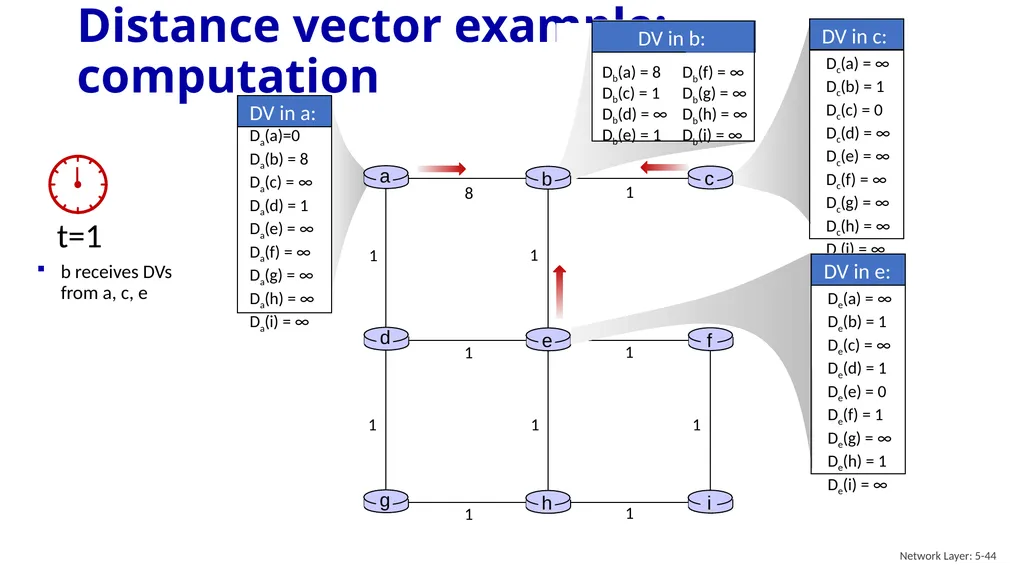
slide44. Distance vector example: computation Network Layer: 5-44 1 1 1 1 1 1 1 1 1 8 1 b receives DVs from a, c, e<br>
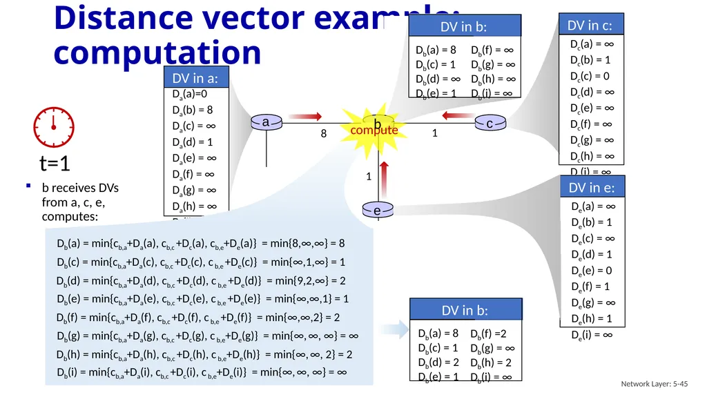
slide45. Distance vector example: computation Network Layer: 5-45 1 1 1 1 1 1 1 1 1 8 1 b receives DVs from a, c, e, computes: b Db(a) = min{cb,a+Da(a), cb,c +Dc(a), cb,e+De(a)} = min{8,∞,∞} = 8 Db(c) = min{cb,a+Da(c), cb,c +Dc(c), c b,e +De(c)} = min{∞,1,∞} = 1 Db(d) = min{cb,a+Da(d), cb,c +Dc(d), c b,e +De(d)} = min{9,2,∞} = 2 Db(f) = min{cb,a+Da(f), cb,c +Dc(f), c b,e +De(f)} = min{∞,∞,2} = 2 Db(i) = min{cb,a+Da(i), cb,c +Dc(i), c b,e+De(i)} = min{∞, ∞, ∞} = ∞ Db(h) = min{cb,a+Da(h), cb,c +Dc(h), c b,e+De(h)} = min{∞, ∞, 2} = 2 Db(e) = min{cb,a+Da(e), cb,c +Dc(e), c b,e +De(e)} = min{∞,∞,1} = 1 Db(g) = min{cb,a+Da(g), cb,c +Dc(g), c b,e+De(g)} = min{∞, ∞, ∞} = ∞<br>
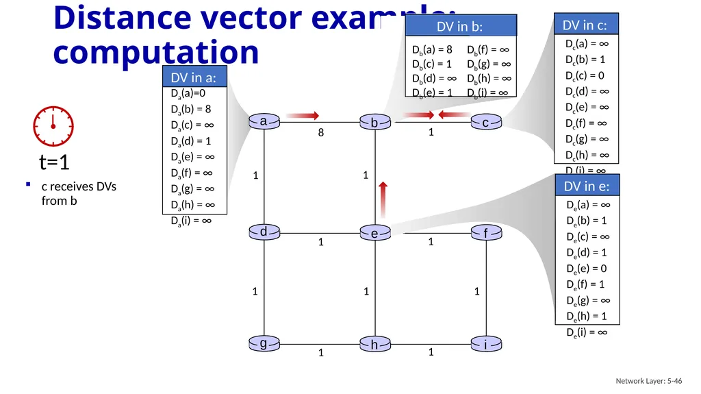
slide46. Distance vector example: computation Network Layer: 5-46 1 1 1 1 1 1 1 1 1 8 1 c receives DVs from b<br>
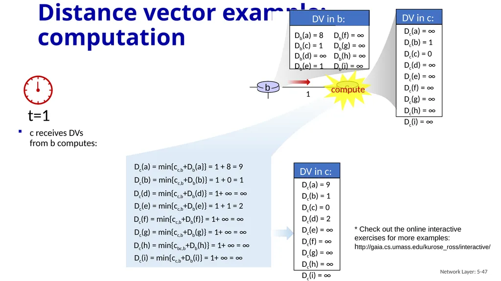
slide47. Distance vector example: computation Network Layer: 5-47 1 1 8 1 c receives DVs from b computes: Dc(a) = min{cc,b+Db(a}} = 1 + 8 = 9 Dc(b) = min{cc,b+Db(b)} = 1 + 0 = 1 Dc(d) = min{cc,b+Db(d)} = 1+ ∞ = ∞ Dc(e) = min{cc,b+Db(e)} = 1 + 1 = 2 Dc(f) = min{cc,b+Db(f)} = 1+ ∞ = ∞ Dc(g) = min{cc,b+Db(g)} = 1+ ∞ = ∞ Dc(i) = min{cc,b+Db(i)} = 1+ ∞ = ∞ Dc(h) = min{cbc,b+Db(h)} = 1+ ∞ = ∞ * Check out the online interactive exercises for more examples: http://gaia.cs.umass.edu/kurose_ross/interactive/<br>
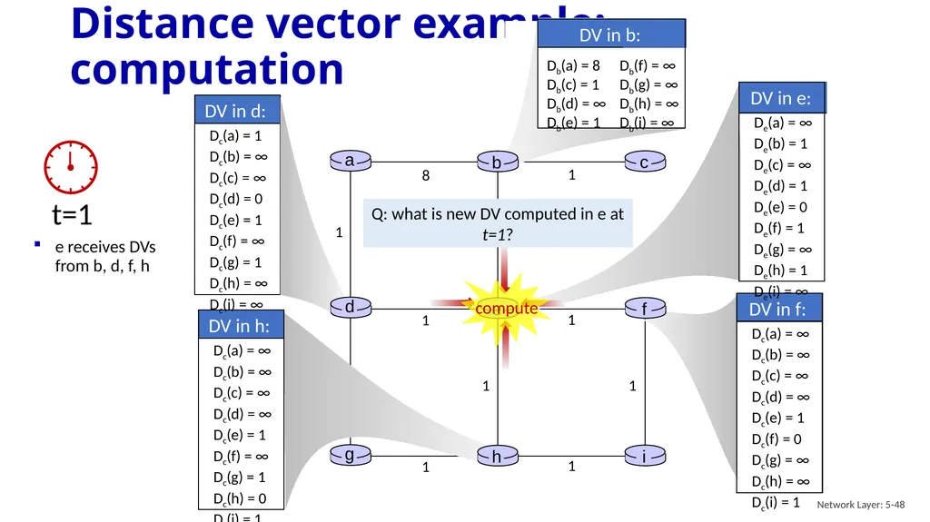
slide48. Distance vector example: computation Network Layer: 5-48 1 1 1 1 1 1 1 1 1 8 1 e receives DVs from b, d, f, h Q: what is new DV computed in e at t=1?<br>
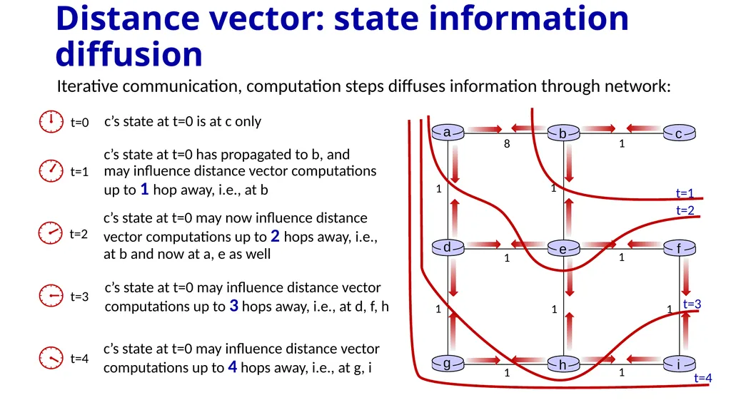
slide49. Distance vector: state information diffusion Iterative communication, computation steps diffuses information through network:<br>
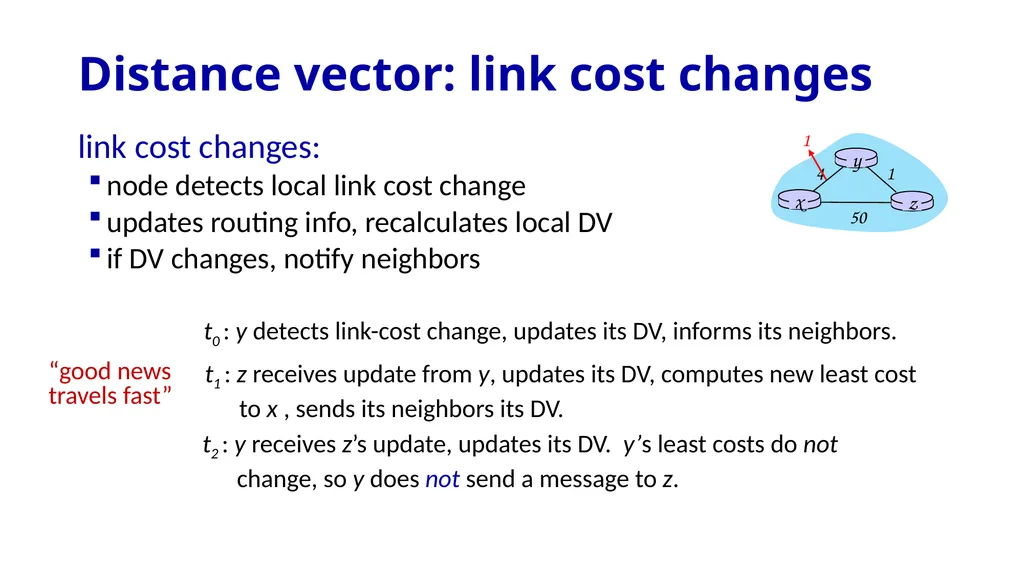
slide50. Distance vector: link cost changes “good news
travels fast” t0 : y detects link-cost change, updates its DV, informs its neighbors. t1 : z receives update from y, updates its DV, computes new least cost to x , sends its neighbors its DV. t2 : y receives z’s update, updates its DV. y’s least costs do not change, so y does not send a message to z. link cost changes:
node detects local link cost change
updates routing info, recalculates local DV
if DV changes, notify neighbors<br>
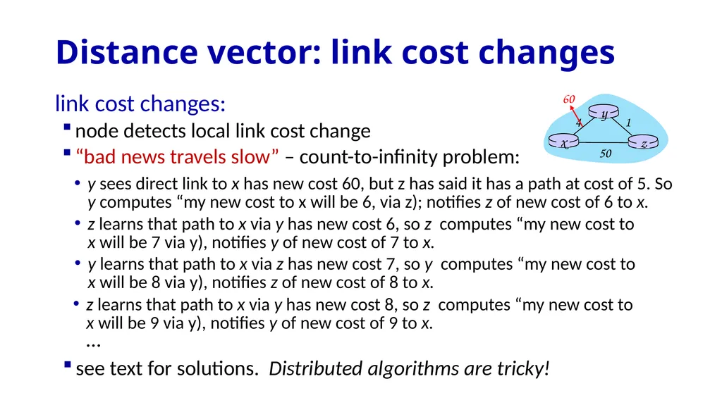
slide51. Distance vector: link cost changes link cost changes:
node detects local link cost change
“bad news travels slow” – count-to-infinity problem: y sees direct link to x has new cost 60, but z has said it has a path at cost of 5. So y computes “my new cost to x will be 6, via z); notifies z of new cost of 6 to x. z learns that path to x via y has new cost 6, so z computes “my new cost to x will be 7 via y), notifies y of new cost of 7 to x. y learns that path to x via z has new cost 7, so y computes “my new cost to x will be 8 via y), notifies z of new cost of 8 to x. z learns that path to x via y has new cost 8, so z computes “my new cost to x will be 9 via y), notifies y of new cost of 9 to x. … see text for solutions. Distributed algorithms are tricky!<br>
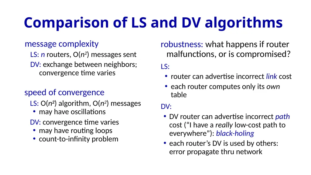
slide52. Comparison of LS and DV algorithms message complexity
LS: n routers, O(n2) messages sent
DV: exchange between neighbors; convergence time varies speed of convergence
LS: O(n2) algorithm, O(n2) messages
may have oscillations
DV: convergence time varies
may have routing loops
count-to-infinity problem robustness: what happens if router malfunctions, or is compromised?
LS:
router can advertise incorrect link cost
each router computes only its own table
DV:
DV router can advertise incorrect path cost (“I have a really low-cost path to everywhere”): black-holing
each router’s DV is used by others: error propagate thru network<br>
slide53. Network layer: “control plane” roadmap network management, configuration
SNMP
NETCONF/YANG introduction
routing protocols
intra-ISP routing: OSPF
routing among ISPs: BGP
SDN control plane
Internet Control Message Protocol Network Layer: 5-53<br>
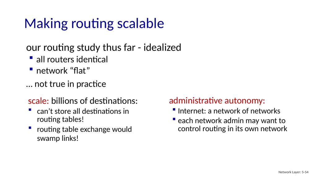
slide54. our routing study thus far - idealized
all routers identical
network “flat”
… not true in practice Making routing scalable Network Layer: 5-54 scale: billions of destinations:
can’t store all destinations in routing tables!
routing table exchange would swamp links! administrative autonomy:
Internet: a network of networks
each network admin may want to control routing in its own network<br>
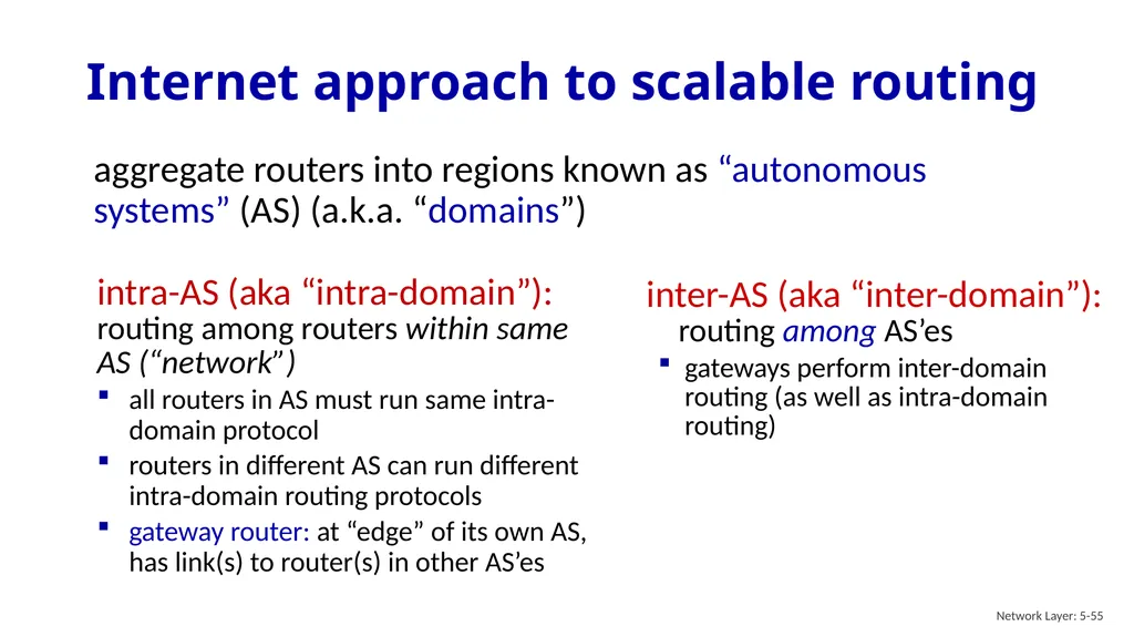
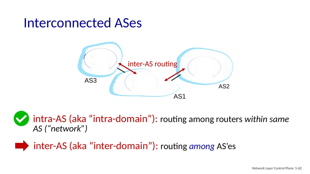
slide55. aggregate routers into regions known as “autonomous systems” (AS) (a.k.a. “domains”) Internet approach to scalable routing Network Layer: 5-55 intra-AS (aka “intra-domain”): routing among routers within same AS (“network”)
all routers in AS must run same intra-domain protocol
routers in different AS can run different intra-domain routing protocols
gateway router: at “edge” of its own AS, has link(s) to router(s) in other AS’es inter-AS (aka “inter-domain”): routing among AS’es
gateways perform inter-domain routing (as well as intra-domain routing)<br>
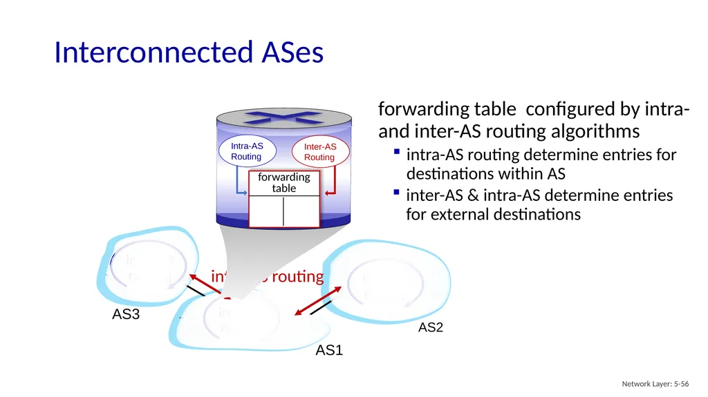
slide56. Interconnected ASes Network Layer: 5-56 3b 3a 2a AS3 AS1 AS2 1a forwarding table configured by intra- and inter-AS routing algorithms intra-AS routing determine entries for destinations within AS inter-AS & intra-AS determine entries for external destinations<br>
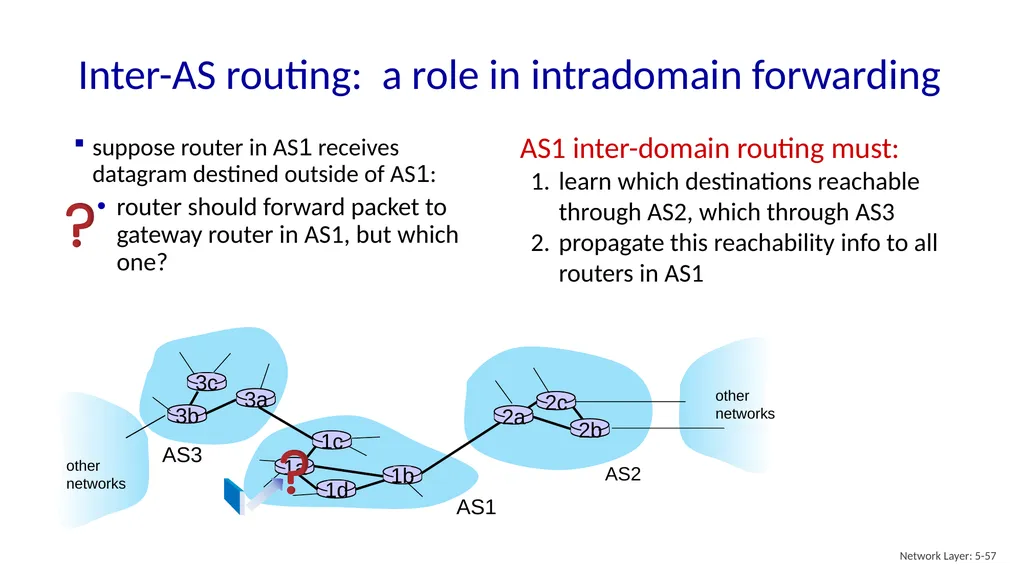
slide57. Inter-AS routing: a role in intradomain forwarding Network Layer: 5-57 3b 3a 2a AS3 AS1 AS2 1a other
networks other
networks suppose router in AS1 receives datagram destined outside of AS1: AS1 inter-domain routing must:
learn which destinations reachable through AS2, which through AS3
propagate this reachability info to all routers in AS1 router should forward packet to gateway router in AS1, but which one?<br>
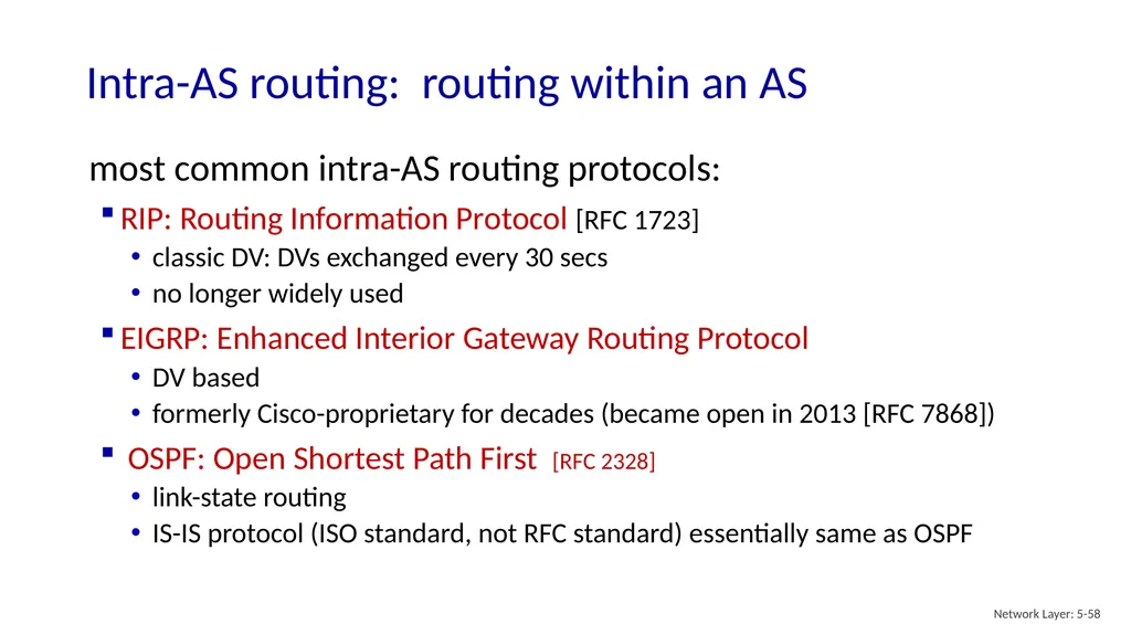
slide58. Intra-AS routing: routing within an AS Network Layer: 5-58 most common intra-AS routing protocols:
RIP: Routing Information Protocol [RFC 1723]
classic DV: DVs exchanged every 30 secs
no longer widely used
EIGRP: Enhanced Interior Gateway Routing Protocol
DV based
formerly Cisco-proprietary for decades (became open in 2013 [RFC 7868])
OSPF: Open Shortest Path First [RFC 2328]
link-state routing
IS-IS protocol (ISO standard, not RFC standard) essentially same as OSPF<br>
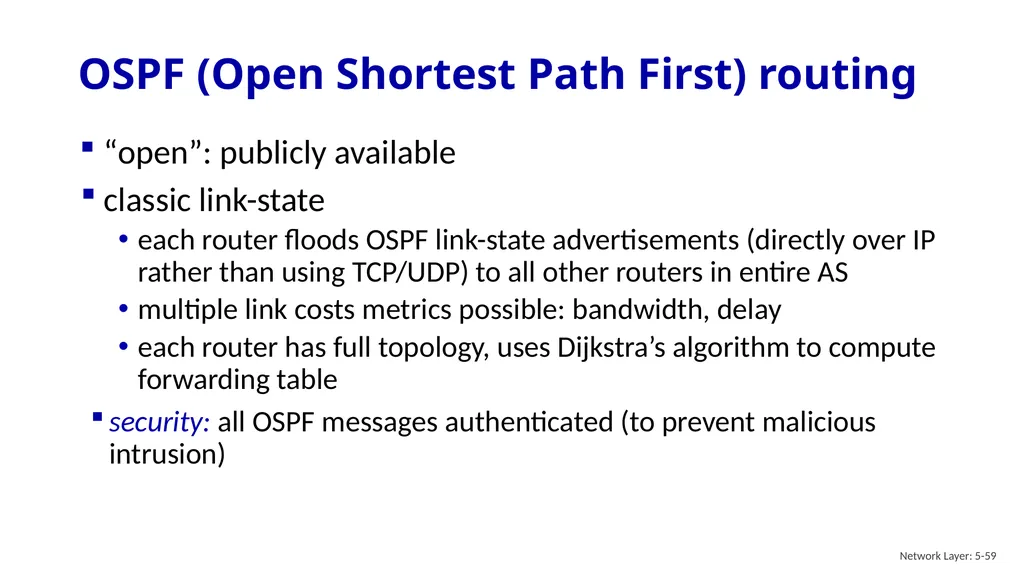
slide59. OSPF (Open Shortest Path First) routing Network Layer: 5-59 “open”: publicly available
classic link-state
each router floods OSPF link-state advertisements (directly over IP rather than using TCP/UDP) to all other routers in entire AS
multiple link costs metrics possible: bandwidth, delay
each router has full topology, uses Dijkstra’s algorithm to compute forwarding table
security: all OSPF messages authenticated (to prevent malicious intrusion)<br>
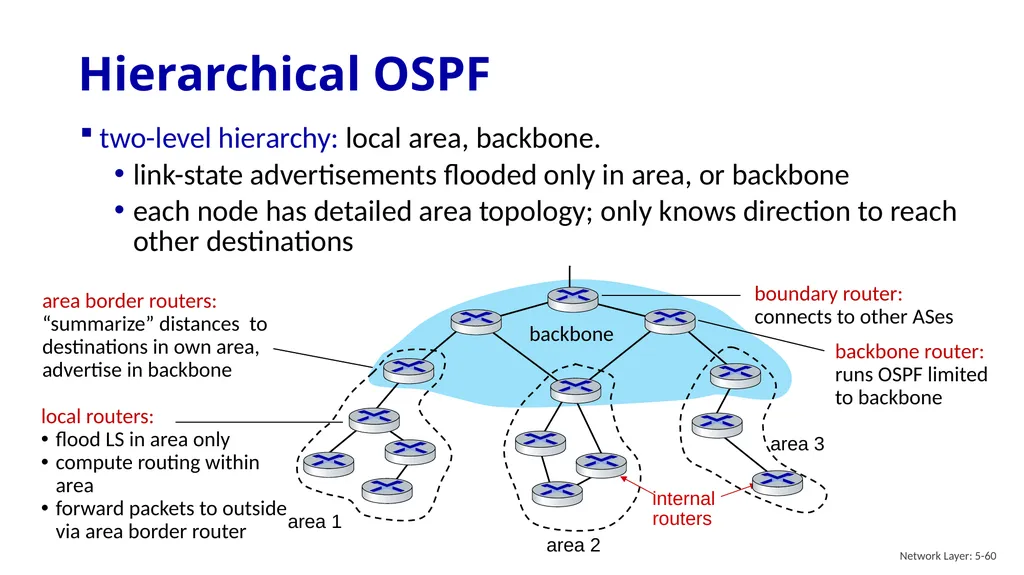
slide60. Hierarchical OSPF Network Layer: 5-60 two-level hierarchy: local area, backbone.
link-state advertisements flooded only in area, or backbone
each node has detailed area topology; only knows direction to reach other destinations area 1 area 2 area 3 backbone internal
routers<br>
slide61. Network layer: “control plane” roadmap network management, configuration
SNMP
NETCONF/YANG introduction
routing protocols
intra-ISP routing: OSPF
routing among ISPs: BGP
SDN control plane
Internet Control Message Protocol Network Layer: 5-61<br>
slide62. Interconnected ASes 3b 3a 2a AS3 AS1 AS2 1a Network Layer Control Plane: 5-62<br>
slide63. BGP (Border Gateway Protocol): the de facto inter-domain routing protocol
“glue that holds the Internet together”
allows subnet to advertise its existence, and the destinations it can reach, to rest of Internet: “I am here, here is who I can reach, and how”
BGP provides each AS a means to:
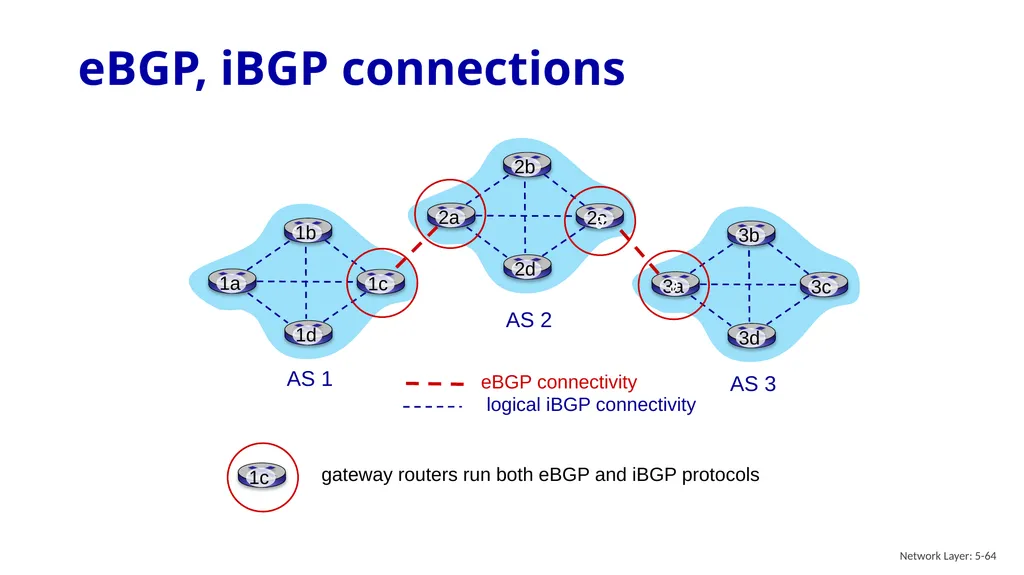
obtain destination network reachability info from neighboring ASes (eBGP)
determine routes to other networks based on reachability information and policy
propagate reachability information to all AS-internal routers (iBGP)
advertise (to neighboring networks) destination reachability info Internet inter-AS routing: BGP Network Layer Control Plane: 5-63<br>
slide64. eBGP, iBGP connections Network Layer: 5-64 AS 2 AS 3 AS 1<br>
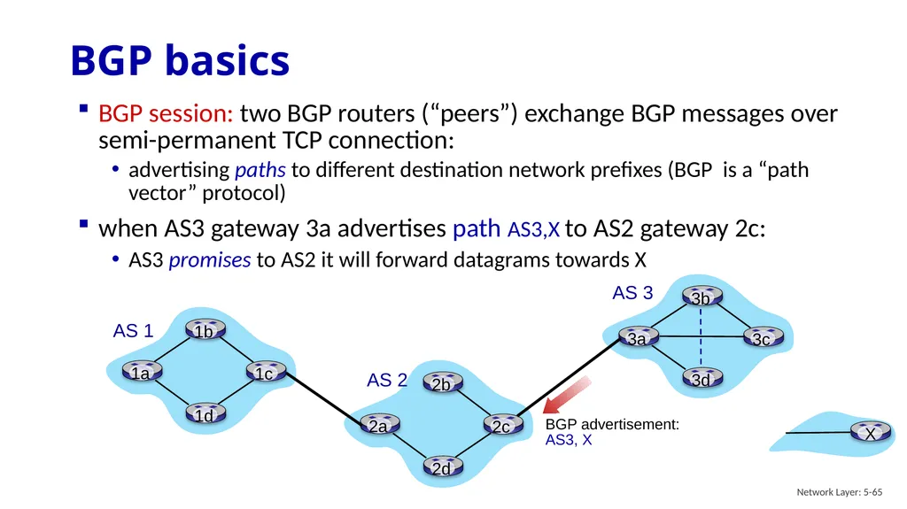
slide65. BGP basics Network Layer: 5-65 when AS3 gateway 3a advertises path AS3,X to AS2 gateway 2c:
AS3 promises to AS2 it will forward datagrams towards X BGP session: two BGP routers (“peers”) exchange BGP messages over semi-permanent TCP connection:
advertising paths to different destination network prefixes (BGP is a “path vector” protocol)<br>
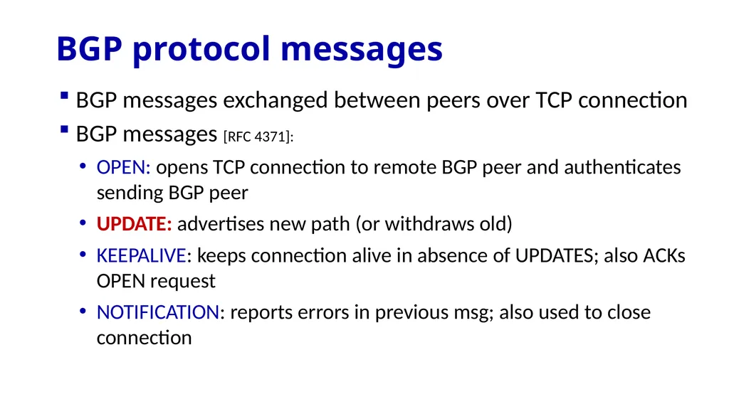
slide66. BGP protocol messages BGP messages exchanged between peers over TCP connection
BGP messages [RFC 4371]:
OPEN: opens TCP connection to remote BGP peer and authenticates sending BGP peer
UPDATE: advertises new path (or withdraws old)
KEEPALIVE: keeps connection alive in absence of UPDATES; also ACKs OPEN request
NOTIFICATION: reports errors in previous msg; also used to close connection<br>
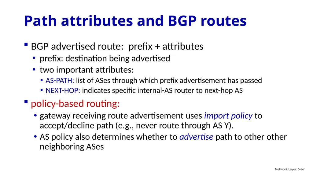
slide67. Path attributes and BGP routes Network Layer: 5-67 BGP advertised route: prefix + attributes
prefix: destination being advertised
two important attributes:
AS-PATH: list of ASes through which prefix advertisement has passed
NEXT-HOP: indicates specific internal-AS router to next-hop AS
policy-based routing:
gateway receiving route advertisement uses import policy to accept/decline path (e.g., never route through AS Y).
AS policy also determines whether to advertise path to other other neighboring ASes<br>
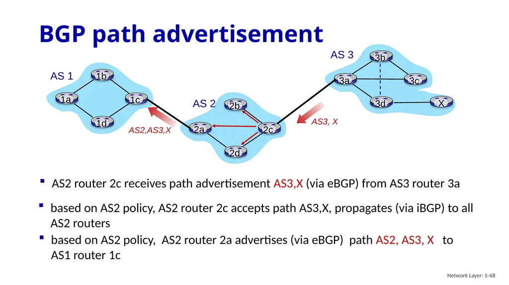
slide68. BGP path advertisement Network Layer: 5-68 based on AS2 policy, AS2 router 2c accepts path AS3,X, propagates (via iBGP) to all AS2 routers AS2 router 2c receives path advertisement AS3,X (via eBGP) from AS3 router 3a based on AS2 policy, AS2 router 2a advertises (via eBGP) path AS2, AS3, X to AS1 router 1c<br>
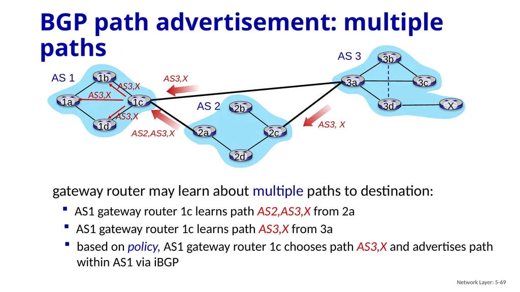
slide69. Network Layer: 5-69 AS1 gateway router 1c learns path AS2,AS3,X from 2a gateway router may learn about multiple paths to destination: AS1 gateway router 1c learns path AS3,X from 3a based on policy, AS1 gateway router 1c chooses path AS3,X and advertises path within AS1 via iBGP BGP path advertisement: multiple paths<br>
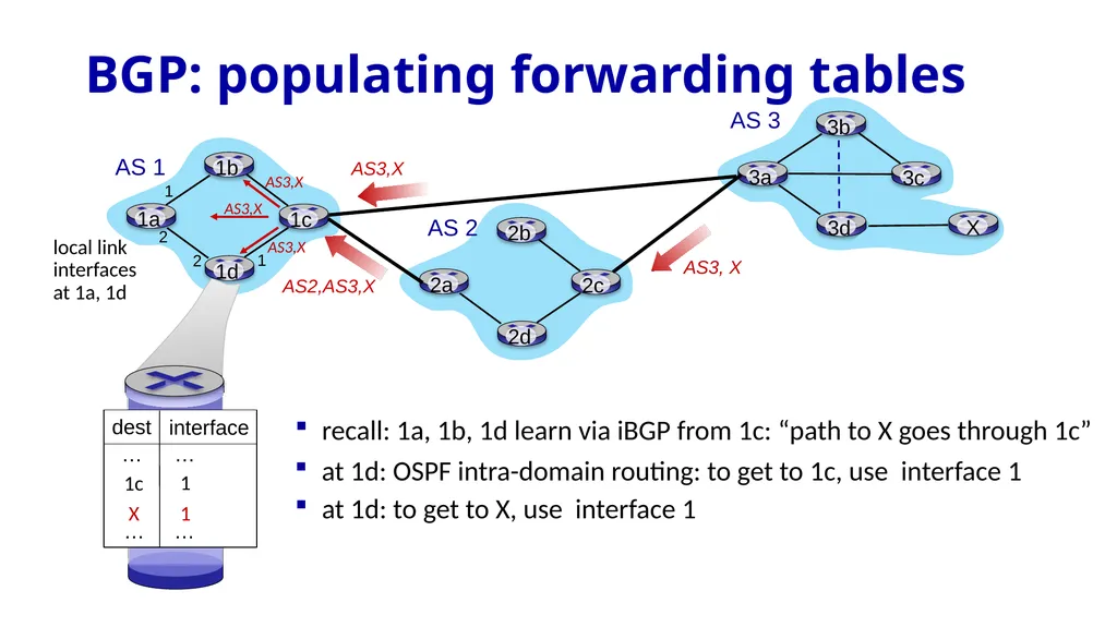
slide70. BGP: populating forwarding tables recall: 1a, 1b, 1d learn via iBGP from 1c: “path to X goes through 1c” at 1d: OSPF intra-domain routing: to get to 1c, use interface 1 local link interfaces
at 1a, 1d at 1d: to get to X, use interface 1<br>
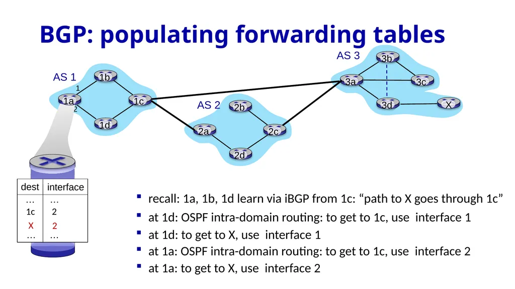
slide71. BGP: populating forwarding tables recall: 1a, 1b, 1d learn via iBGP from 1c: “path to X goes through 1c” at 1d: OSPF intra-domain routing: to get to 1c, use interface 1 at 1d: to get to X, use interface 1 at 1a: OSPF intra-domain routing: to get to 1c, use interface 2 at 1a: to get to X, use interface 2<br>
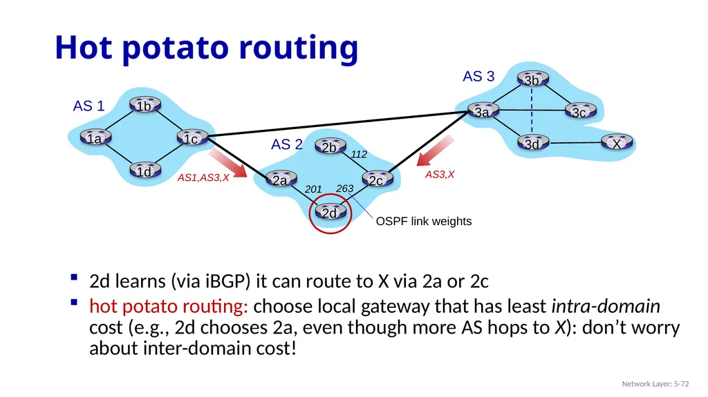
slide72. Hot potato routing Network Layer: 5-72 2d learns (via iBGP) it can route to X via 2a or 2c
hot potato routing: choose local gateway that has least intra-domain cost (e.g., 2d chooses 2a, even though more AS hops to X): don’t worry about inter-domain cost! OSPF link weights 201 112 263<br>
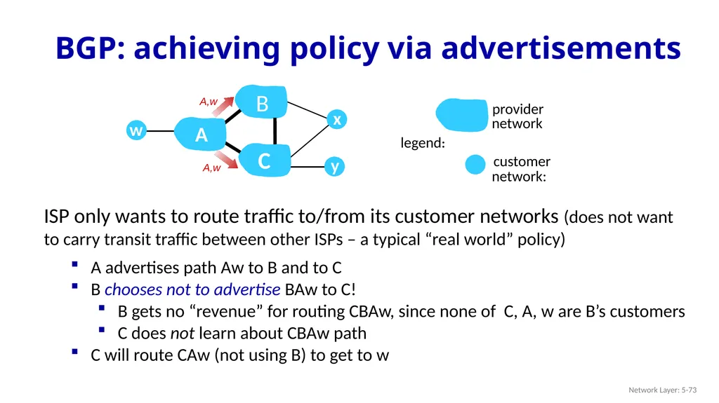
slide73. BGP: achieving policy via advertisements Network Layer: 5-73 A advertises path Aw to B and to C
B chooses not to advertise BAw to C!
B gets no “revenue” for routing CBAw, since none of C, A, w are B’s customers
C does not learn about CBAw path
C will route CAw (not using B) to get to w ISP only wants to route traffic to/from its customer networks (does not want to carry transit traffic between other ISPs – a typical “real world” policy) w y<br>
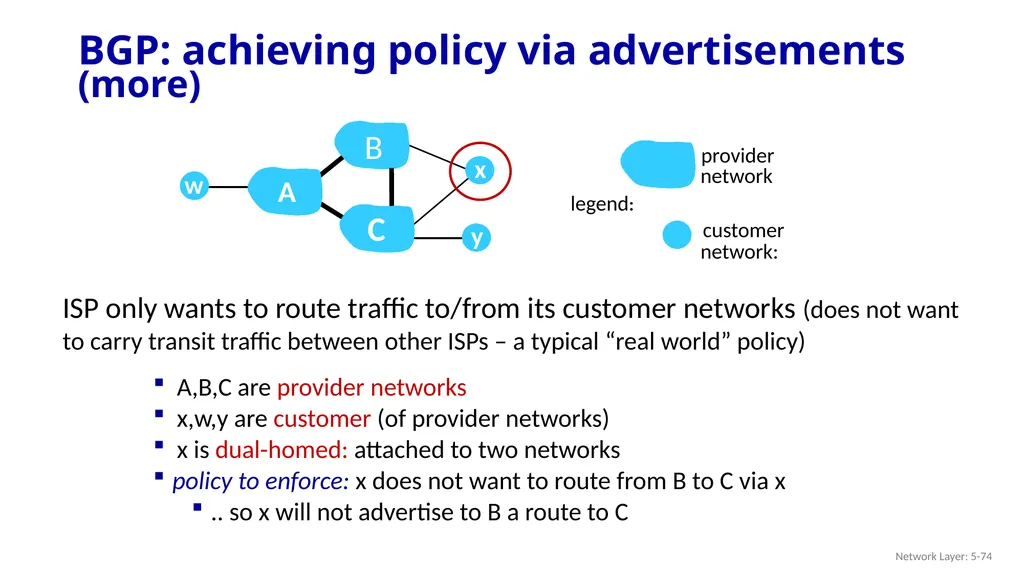
slide74. BGP: achieving policy via advertisements (more) Network Layer: 5-74 ISP only wants to route traffic to/from its customer networks (does not want to carry transit traffic between other ISPs – a typical “real world” policy) w y A,B,C are provider networks
x,w,y are customer (of provider networks)
x is dual-homed: attached to two networks
policy to enforce: x does not want to route from B to C via x
.. so x will not advertise to B a route to C<br>
slide75. router may learn about more than one route to destination AS, selects route based on:
local preference value attribute: policy decision
shortest AS-PATH
closest NEXT-HOP router: hot potato routing
additional criteria BGP route selection Network Layer: 5-75<br>
slide76. Why different Intra-, Inter-AS routing ? Network Layer: 5-76 policy:
inter-AS: admin wants control over how its traffic routed, who routes through its network
intra-AS: single admin, so policy less of an issue
scale:
hierarchical routing saves table size, reduced update traffic
performance:
intra-AS: can focus on performance
inter-AS: policy dominates over performance<br>
slide77. Network layer: “control plane” roadmap network management, configuration
SNMP
NETCONF/YANG introduction
routing protocols
intra-ISP routing: OSPF
routing among ISPs: BGP
SDN control plane
Internet Control Message Protocol Network Layer: 5-77<br>
slide78. Internet network layer: historically implemented via distributed, per-router control approach:
monolithic router contains switching hardware, runs proprietary implementation of Internet standard protocols (IP, RIP, IS-IS, OSPF, BGP) in proprietary router OS (e.g., Cisco IOS)
different “middleboxes” for different network layer functions: firewalls, load balancers, NAT boxes, ..
~2005: renewed interest in rethinking network control plane Software defined networking (SDN) Network Layer: 5-78<br>
slide79. Per-router control plane Individual routing algorithm components in each and every router interact in the control plane to compute forwarding tables 1 2 values in arriving
packet header 3 Network Layer: 4-79<br>
slide80. Software-Defined Networking (SDN) control plane Remote controller computes, installs forwarding tables in routers values in arriving
packet header Network Layer: 4-80<br>
slide81. Why a logically centralized control plane?
easier network management: avoid router misconfigurations, greater flexibility of traffic flows
table-based forwarding (recall OpenFlow API) allows “programming” routers
centralized “programming” easier: compute tables centrally and distribute
distributed “programming” more difficult: compute tables as result of distributed algorithm (protocol) implemented in each-and-every router
open (non-proprietary) implementation of control plane
foster innovation: let 1000 flowers bloom Software defined networking (SDN) Network Layer: 5-81<br>
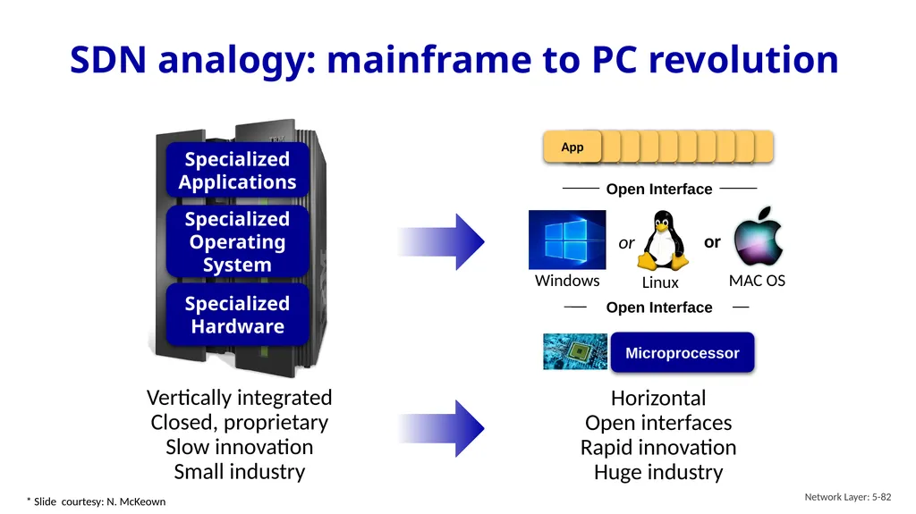
slide82. SDN analogy: mainframe to PC revolution Network Layer: 5-82 Vertically integrated
Closed, proprietary
Slow innovation
Small industry Specialized
Operating
System Specialized
Hardware Specialized
Applications Horizontal
Open interfaces
Rapid innovation
Huge industry * Slide courtesy: N. McKeown<br>
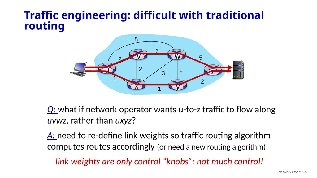
slide83. Traffic engineering: difficult with traditional routing Network Layer: 5-83 Q: what if network operator wants u-to-z traffic to flow along uvwz, rather than uxyz?
A: need to re-define link weights so traffic routing algorithm computes routes accordingly (or need a new routing algorithm)! link weights are only control “knobs”: not much control!<br>
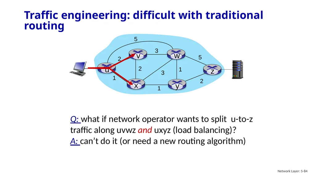
slide84. Traffic engineering: difficult with traditional routing Network Layer: 5-84 Q: what if network operator wants to split u-to-z traffic along uvwz and uxyz (load balancing)?
A: can’t do it (or need a new routing algorithm)<br>
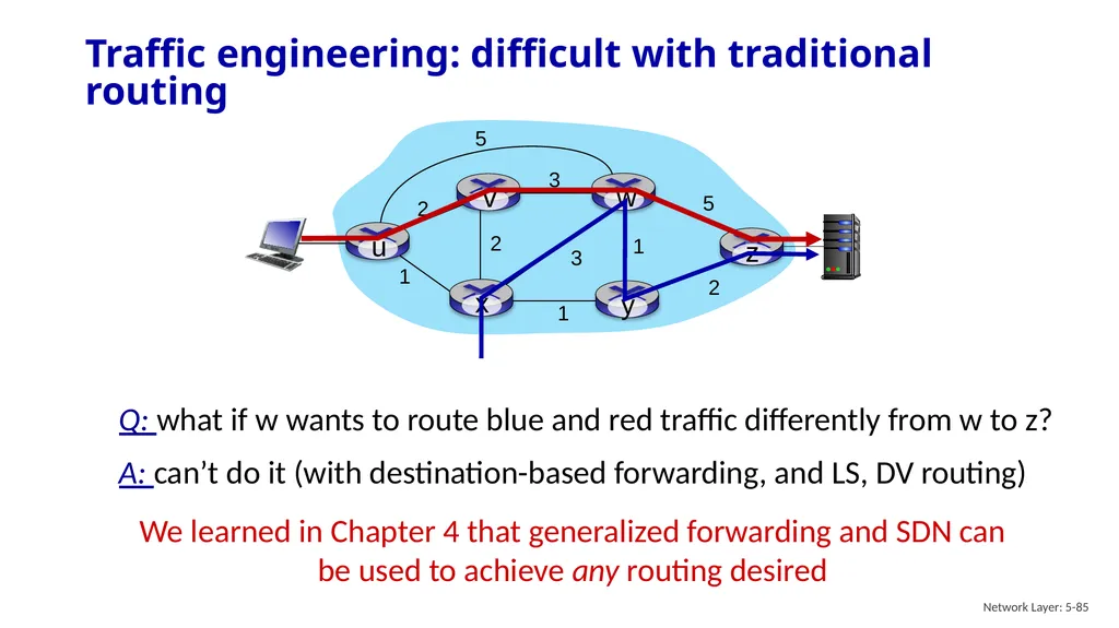
slide85. Traffic engineering: difficult with traditional routing Network Layer: 5-85 Q: what if w wants to route blue and red traffic differently from w to z?
A: can’t do it (with destination-based forwarding, and LS, DV routing) We learned in Chapter 4 that generalized forwarding and SDN can be used to achieve any routing desired<br>
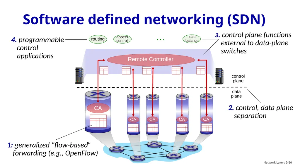
slide86. Software defined networking (SDN) Network Layer: 5-86 3. control plane functions external to data-plane switches … routing access control load
balance<br>
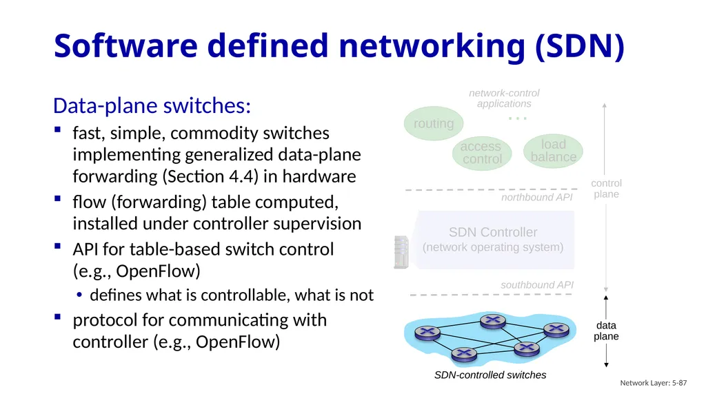
slide87. Software defined networking (SDN) Network Layer: 5-87 Data-plane switches:
fast, simple, commodity switches implementing generalized data-plane forwarding (Section 4.4) in hardware
flow (forwarding) table computed, installed under controller supervision
API for table-based switch control (e.g., OpenFlow)
defines what is controllable, what is not
protocol for communicating with controller (e.g., OpenFlow)<br>
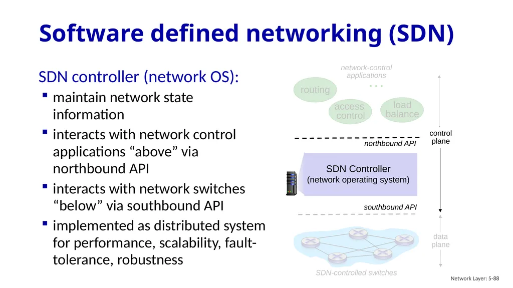
slide88. Software defined networking (SDN) Network Layer: 5-88 SDN controller (network OS):
maintain network state information
interacts with network control applications “above” via northbound API
interacts with network switches “below” via southbound API
implemented as distributed system for performance, scalability, fault-tolerance, robustness<br>
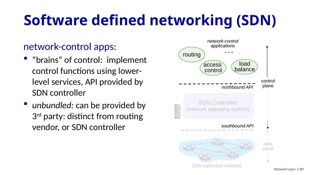
slide89. Software defined networking (SDN) Network Layer: 5-89 network-control apps:
“brains” of control: implement control functions using lower-level services, API provided by SDN controller
unbundled: can be provided by 3rd party: distinct from routing vendor, or SDN controller<br>
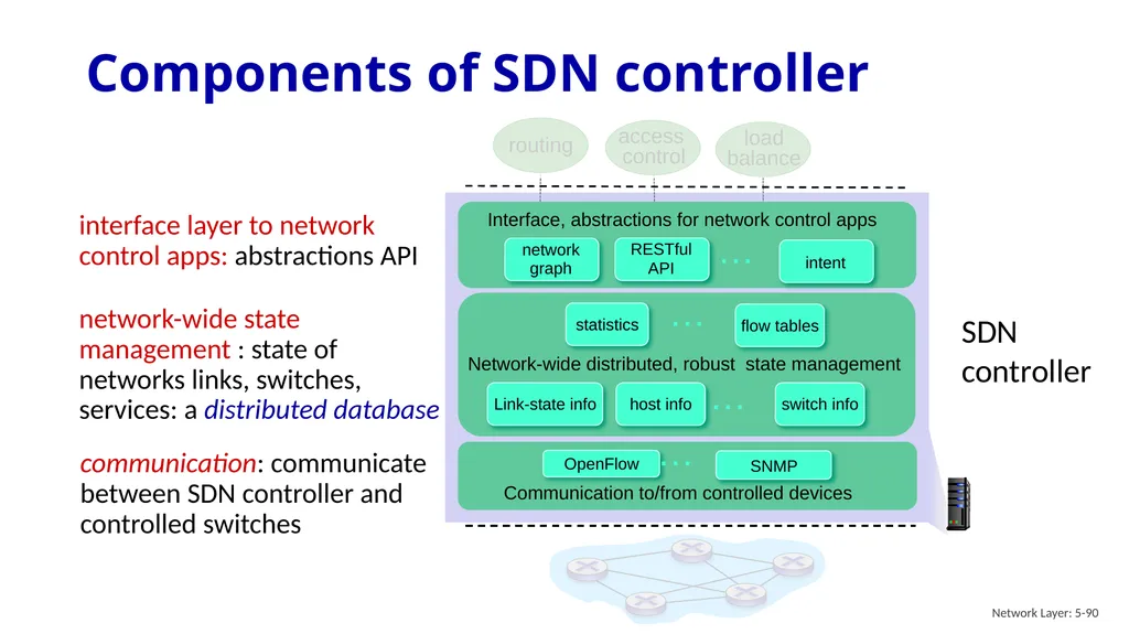
slide90. Components of SDN controller Network Layer: 5-90 Network-wide distributed, robust state management Communication to/from controlled devices … … … … Interface, abstractions for network control apps SDN
controller communication: communicate between SDN controller and controlled switches network-wide state management : state of networks links, switches, services: a distributed database interface layer to network control apps: abstractions API<br>
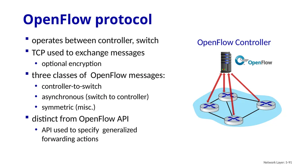
slide91. OpenFlow protocol Network Layer: 5-91 operates between controller, switch
TCP used to exchange messages
optional encryption
three classes of OpenFlow messages:
controller-to-switch
asynchronous (switch to controller)
symmetric (misc.)
distinct from OpenFlow API
API used to specify generalized forwarding actions<br>
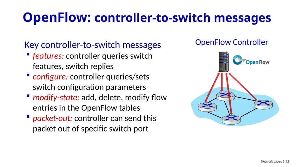
slide92. OpenFlow: controller-to-switch messages Network Layer: 5-92 Key controller-to-switch messages
features: controller queries switch features, switch replies
configure: controller queries/sets switch configuration parameters
modify-state: add, delete, modify flow entries in the OpenFlow tables
packet-out: controller can send this packet out of specific switch port<br>
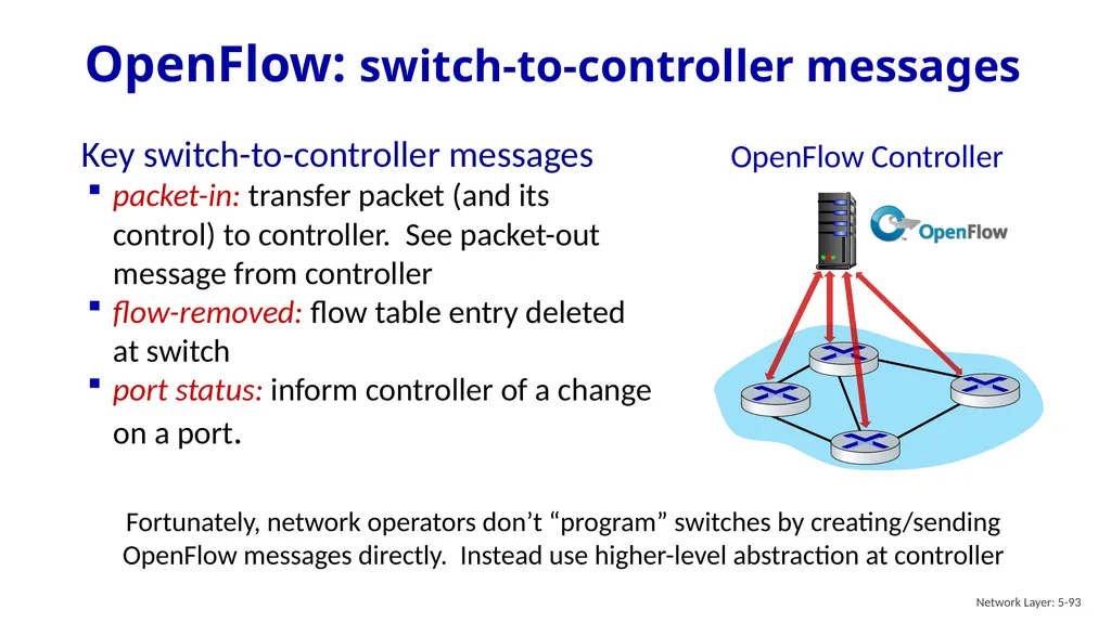
slide93. OpenFlow: switch-to-controller messages Network Layer: 5-93 Key switch-to-controller messages
packet-in: transfer packet (and its control) to controller. See packet-out message from controller
flow-removed: flow table entry deleted at switch
port status: inform controller of a change on a port. Fortunately, network operators don’t “program” switches by creating/sending OpenFlow messages directly. Instead use higher-level abstraction at controller<br>
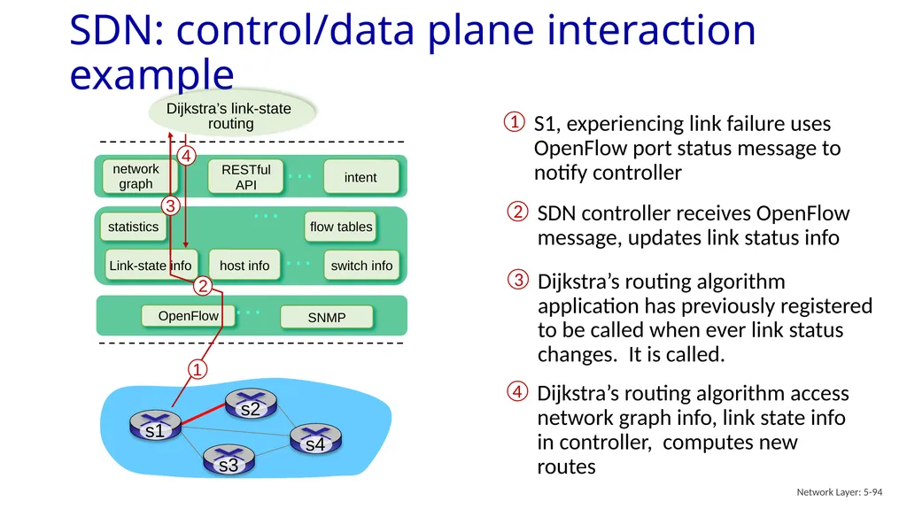
slide94. SDN: control/data plane interaction example Network Layer: 5-94 … … … … Dijkstra’s link-state
routing<br>
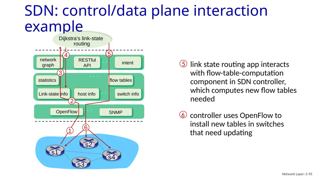
slide95. SDN: control/data plane interaction example Network Layer: 5-95 … … … … Dijkstra’s link-state
routing<br>
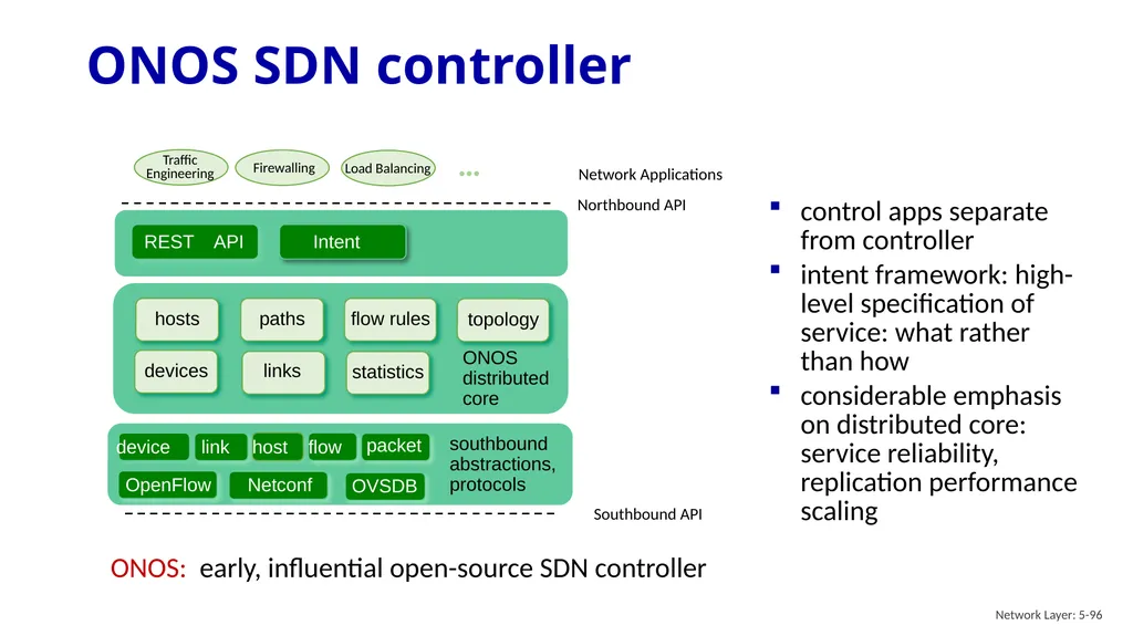
slide96. ONOS SDN controller Network Layer: 5-96 Network Applications Southbound API Northbound API … northbound abstractions,
protocols control apps separate from controller
intent framework: high-level specification of service: what rather than how
considerable emphasis on distributed core: service reliability, replication performance scaling ONOS: early, influential open-source SDN controller<br>
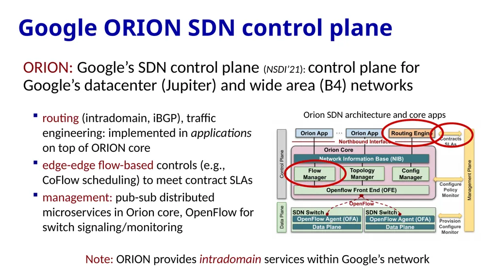
slide97. Google ORION SDN control plane ORION: Google’s SDN control plane (NSDI’21): control plane for Google’s datacenter (Jupiter) and wide area (B4) networks Orion SDN architecture and core apps routing (intradomain, iBGP), traffic engineering: implemented in applications on top of ORION core
edge-edge flow-based controls (e.g., CoFlow scheduling) to meet contract SLAs
management: pub-sub distributed microservices in Orion core, OpenFlow for switch signaling/monitoring Note: ORION provides intradomain services within Google’s network<br>
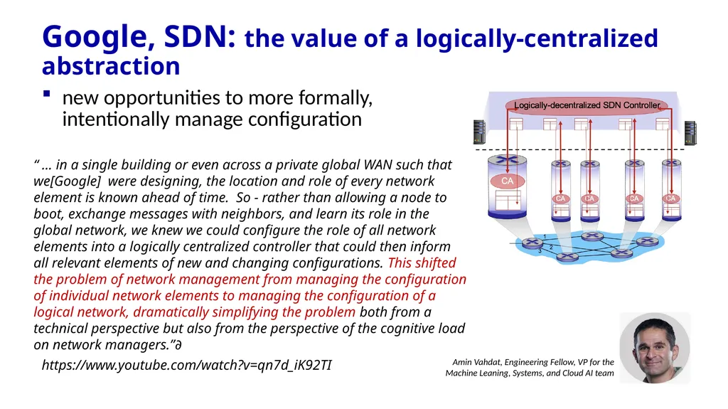
slide98. Google, SDN: the value of a logically-centralized abstraction new opportunities to more formally, intentionally manage configuration<br>
slide99. hardening the control plane: dependable, reliable, performance-scalable, secure distributed system
robustness to failures: leverage strong theory of reliable distributed system for control plane
dependability, security: “baked in” from day one?
networks, protocols meeting mission-specific requirements
e.g., real-time, ultra-reliable, ultra-secure
Internet-scaling: beyond a single AS
SDN critical in 5G cellular networks SDN: selected challenges Network Layer: 5-99<br>
slide100. SDN-computed versus router-computer forwarding tables:
just one example of logically-centralized-computed versus protocol computed
one could imagine SDN-computed congestion control:
controller sets sender rates based on router-reported (to controller) congestion levels SDN and the future of traditional network protocols Network Layer: 5-100<br>
slide101. Network layer: “control plane” roadmap network management, configuration
SNMP
NETCONF/YANG introduction
routing protocols
intra-ISP routing: OSPF
routing among ISPs: BGP
SDN control plane
Internet Control Message Protocol Network Layer: 5-101<br>
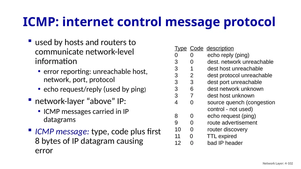
slide102. ICMP: internet control message protocol Network Layer: 4-102 used by hosts and routers to communicate network-level information
error reporting: unreachable host, network, port, protocol
echo request/reply (used by ping)
network-layer “above” IP:
ICMP messages carried in IP datagrams
ICMP message: type, code plus first 8 bytes of IP datagram causing error Type Code description
0 0 echo reply (ping)
3 0 dest. network unreachable
3 1 dest host unreachable
3 2 dest protocol unreachable
3 3 dest port unreachable
3 6 dest network unknown
3 7 dest host unknown
4 0 source quench (congestion
control - not used)
8 0 echo request (ping)
9 0 route advertisement
10 0 router discovery
11 0 TTL expired
12 0 bad IP header<br>
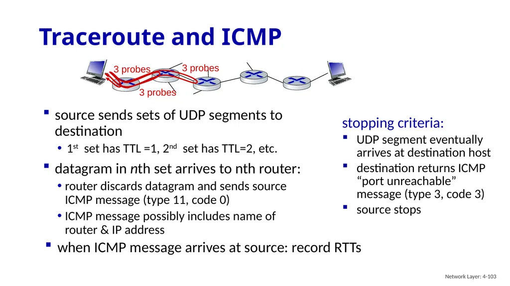
slide103. Traceroute and ICMP Network Layer: 4-103 when ICMP message arrives at source: record RTTs stopping criteria:
UDP segment eventually arrives at destination host
destination returns ICMP “port unreachable” message (type 3, code 3)
source stops 3 probes 3 probes 3 probes source sends sets of UDP segments to destination
1st set has TTL =1, 2nd set has TTL=2, etc.
datagram in nth set arrives to nth router:
router discards datagram and sends source ICMP message (type 11, code 0)
ICMP message possibly includes name of router & IP address<br>
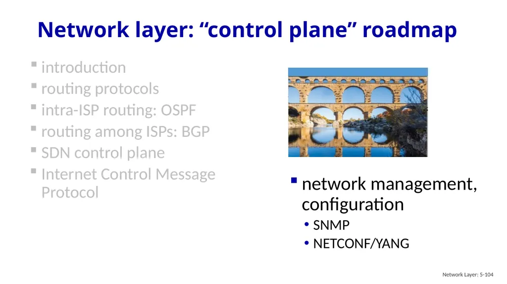
slide104. Network layer: “control plane” roadmap network management, configuration
SNMP
NETCONF/YANG introduction
routing protocols
intra-ISP routing: OSPF
routing among ISPs: BGP
SDN control plane
Internet Control Message Protocol Network Layer: 5-104<br>
slide105. autonomous systems (aka “network”): 1000s of interacting hardware/software components
other complex systems requiring monitoring, configuration, control:
jet airplane, nuclear power plant, others? What is network management? Network Layer: 5-105<br>
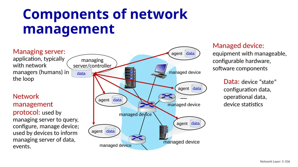
slide106. Components of network management Network Layer: 5-106 Managing server: application, typically with network
managers (humans) in the loop Managed device: equipment with manageable, configurable hardware, software components Data: device “state” configuration data, operational data, device statistics<br>
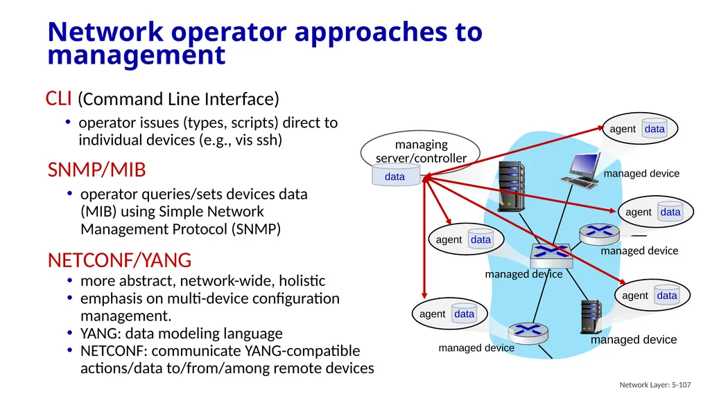
slide107. Network operator approaches to management Network Layer: 5-107 CLI (Command Line Interface)
operator issues (types, scripts) direct to individual devices (e.g., vis ssh) SNMP/MIB
operator queries/sets devices data (MIB) using Simple Network Management Protocol (SNMP) NETCONF/YANG
more abstract, network-wide, holistic
emphasis on multi-device configuration management.
YANG: data modeling language
NETCONF: communicate YANG-compatible actions/data to/from/among remote devices<br>
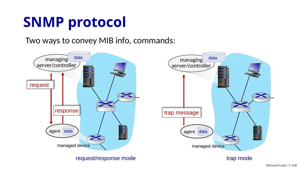
slide108. SNMP protocol Network Layer: 5-108 Two ways to convey MIB info, commands: request/response mode<br>
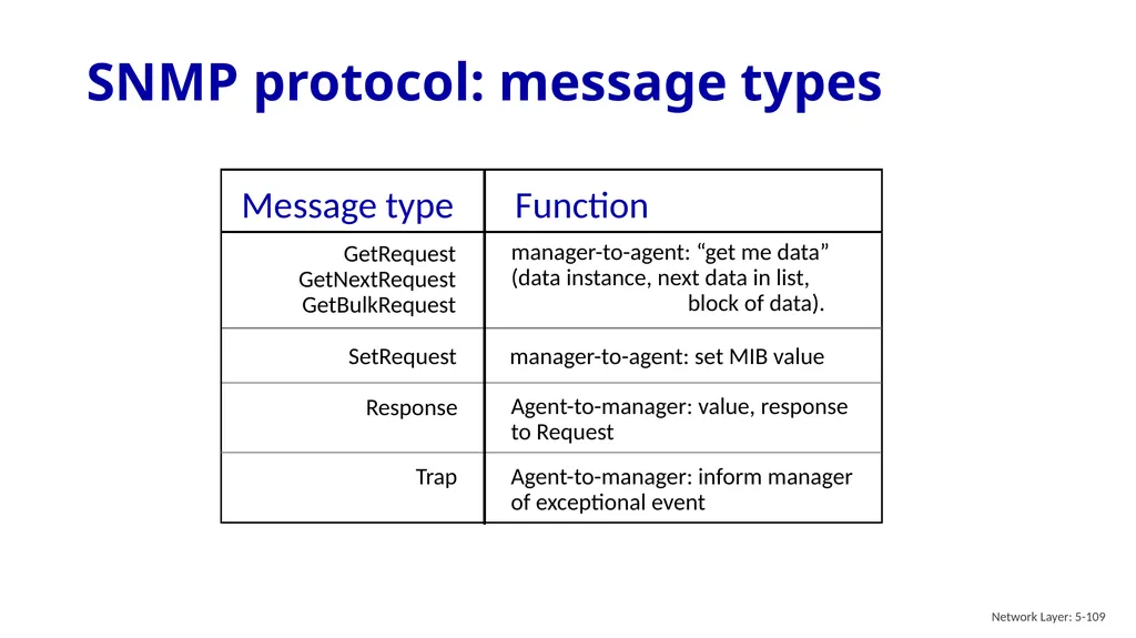
slide109. SNMP protocol: message types Network Layer: 5-109<br>
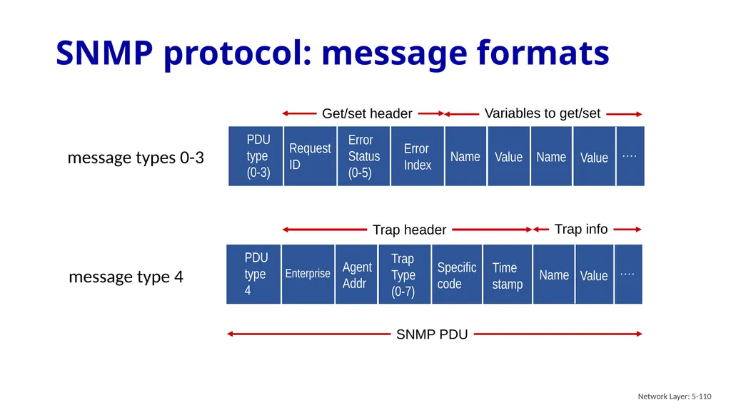
slide110. SNMP protocol: message formats Network Layer: 5-110 …. PDU
type
(0-3) Request
ID Error
Status
(0-5) Error
Index Name Value Name Value Get/set header Variables to get/set SNMP PDU message types 0-3<br>
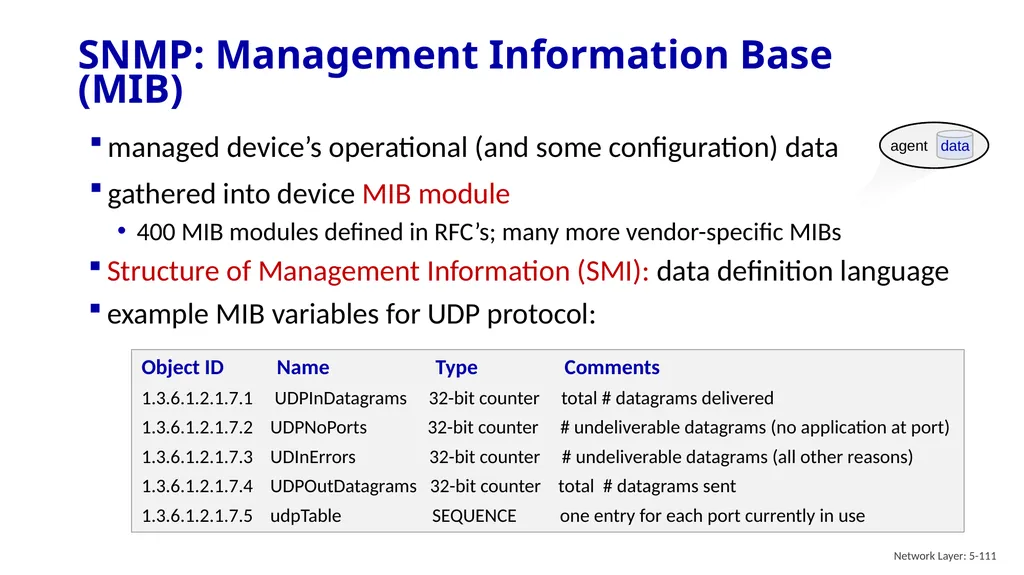
slide111. managed device’s operational (and some configuration) data
gathered into device MIB module
400 MIB modules defined in RFC’s; many more vendor-specific MIBs SNMP: Management Information Base (MIB) Network Layer: 5-111 Structure of Management Information (SMI): data definition language
example MIB variables for UDP protocol:<br>
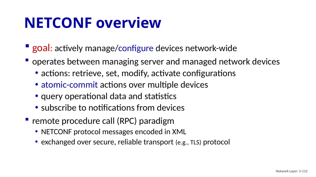
slide112. goal: actively manage/configure devices network-wide
operates between managing server and managed network devices
actions: retrieve, set, modify, activate configurations
atomic-commit actions over multiple devices
query operational data and statistics
subscribe to notifications from devices
remote procedure call (RPC) paradigm
NETCONF protocol messages encoded in XML
exchanged over secure, reliable transport (e.g., TLS) protocol NETCONF overview Network Layer: 5-112<br>
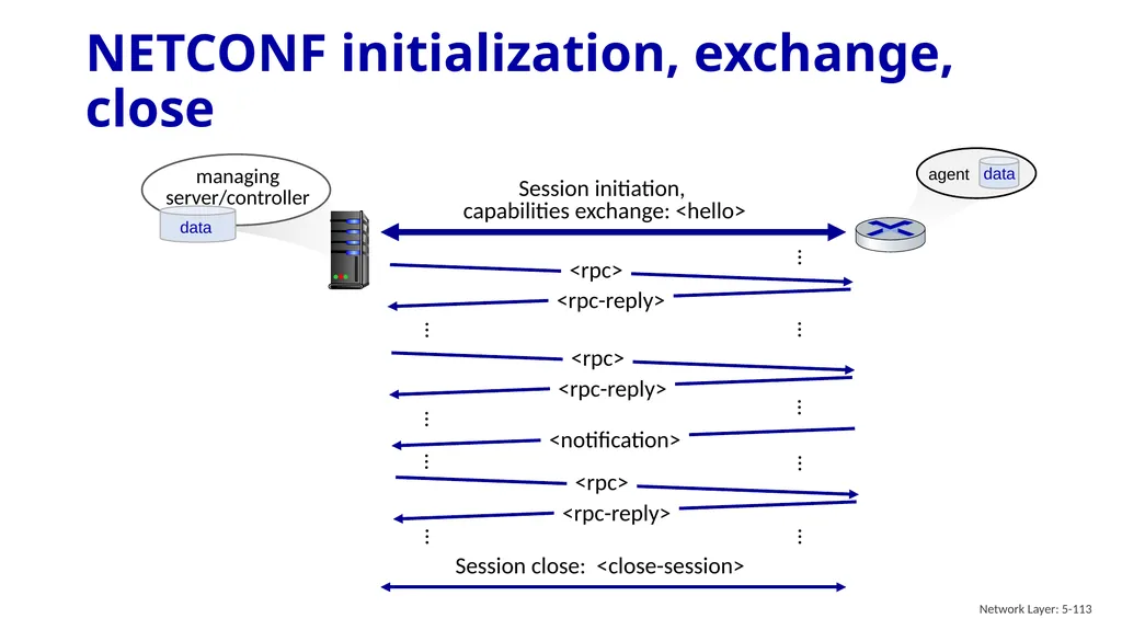
slide113. NETCONF initialization, exchange, close Network Layer: 5-113<br>
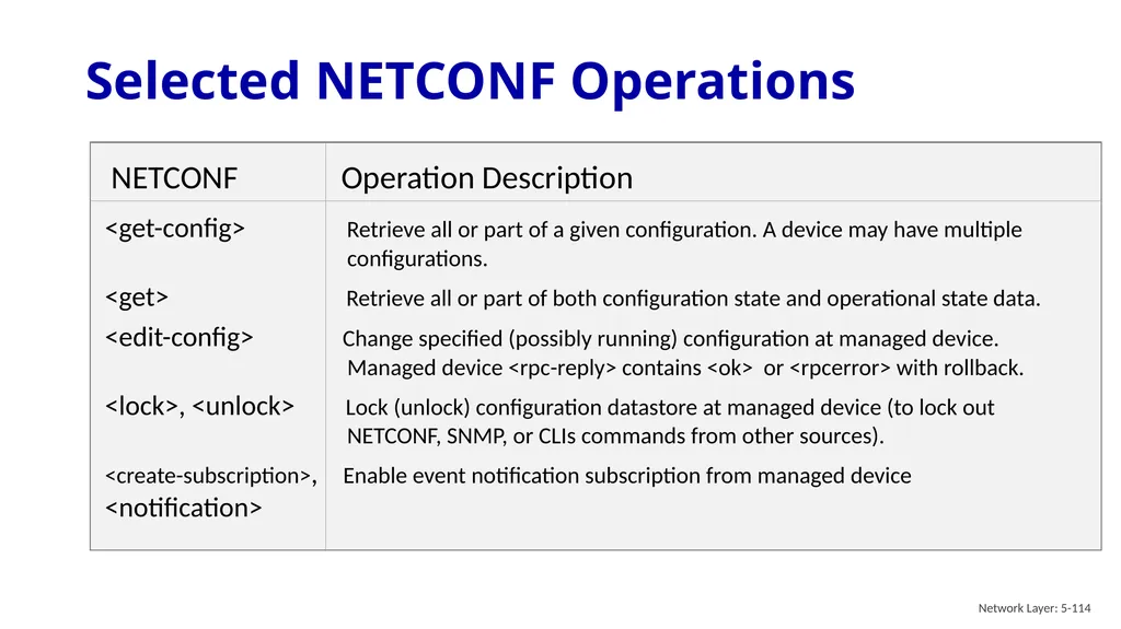
slide114. Selected NETCONF Operations Network Layer: 5-114 NETCONF Operation Description
<get-config> Retrieve all or part of a given configuration. A device may have multiple configurations.
<get> Retrieve all or part of both configuration state and operational state data.
<edit-config> Change specified (possibly running) configuration at managed device. Managed device <rpc-reply> contains <ok> or <rpcerror> with rollback.
<lock>, <unlock> Lock (unlock) configuration datastore at managed device (to lock out NETCONF, SNMP, or CLIs commands from other sources).
<create-subscription>, Enable event notification subscription from managed device
<notification><br>
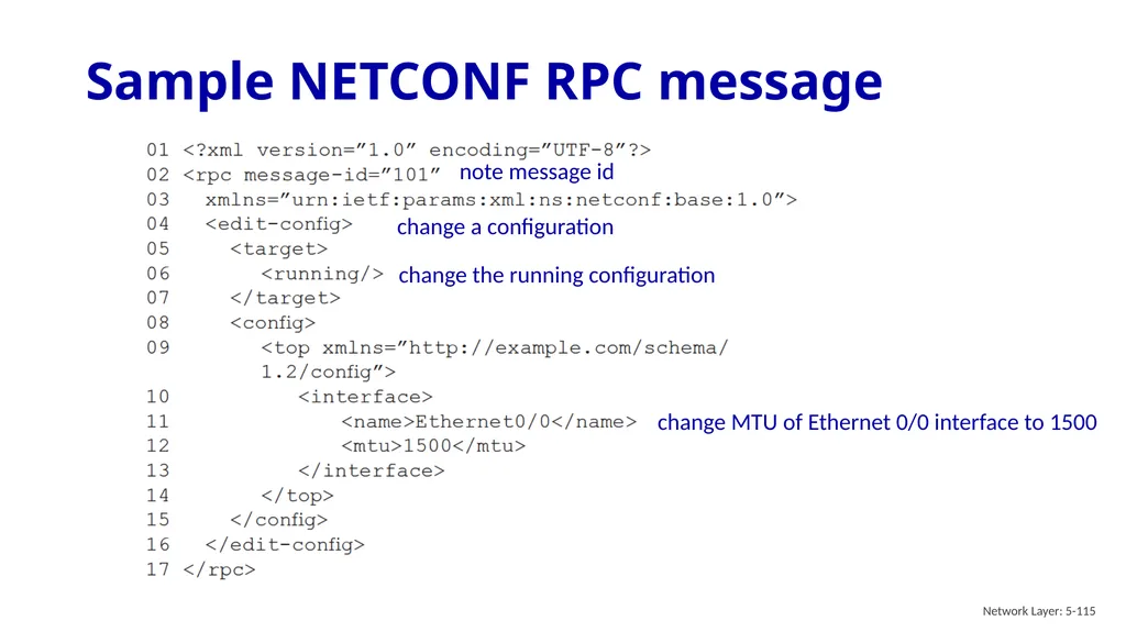
slide115. Sample NETCONF RPC message Network Layer: 5-115 note message id change the running configuration change MTU of Ethernet 0/0 interface to 1500 change a configuration<br>
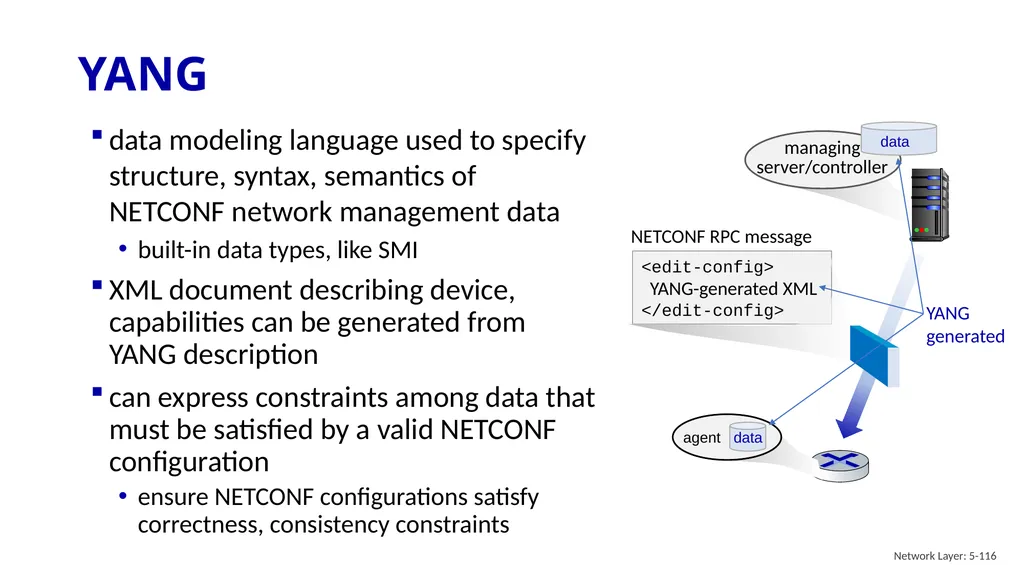
slide116. data modeling language used to specify structure, syntax, semantics of NETCONF network management data
built-in data types, like SMI
XML document describing device, capabilities can be generated from YANG description
can express constraints among data that must be satisfied by a valid NETCONF configuration
ensure NETCONF configurations satisfy correctness, consistency constraints YANG Network Layer: 5-116 NETCONF RPC message<br>
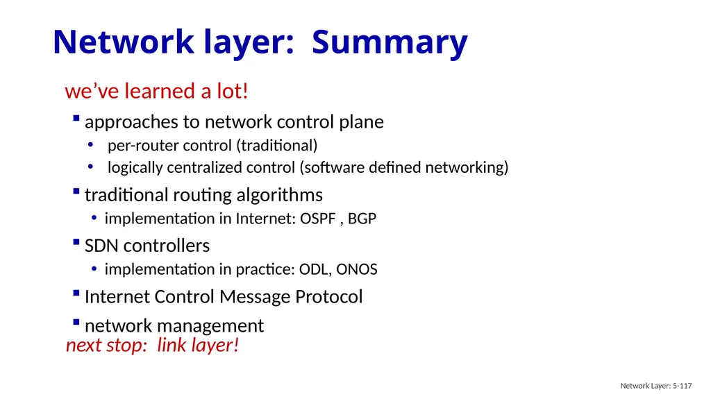
slide117. Network layer: Summary Network Layer: 5-117 we’ve learned a lot!
approaches to network control plane
per-router control (traditional)
logically centralized control (software defined networking)
traditional routing algorithms
implementation in Internet: OSPF , BGP
SDN controllers
implementation in practice: ODL, ONOS
Internet Control Message Protocol
network management next stop: link layer!<br>
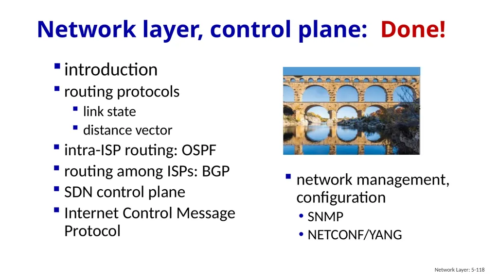
slide118. Network layer, control plane: Done! network management, configuration
SNMP
NETCONF/YANG introduction
routing protocols
link state
distance vector
intra-ISP routing: OSPF
routing among ISPs: BGP
SDN control plane
Internet Control Message Protocol Network Layer: 5-118<br>
slide119. Additional Chapter 5 slides Network Layer: 5-119<br>
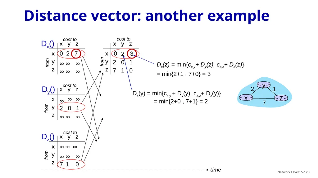
slide120. Distance vector: another example Network Layer: 5-120 x y z x y z 0 2 7 ∞ ∞ ∞ ∞ ∞ ∞ from cost to from from x y z x y z 0 x y z x y z ∞ ∞ ∞ ∞ ∞ cost to x y z x y z ∞ ∞ ∞ 7 1 0 cost to ∞
2 0 1 ∞ ∞ ∞ 2 0 1 7 1 0 time Dx() Dx(y) = min{cx,y + Dy(y), cx,z+ Dz(y)} = min{2+0 , 7+1} = 2 Dx(z) = min{cx,y+ Dy(z), cx,z+ Dz(z)}
= min{2+1 , 7+0} = 3 3 2 Dy() Dz() cost to from<br>
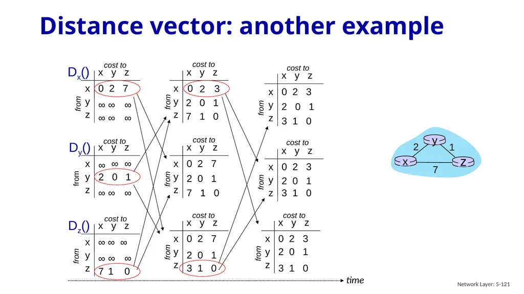
slide121. Distance vector: another example Network Layer: 5-121 x y z x y z 0 2 7 ∞ ∞ ∞ ∞ ∞ ∞ cost to from from x y z x y z ∞ ∞ ∞ ∞ ∞ cost to x y z x y z ∞ ∞ ∞ 7 1 0 cost to ∞
2 0 1 ∞ ∞ ∞ Dx() Dy() Dz() from time<br>
Control Plane A note on the use of these PowerPoint slides:
We’re making these slides freely available to all (faculty, students, readers). They’re in PowerPoint form so you see the animations; and can add, modify, and delete slides (including this one) and slide content to suit your needs. They obviously represent a lot of work on our part. In return for use, we only ask the following: If you use these slides (e.g., in a class) that you mention their source (after all, we’d like people to use our book!)
If you post any slides on a www site, that you note that they are adapted from (or perhaps identical to) our slides, and note our copyright of this material.
For a revision history, see the slide note for this page.
Thanks and enjoy! JFK/KWR
All material copyright 1996-2025
J.F Kurose and K.W. Ross, All Rights Reserved<br>
slide2. Network layer control plane: our goals understand principles behind network control plane:
traditional routing algorithms
SDN controllers
network management, configuration instantiation, implementation in the Internet:
OSPF, BGP
OpenFlow, ODL and ONOS controllers
Internet Control Message Protocol: ICMP
SNMP, YANG/NETCONF Network Layer: 5-2<br>
slide3. Network layer: “control plane” roadmap network management, configuration
SNMP
NETCONF/YANG introduction
routing protocols
link state
distance vector
intra-ISP routing: OSPF
routing among ISPs: BGP
SDN control plane
Internet Control Message Protocol Network Layer: 5-3<br>
slide4. Two approaches to structuring network control plane:
per-router control (traditional)
logically centralized control (software defined networking) Network-layer functions Network Layer: 5-4<br>
slide5. Per-router control plane Individual routing algorithm components in each and every router interact in the control plane 1 2 values in arriving
packet header 3 Network Layer: 5-5<br>
slide6. Software-Defined Networking (SDN) control plane Remote controller computes, installs forwarding tables in routers values in arriving
packet header Network Layer: 5-6<br>
slide7. Per-router control plane SDN control plane<br>
slide8. Network layer: “control plane” roadmap network management, configuration
SNMP
NETCONF/YANG introduction
routing protocols
link state
distance vector
intra-ISP routing: OSPF
routing among ISPs: BGP
SDN control plane
Internet Control Message Protocol Network Layer: 5-8<br>
slide9. Routing protocol goal: determine “good” paths (equivalently, routes), from sending hosts to receiving host, through network of routers
path: sequence of routers packets traverse from given initial source host to final destination host
“good”: least “cost”, “fastest”, “least congested”
routing: a “top-10” networking challenge! Routing protocols mobile network enterprise
network national or global ISP datacenter
network Network Layer: 5-9<br>
slide10. Graph abstraction: link costs Network Layer: 5-10 graph: G = (N,E) ca,b: cost of direct link connecting a and b
e.g., cw,z = 5, cu,z = ∞
cost defined by network operator: could always be 1, or inversely related to bandwidth, or inversely related to congestion N: set of routers = { u, v, w, x, y, z } E: set of links ={ (u,v), (u,x), (v,x), (v,w), (x,w), (x,y), (w,y), (w,z), (y,z) }<br>
slide11. Routing algorithm classification Network Layer: 5-11 global or decentralized information? How fast do routes change?<br>
slide12. Network layer: “control plane” roadmap network management, configuration
SNMP
NETCONF/YANG introduction
routing protocols
link state
distance vector
intra-ISP routing: OSPF
routing among ISPs: BGP
SDN control plane
Internet Control Message Protocol Network Layer: 5-12<br>
slide13. Dijkstra’s link-state routing algorithm Network Layer: 5-13 centralized: network topology, link costs known to all nodes
accomplished via “link state broadcast”
all nodes have same info
computes least cost paths from one node (“source”) to all other nodes
gives forwarding table for that node
iterative: after k iterations, know least cost path to k destinations<br>
slide14. Dijkstra’s link-state routing algorithm Network Layer: 5-14 1 Initialization:
2 N' = {u} /* compute least cost path from u to all other nodes */
3 for all nodes v
4 if v adjacent to u /* u initially knows direct-path-cost only to direct neighbors */
5 then D(v) = cu,v /* but may not be minimum cost! */
6 else D(v) = ∞
7 8 Loop
9
10
11
12
13
14
15 until all nodes in N' find w not in N' such that D(w) is a minimum
add w to N'
update D(v) for all v adjacent to w and not in N' :
D(v) = min ( D(v), D(w) + cw,v )
/* new least-path-cost to v is either old least-cost-path to v or known
least-cost-path to w plus direct-cost from w to v */<br>
slide15. Dijkstra’s algorithm: an example Step
0
1
2
3
4
5 N' D(v),p(v) D(x),p(x) D(y),p(y) D(z),p(z) D(w),p(w) D(w),p(w)
5,u
4,x
3,y
3,y u v w x y z Initialization (step 0):
For all a: if a adjacent to u then D(a) = cu,a<br>
slide16. Dijkstra’s algorithm: an example Step
0
1
2
3
4
5 N' D(v),p(v) D(x),p(x) D(y),p(y) D(z),p(z) D(w),p(w) D(w),p(w)
5,u
4,x
3,y
3,y u 8 Loop
9
10 find a not in N' such that D(a) is a minimum
add a to N' ux v w x y z<br>
slide17. Dijkstra’s algorithm: an example Step
0
1
2
3
4
5 N' D(v),p(v) D(x),p(x) D(y),p(y) D(z),p(z) D(w),p(w) D(w),p(w)
5,u
4,x
3,y
3,y u 8 Loop
9
10
11 find a not in N' such that D(a) is a minimum
add a to N' ux v w x y z update D(b) for all b adjacent to a and not in N' :
D(b) = min ( D(b), D(a) + ca,b )<br>
slide18. Dijkstra’s algorithm: an example Step
0
1
2
3
4
5 N' D(v),p(v) D(x),p(x) D(y),p(y) D(z),p(z) D(w),p(w) D(w),p(w)
5,u
4,x
3,y
3,y u 8 Loop
9
10 find a not in N' such that D(a) is a minimum
add a to N' ux v w x y z ∞ 2,x 4,x 2,u uxy<br>
slide19. Dijkstra’s algorithm: an example Step
0
1
2
3
4
5 N' D(v),p(v) D(x),p(x) D(y),p(y) D(z),p(z) D(w),p(w) u 8 Loop
9
10
11 find a not in N' such that D(a) is a minimum
add a to N' ux v w x y z uxy update D(b) for all b adjacent to a and not in N' :
D(b) = min ( D(b), D(a) + ca,b )<br>
slide20. Dijkstra’s algorithm: an example Step
0
1
2
3
4
5 N' D(v),p(v) D(x),p(x) D(y),p(y) D(z),p(z) D(w),p(w) u 8 Loop
9
10 find a not in N' such that D(a) is a minimum
add a to N' ux v w x y z uxy uxyv<br>
slide21. update D(b) for all b adjacent to a and not in N' :
D(b) = min ( D(b), D(a) + ca,b ) Dijkstra’s algorithm: an example Step
0
1
2
3
4
5 N' D(v),p(v) D(x),p(x) D(y),p(y) D(z),p(z) D(w),p(w) u 8 Loop
9
10
11 find a not in N' such that D(a) is a minimum
add a to N' ux v w x y z uxy uxyv<br>
slide22. Dijkstra’s algorithm: an example Step
0
1
2
3
4
5 N' D(v),p(v) D(x),p(x) D(y),p(y) D(z),p(z) D(w),p(w) u 8 Loop
9
10 find a not in N' such that D(a) is a minimum
add a to N' ux v w x y z uxy uxyv uxyvw<br>
slide23. update D(b) for all b adjacent to a and not in N' :
D(b) = min ( D(b), D(a) + ca,b ) Dijkstra’s algorithm: an example Step
0
1
2
3
4
5 N' D(v),p(v) D(x),p(x) D(y),p(y) D(z),p(z) D(w),p(w) u 8 Loop
9
10
11 find a not in N' such that D(a) is a minimum
add a to N' ux v w x y z uxy uxyv uxyvw 4,y<br>
slide24. Dijkstra’s algorithm: an example Step
0
1
2
3
4
5 N' D(v),p(v) D(x),p(x) D(y),p(y) D(z),p(z) D(w),p(w) u 8 Loop
9
10 find a not in N' such that D(a) is a minimum
add a to N' ux v w x y z uxy uxyv uxyvw 4,y uxyvwz<br>
slide25. Dijkstra’s algorithm: an example Step
0
1
2
3
4
5 N' D(v),p(v) D(x),p(x) D(y),p(y) D(z),p(z) D(w),p(w) u 8 Loop
9
10
11 find a not in N' such that D(a) is a minimum
add a to N' ux v w x y z uxy uxyv uxyvw 4,y uxyvwz update D(b) for all b adjacent to a and not in N' :
D(b) = min ( D(b), D(a) + ca,b )<br>
slide26. Dijkstra’s algorithm: an example Network Layer: 5-26 Step
0
1
2
3
4
5 N' D(v),p(v) D(x),p(x) D(y),p(y) D(z),p(z) 4,y D(w),p(w) D(w),p(w)
5,u
4,x
3,y
3,y uxyvwz uxyvw uxyv uxy ux u v w x y z find a not in N' such that D(a) is a minimum
add a to N'
update D(b) for all b adjacent to a and not in N' :
D(b) = min ( D(b), D(a) + ca,b ) Initialization (step 0): For all a: if a adjacent to then D(a) = cu,a<br>
slide27. Dijkstra’s algorithm: an example Network Layer: 5-27 D(w),p(w)
5,u
4,x
3,y
3,y resulting least-cost-path tree from u:<br>
slide28. Dijkstra’s algorithm: another example Network Layer: 5-28 Step N' D(v),
p(v) 0 1 2 3 4 5 D(w),
p(w) D(x),
p(x) D(y),
p(y) D(z),
p(z) u uw uwx uwxv uwxvy 12,y notes:
construct least-cost-path tree by tracing predecessor nodes
ties can exist (can be broken arbitrarily) uwxvyz v w x y z<br>
slide29. Dijkstra’s algorithm: discussion Network Layer: 5-29 algorithm complexity: n nodes
each of n iteration: need to check all nodes, w, not in N
n(n+1)/2 comparisons: O(n2) complexity
more efficient implementations possible: O(nlogn) message complexity:
each router must broadcast its link state information to other n routers
efficient (and interesting!) broadcast algorithms: O(n) link crossings to disseminate a broadcast message from one source
each router’s message crosses O(n) links: overall message complexity: O(n2)<br>
slide30. Dijkstra’s algorithm: oscillations possible Network Layer: 5-30 when link costs depend on traffic volume, route oscillations possible 1 1+e e 0 0 0 initially sample scenario:
routing to destination a, traffic entering at d, c, e with rates 1, e (<1), 1
link costs are directional, and volume-dependent<br>
slide31. Network layer: “control plane” roadmap network management, configuration
SNMP
NETCONF/YANG introduction
routing protocols
link state
distance vector
intra-ISP routing: OSPF
routing among ISPs: BGP
SDN control plane
Internet Control Message Protocol Network Layer: 5-31<br>
slide32. Based on Bellman-Ford (BF) equation (dynamic programming): Distance vector algorithm Network Layer: 5-32<br>
slide33. Bellman-Ford Example Network Layer: 5-33 2 2 1 3 1 1 2 5 3 5 Suppose that u’s neighboring nodes, x,v,w, know that for destination z: = min {2 + 5,
1 + 3,
5 + 3} = 4<br>
slide34. Distance vector algorithm Network Layer: 5-34 key idea:
from time-to-time, each node sends its own distance vector estimate to neighbors under minor, natural conditions, the estimate Dx(y) converge to the actual least cost dx(y)<br>
slide35. Distance vector algorithm: Network Layer: 5-35 iterative, asynchronous: each local iteration caused by:
local link cost change
DV update message from neighbor wait for (change in local link cost or msg from neighbor) each node: distributed, self-stopping: each node notifies neighbors only when its DV changes
neighbors then notify their neighbors – only if necessary
no notification received, no actions taken!<br>
slide36. Distance vector: example Network Layer: 5-36 1 1 1 1 1 1 1 1 1 8 1 All nodes have distance estimates to nearest neighbors (only) All nodes send their local distance vector to their neighbors<br>
slide37. Distance vector example: iteration Network Layer: 5-37 All nodes:
receive distance vectors from neighbors
compute their new local distance vector
send their new local distance vector to neighbors 1 1 1 1 1 1 1 1 1 8 1<br>
slide38. Distance vector example: iteration Network Layer: 5-38 1 1 1 1 1 1 1 1 1 8 1 All nodes:
receive distance vectors from neighbors
compute their new local distance vector
send their new local distance vector to neighbors<br>
slide39. Distance vector example: iteration Network Layer: 5-39 1 1 1 1 1 1 1 1 1 8 1 All nodes:
receive distance vectors from neighbors
compute their new local distance vector
send their new local distance vector to neighbors<br>
slide40. Distance vector example: iteration Network Layer: 5-40 1 1 1 1 1 1 1 1 1 8 1 All nodes:
receive distance vectors from neighbors
compute their new local distance vector
send their new local distance vector to neighbors<br>
slide41. Distance vector example: iteration Network Layer: 5-41 1 1 1 1 1 1 1 8 1 2 1 All nodes:
receive distance vectors from neighbors
compute their new local distance vector
send their new local distance vector to neighbors<br>
slide42. Distance vector example: iteration Network Layer: 5-42 1 1 1 1 1 1 1 1 1 8 1 All nodes:
receive distance vectors from neighbors
compute their new local distance vector
send their new local distance vector to neighbors<br>
slide43. Distance vector example: iteration Network Layer: 5-43 …. and so on
Let’s next take a look at the iterative computations at nodes<br>
slide44. Distance vector example: computation Network Layer: 5-44 1 1 1 1 1 1 1 1 1 8 1 b receives DVs from a, c, e<br>
slide45. Distance vector example: computation Network Layer: 5-45 1 1 1 1 1 1 1 1 1 8 1 b receives DVs from a, c, e, computes: b Db(a) = min{cb,a+Da(a), cb,c +Dc(a), cb,e+De(a)} = min{8,∞,∞} = 8 Db(c) = min{cb,a+Da(c), cb,c +Dc(c), c b,e +De(c)} = min{∞,1,∞} = 1 Db(d) = min{cb,a+Da(d), cb,c +Dc(d), c b,e +De(d)} = min{9,2,∞} = 2 Db(f) = min{cb,a+Da(f), cb,c +Dc(f), c b,e +De(f)} = min{∞,∞,2} = 2 Db(i) = min{cb,a+Da(i), cb,c +Dc(i), c b,e+De(i)} = min{∞, ∞, ∞} = ∞ Db(h) = min{cb,a+Da(h), cb,c +Dc(h), c b,e+De(h)} = min{∞, ∞, 2} = 2 Db(e) = min{cb,a+Da(e), cb,c +Dc(e), c b,e +De(e)} = min{∞,∞,1} = 1 Db(g) = min{cb,a+Da(g), cb,c +Dc(g), c b,e+De(g)} = min{∞, ∞, ∞} = ∞<br>
slide46. Distance vector example: computation Network Layer: 5-46 1 1 1 1 1 1 1 1 1 8 1 c receives DVs from b<br>
slide47. Distance vector example: computation Network Layer: 5-47 1 1 8 1 c receives DVs from b computes: Dc(a) = min{cc,b+Db(a}} = 1 + 8 = 9 Dc(b) = min{cc,b+Db(b)} = 1 + 0 = 1 Dc(d) = min{cc,b+Db(d)} = 1+ ∞ = ∞ Dc(e) = min{cc,b+Db(e)} = 1 + 1 = 2 Dc(f) = min{cc,b+Db(f)} = 1+ ∞ = ∞ Dc(g) = min{cc,b+Db(g)} = 1+ ∞ = ∞ Dc(i) = min{cc,b+Db(i)} = 1+ ∞ = ∞ Dc(h) = min{cbc,b+Db(h)} = 1+ ∞ = ∞ * Check out the online interactive exercises for more examples: http://gaia.cs.umass.edu/kurose_ross/interactive/<br>
slide48. Distance vector example: computation Network Layer: 5-48 1 1 1 1 1 1 1 1 1 8 1 e receives DVs from b, d, f, h Q: what is new DV computed in e at t=1?<br>
slide49. Distance vector: state information diffusion Iterative communication, computation steps diffuses information through network:<br>
slide50. Distance vector: link cost changes “good news
travels fast” t0 : y detects link-cost change, updates its DV, informs its neighbors. t1 : z receives update from y, updates its DV, computes new least cost to x , sends its neighbors its DV. t2 : y receives z’s update, updates its DV. y’s least costs do not change, so y does not send a message to z. link cost changes:
node detects local link cost change
updates routing info, recalculates local DV
if DV changes, notify neighbors<br>
slide51. Distance vector: link cost changes link cost changes:
node detects local link cost change
“bad news travels slow” – count-to-infinity problem: y sees direct link to x has new cost 60, but z has said it has a path at cost of 5. So y computes “my new cost to x will be 6, via z); notifies z of new cost of 6 to x. z learns that path to x via y has new cost 6, so z computes “my new cost to x will be 7 via y), notifies y of new cost of 7 to x. y learns that path to x via z has new cost 7, so y computes “my new cost to x will be 8 via y), notifies z of new cost of 8 to x. z learns that path to x via y has new cost 8, so z computes “my new cost to x will be 9 via y), notifies y of new cost of 9 to x. … see text for solutions. Distributed algorithms are tricky!<br>
slide52. Comparison of LS and DV algorithms message complexity
LS: n routers, O(n2) messages sent
DV: exchange between neighbors; convergence time varies speed of convergence
LS: O(n2) algorithm, O(n2) messages
may have oscillations
DV: convergence time varies
may have routing loops
count-to-infinity problem robustness: what happens if router malfunctions, or is compromised?
LS:
router can advertise incorrect link cost
each router computes only its own table
DV:
DV router can advertise incorrect path cost (“I have a really low-cost path to everywhere”): black-holing
each router’s DV is used by others: error propagate thru network<br>
slide53. Network layer: “control plane” roadmap network management, configuration
SNMP
NETCONF/YANG introduction
routing protocols
intra-ISP routing: OSPF
routing among ISPs: BGP
SDN control plane
Internet Control Message Protocol Network Layer: 5-53<br>
slide54. our routing study thus far - idealized
all routers identical
network “flat”
… not true in practice Making routing scalable Network Layer: 5-54 scale: billions of destinations:
can’t store all destinations in routing tables!
routing table exchange would swamp links! administrative autonomy:
Internet: a network of networks
each network admin may want to control routing in its own network<br>
slide55. aggregate routers into regions known as “autonomous systems” (AS) (a.k.a. “domains”) Internet approach to scalable routing Network Layer: 5-55 intra-AS (aka “intra-domain”): routing among routers within same AS (“network”)
all routers in AS must run same intra-domain protocol
routers in different AS can run different intra-domain routing protocols
gateway router: at “edge” of its own AS, has link(s) to router(s) in other AS’es inter-AS (aka “inter-domain”): routing among AS’es
gateways perform inter-domain routing (as well as intra-domain routing)<br>
slide56. Interconnected ASes Network Layer: 5-56 3b 3a 2a AS3 AS1 AS2 1a forwarding table configured by intra- and inter-AS routing algorithms intra-AS routing determine entries for destinations within AS inter-AS & intra-AS determine entries for external destinations<br>
slide57. Inter-AS routing: a role in intradomain forwarding Network Layer: 5-57 3b 3a 2a AS3 AS1 AS2 1a other
networks other
networks suppose router in AS1 receives datagram destined outside of AS1: AS1 inter-domain routing must:
learn which destinations reachable through AS2, which through AS3
propagate this reachability info to all routers in AS1 router should forward packet to gateway router in AS1, but which one?<br>
slide58. Intra-AS routing: routing within an AS Network Layer: 5-58 most common intra-AS routing protocols:
RIP: Routing Information Protocol [RFC 1723]
classic DV: DVs exchanged every 30 secs
no longer widely used
EIGRP: Enhanced Interior Gateway Routing Protocol
DV based
formerly Cisco-proprietary for decades (became open in 2013 [RFC 7868])
OSPF: Open Shortest Path First [RFC 2328]
link-state routing
IS-IS protocol (ISO standard, not RFC standard) essentially same as OSPF<br>
slide59. OSPF (Open Shortest Path First) routing Network Layer: 5-59 “open”: publicly available
classic link-state
each router floods OSPF link-state advertisements (directly over IP rather than using TCP/UDP) to all other routers in entire AS
multiple link costs metrics possible: bandwidth, delay
each router has full topology, uses Dijkstra’s algorithm to compute forwarding table
security: all OSPF messages authenticated (to prevent malicious intrusion)<br>
slide60. Hierarchical OSPF Network Layer: 5-60 two-level hierarchy: local area, backbone.
link-state advertisements flooded only in area, or backbone
each node has detailed area topology; only knows direction to reach other destinations area 1 area 2 area 3 backbone internal
routers<br>
slide61. Network layer: “control plane” roadmap network management, configuration
SNMP
NETCONF/YANG introduction
routing protocols
intra-ISP routing: OSPF
routing among ISPs: BGP
SDN control plane
Internet Control Message Protocol Network Layer: 5-61<br>
slide62. Interconnected ASes 3b 3a 2a AS3 AS1 AS2 1a Network Layer Control Plane: 5-62<br>
slide63. BGP (Border Gateway Protocol): the de facto inter-domain routing protocol
“glue that holds the Internet together”
allows subnet to advertise its existence, and the destinations it can reach, to rest of Internet: “I am here, here is who I can reach, and how”
BGP provides each AS a means to:
obtain destination network reachability info from neighboring ASes (eBGP)
determine routes to other networks based on reachability information and policy
propagate reachability information to all AS-internal routers (iBGP)
advertise (to neighboring networks) destination reachability info Internet inter-AS routing: BGP Network Layer Control Plane: 5-63<br>
slide64. eBGP, iBGP connections Network Layer: 5-64 AS 2 AS 3 AS 1<br>
slide65. BGP basics Network Layer: 5-65 when AS3 gateway 3a advertises path AS3,X to AS2 gateway 2c:
AS3 promises to AS2 it will forward datagrams towards X BGP session: two BGP routers (“peers”) exchange BGP messages over semi-permanent TCP connection:
advertising paths to different destination network prefixes (BGP is a “path vector” protocol)<br>
slide66. BGP protocol messages BGP messages exchanged between peers over TCP connection
BGP messages [RFC 4371]:
OPEN: opens TCP connection to remote BGP peer and authenticates sending BGP peer
UPDATE: advertises new path (or withdraws old)
KEEPALIVE: keeps connection alive in absence of UPDATES; also ACKs OPEN request
NOTIFICATION: reports errors in previous msg; also used to close connection<br>
slide67. Path attributes and BGP routes Network Layer: 5-67 BGP advertised route: prefix + attributes
prefix: destination being advertised
two important attributes:
AS-PATH: list of ASes through which prefix advertisement has passed
NEXT-HOP: indicates specific internal-AS router to next-hop AS
policy-based routing:
gateway receiving route advertisement uses import policy to accept/decline path (e.g., never route through AS Y).
AS policy also determines whether to advertise path to other other neighboring ASes<br>
slide68. BGP path advertisement Network Layer: 5-68 based on AS2 policy, AS2 router 2c accepts path AS3,X, propagates (via iBGP) to all AS2 routers AS2 router 2c receives path advertisement AS3,X (via eBGP) from AS3 router 3a based on AS2 policy, AS2 router 2a advertises (via eBGP) path AS2, AS3, X to AS1 router 1c<br>
slide69. Network Layer: 5-69 AS1 gateway router 1c learns path AS2,AS3,X from 2a gateway router may learn about multiple paths to destination: AS1 gateway router 1c learns path AS3,X from 3a based on policy, AS1 gateway router 1c chooses path AS3,X and advertises path within AS1 via iBGP BGP path advertisement: multiple paths<br>
slide70. BGP: populating forwarding tables recall: 1a, 1b, 1d learn via iBGP from 1c: “path to X goes through 1c” at 1d: OSPF intra-domain routing: to get to 1c, use interface 1 local link interfaces
at 1a, 1d at 1d: to get to X, use interface 1<br>
slide71. BGP: populating forwarding tables recall: 1a, 1b, 1d learn via iBGP from 1c: “path to X goes through 1c” at 1d: OSPF intra-domain routing: to get to 1c, use interface 1 at 1d: to get to X, use interface 1 at 1a: OSPF intra-domain routing: to get to 1c, use interface 2 at 1a: to get to X, use interface 2<br>
slide72. Hot potato routing Network Layer: 5-72 2d learns (via iBGP) it can route to X via 2a or 2c
hot potato routing: choose local gateway that has least intra-domain cost (e.g., 2d chooses 2a, even though more AS hops to X): don’t worry about inter-domain cost! OSPF link weights 201 112 263<br>
slide73. BGP: achieving policy via advertisements Network Layer: 5-73 A advertises path Aw to B and to C
B chooses not to advertise BAw to C!
B gets no “revenue” for routing CBAw, since none of C, A, w are B’s customers
C does not learn about CBAw path
C will route CAw (not using B) to get to w ISP only wants to route traffic to/from its customer networks (does not want to carry transit traffic between other ISPs – a typical “real world” policy) w y<br>
slide74. BGP: achieving policy via advertisements (more) Network Layer: 5-74 ISP only wants to route traffic to/from its customer networks (does not want to carry transit traffic between other ISPs – a typical “real world” policy) w y A,B,C are provider networks
x,w,y are customer (of provider networks)
x is dual-homed: attached to two networks
policy to enforce: x does not want to route from B to C via x
.. so x will not advertise to B a route to C<br>
slide75. router may learn about more than one route to destination AS, selects route based on:
local preference value attribute: policy decision
shortest AS-PATH
closest NEXT-HOP router: hot potato routing
additional criteria BGP route selection Network Layer: 5-75<br>
slide76. Why different Intra-, Inter-AS routing ? Network Layer: 5-76 policy:
inter-AS: admin wants control over how its traffic routed, who routes through its network
intra-AS: single admin, so policy less of an issue
scale:
hierarchical routing saves table size, reduced update traffic
performance:
intra-AS: can focus on performance
inter-AS: policy dominates over performance<br>
slide77. Network layer: “control plane” roadmap network management, configuration
SNMP
NETCONF/YANG introduction
routing protocols
intra-ISP routing: OSPF
routing among ISPs: BGP
SDN control plane
Internet Control Message Protocol Network Layer: 5-77<br>
slide78. Internet network layer: historically implemented via distributed, per-router control approach:
monolithic router contains switching hardware, runs proprietary implementation of Internet standard protocols (IP, RIP, IS-IS, OSPF, BGP) in proprietary router OS (e.g., Cisco IOS)
different “middleboxes” for different network layer functions: firewalls, load balancers, NAT boxes, ..
~2005: renewed interest in rethinking network control plane Software defined networking (SDN) Network Layer: 5-78<br>
slide79. Per-router control plane Individual routing algorithm components in each and every router interact in the control plane to compute forwarding tables 1 2 values in arriving
packet header 3 Network Layer: 4-79<br>
slide80. Software-Defined Networking (SDN) control plane Remote controller computes, installs forwarding tables in routers values in arriving
packet header Network Layer: 4-80<br>
slide81. Why a logically centralized control plane?
easier network management: avoid router misconfigurations, greater flexibility of traffic flows
table-based forwarding (recall OpenFlow API) allows “programming” routers
centralized “programming” easier: compute tables centrally and distribute
distributed “programming” more difficult: compute tables as result of distributed algorithm (protocol) implemented in each-and-every router
open (non-proprietary) implementation of control plane
foster innovation: let 1000 flowers bloom Software defined networking (SDN) Network Layer: 5-81<br>
slide82. SDN analogy: mainframe to PC revolution Network Layer: 5-82 Vertically integrated
Closed, proprietary
Slow innovation
Small industry Specialized
Operating
System Specialized
Hardware Specialized
Applications Horizontal
Open interfaces
Rapid innovation
Huge industry * Slide courtesy: N. McKeown<br>
slide83. Traffic engineering: difficult with traditional routing Network Layer: 5-83 Q: what if network operator wants u-to-z traffic to flow along uvwz, rather than uxyz?
A: need to re-define link weights so traffic routing algorithm computes routes accordingly (or need a new routing algorithm)! link weights are only control “knobs”: not much control!<br>
slide84. Traffic engineering: difficult with traditional routing Network Layer: 5-84 Q: what if network operator wants to split u-to-z traffic along uvwz and uxyz (load balancing)?
A: can’t do it (or need a new routing algorithm)<br>
slide85. Traffic engineering: difficult with traditional routing Network Layer: 5-85 Q: what if w wants to route blue and red traffic differently from w to z?
A: can’t do it (with destination-based forwarding, and LS, DV routing) We learned in Chapter 4 that generalized forwarding and SDN can be used to achieve any routing desired<br>
slide86. Software defined networking (SDN) Network Layer: 5-86 3. control plane functions external to data-plane switches … routing access control load
balance<br>
slide87. Software defined networking (SDN) Network Layer: 5-87 Data-plane switches:
fast, simple, commodity switches implementing generalized data-plane forwarding (Section 4.4) in hardware
flow (forwarding) table computed, installed under controller supervision
API for table-based switch control (e.g., OpenFlow)
defines what is controllable, what is not
protocol for communicating with controller (e.g., OpenFlow)<br>
slide88. Software defined networking (SDN) Network Layer: 5-88 SDN controller (network OS):
maintain network state information
interacts with network control applications “above” via northbound API
interacts with network switches “below” via southbound API
implemented as distributed system for performance, scalability, fault-tolerance, robustness<br>
slide89. Software defined networking (SDN) Network Layer: 5-89 network-control apps:
“brains” of control: implement control functions using lower-level services, API provided by SDN controller
unbundled: can be provided by 3rd party: distinct from routing vendor, or SDN controller<br>
slide90. Components of SDN controller Network Layer: 5-90 Network-wide distributed, robust state management Communication to/from controlled devices … … … … Interface, abstractions for network control apps SDN
controller communication: communicate between SDN controller and controlled switches network-wide state management : state of networks links, switches, services: a distributed database interface layer to network control apps: abstractions API<br>
slide91. OpenFlow protocol Network Layer: 5-91 operates between controller, switch
TCP used to exchange messages
optional encryption
three classes of OpenFlow messages:
controller-to-switch
asynchronous (switch to controller)
symmetric (misc.)
distinct from OpenFlow API
API used to specify generalized forwarding actions<br>
slide92. OpenFlow: controller-to-switch messages Network Layer: 5-92 Key controller-to-switch messages
features: controller queries switch features, switch replies
configure: controller queries/sets switch configuration parameters
modify-state: add, delete, modify flow entries in the OpenFlow tables
packet-out: controller can send this packet out of specific switch port<br>
slide93. OpenFlow: switch-to-controller messages Network Layer: 5-93 Key switch-to-controller messages
packet-in: transfer packet (and its control) to controller. See packet-out message from controller
flow-removed: flow table entry deleted at switch
port status: inform controller of a change on a port. Fortunately, network operators don’t “program” switches by creating/sending OpenFlow messages directly. Instead use higher-level abstraction at controller<br>
slide94. SDN: control/data plane interaction example Network Layer: 5-94 … … … … Dijkstra’s link-state
routing<br>
slide95. SDN: control/data plane interaction example Network Layer: 5-95 … … … … Dijkstra’s link-state
routing<br>
slide96. ONOS SDN controller Network Layer: 5-96 Network Applications Southbound API Northbound API … northbound abstractions,
protocols control apps separate from controller
intent framework: high-level specification of service: what rather than how
considerable emphasis on distributed core: service reliability, replication performance scaling ONOS: early, influential open-source SDN controller<br>
slide97. Google ORION SDN control plane ORION: Google’s SDN control plane (NSDI’21): control plane for Google’s datacenter (Jupiter) and wide area (B4) networks Orion SDN architecture and core apps routing (intradomain, iBGP), traffic engineering: implemented in applications on top of ORION core
edge-edge flow-based controls (e.g., CoFlow scheduling) to meet contract SLAs
management: pub-sub distributed microservices in Orion core, OpenFlow for switch signaling/monitoring Note: ORION provides intradomain services within Google’s network<br>
slide98. Google, SDN: the value of a logically-centralized abstraction new opportunities to more formally, intentionally manage configuration<br>
slide99. hardening the control plane: dependable, reliable, performance-scalable, secure distributed system
robustness to failures: leverage strong theory of reliable distributed system for control plane
dependability, security: “baked in” from day one?
networks, protocols meeting mission-specific requirements
e.g., real-time, ultra-reliable, ultra-secure
Internet-scaling: beyond a single AS
SDN critical in 5G cellular networks SDN: selected challenges Network Layer: 5-99<br>
slide100. SDN-computed versus router-computer forwarding tables:
just one example of logically-centralized-computed versus protocol computed
one could imagine SDN-computed congestion control:
controller sets sender rates based on router-reported (to controller) congestion levels SDN and the future of traditional network protocols Network Layer: 5-100<br>
slide101. Network layer: “control plane” roadmap network management, configuration
SNMP
NETCONF/YANG introduction
routing protocols
intra-ISP routing: OSPF
routing among ISPs: BGP
SDN control plane
Internet Control Message Protocol Network Layer: 5-101<br>
slide102. ICMP: internet control message protocol Network Layer: 4-102 used by hosts and routers to communicate network-level information
error reporting: unreachable host, network, port, protocol
echo request/reply (used by ping)
network-layer “above” IP:
ICMP messages carried in IP datagrams
ICMP message: type, code plus first 8 bytes of IP datagram causing error Type Code description
0 0 echo reply (ping)
3 0 dest. network unreachable
3 1 dest host unreachable
3 2 dest protocol unreachable
3 3 dest port unreachable
3 6 dest network unknown
3 7 dest host unknown
4 0 source quench (congestion
control - not used)
8 0 echo request (ping)
9 0 route advertisement
10 0 router discovery
11 0 TTL expired
12 0 bad IP header<br>
slide103. Traceroute and ICMP Network Layer: 4-103 when ICMP message arrives at source: record RTTs stopping criteria:
UDP segment eventually arrives at destination host
destination returns ICMP “port unreachable” message (type 3, code 3)
source stops 3 probes 3 probes 3 probes source sends sets of UDP segments to destination
1st set has TTL =1, 2nd set has TTL=2, etc.
datagram in nth set arrives to nth router:
router discards datagram and sends source ICMP message (type 11, code 0)
ICMP message possibly includes name of router & IP address<br>
slide104. Network layer: “control plane” roadmap network management, configuration
SNMP
NETCONF/YANG introduction
routing protocols
intra-ISP routing: OSPF
routing among ISPs: BGP
SDN control plane
Internet Control Message Protocol Network Layer: 5-104<br>
slide105. autonomous systems (aka “network”): 1000s of interacting hardware/software components
other complex systems requiring monitoring, configuration, control:
jet airplane, nuclear power plant, others? What is network management? Network Layer: 5-105<br>
slide106. Components of network management Network Layer: 5-106 Managing server: application, typically with network
managers (humans) in the loop Managed device: equipment with manageable, configurable hardware, software components Data: device “state” configuration data, operational data, device statistics<br>
slide107. Network operator approaches to management Network Layer: 5-107 CLI (Command Line Interface)
operator issues (types, scripts) direct to individual devices (e.g., vis ssh) SNMP/MIB
operator queries/sets devices data (MIB) using Simple Network Management Protocol (SNMP) NETCONF/YANG
more abstract, network-wide, holistic
emphasis on multi-device configuration management.
YANG: data modeling language
NETCONF: communicate YANG-compatible actions/data to/from/among remote devices<br>
slide108. SNMP protocol Network Layer: 5-108 Two ways to convey MIB info, commands: request/response mode<br>
slide109. SNMP protocol: message types Network Layer: 5-109<br>
slide110. SNMP protocol: message formats Network Layer: 5-110 …. PDU
type
(0-3) Request
ID Error
Status
(0-5) Error
Index Name Value Name Value Get/set header Variables to get/set SNMP PDU message types 0-3<br>
slide111. managed device’s operational (and some configuration) data
gathered into device MIB module
400 MIB modules defined in RFC’s; many more vendor-specific MIBs SNMP: Management Information Base (MIB) Network Layer: 5-111 Structure of Management Information (SMI): data definition language
example MIB variables for UDP protocol:<br>
slide112. goal: actively manage/configure devices network-wide
operates between managing server and managed network devices
actions: retrieve, set, modify, activate configurations
atomic-commit actions over multiple devices
query operational data and statistics
subscribe to notifications from devices
remote procedure call (RPC) paradigm
NETCONF protocol messages encoded in XML
exchanged over secure, reliable transport (e.g., TLS) protocol NETCONF overview Network Layer: 5-112<br>
slide113. NETCONF initialization, exchange, close Network Layer: 5-113<br>
slide114. Selected NETCONF Operations Network Layer: 5-114 NETCONF Operation Description
<get-config> Retrieve all or part of a given configuration. A device may have multiple configurations.
<get> Retrieve all or part of both configuration state and operational state data.
<edit-config> Change specified (possibly running) configuration at managed device. Managed device <rpc-reply> contains <ok> or <rpcerror> with rollback.
<lock>, <unlock> Lock (unlock) configuration datastore at managed device (to lock out NETCONF, SNMP, or CLIs commands from other sources).
<create-subscription>, Enable event notification subscription from managed device
<notification><br>
slide115. Sample NETCONF RPC message Network Layer: 5-115 note message id change the running configuration change MTU of Ethernet 0/0 interface to 1500 change a configuration<br>
slide116. data modeling language used to specify structure, syntax, semantics of NETCONF network management data
built-in data types, like SMI
XML document describing device, capabilities can be generated from YANG description
can express constraints among data that must be satisfied by a valid NETCONF configuration
ensure NETCONF configurations satisfy correctness, consistency constraints YANG Network Layer: 5-116 NETCONF RPC message<br>
slide117. Network layer: Summary Network Layer: 5-117 we’ve learned a lot!
approaches to network control plane
per-router control (traditional)
logically centralized control (software defined networking)
traditional routing algorithms
implementation in Internet: OSPF , BGP
SDN controllers
implementation in practice: ODL, ONOS
Internet Control Message Protocol
network management next stop: link layer!<br>
slide118. Network layer, control plane: Done! network management, configuration
SNMP
NETCONF/YANG introduction
routing protocols
link state
distance vector
intra-ISP routing: OSPF
routing among ISPs: BGP
SDN control plane
Internet Control Message Protocol Network Layer: 5-118<br>
slide119. Additional Chapter 5 slides Network Layer: 5-119<br>
slide120. Distance vector: another example Network Layer: 5-120 x y z x y z 0 2 7 ∞ ∞ ∞ ∞ ∞ ∞ from cost to from from x y z x y z 0 x y z x y z ∞ ∞ ∞ ∞ ∞ cost to x y z x y z ∞ ∞ ∞ 7 1 0 cost to ∞
2 0 1 ∞ ∞ ∞ 2 0 1 7 1 0 time Dx() Dx(y) = min{cx,y + Dy(y), cx,z+ Dz(y)} = min{2+0 , 7+1} = 2 Dx(z) = min{cx,y+ Dy(z), cx,z+ Dz(z)}
= min{2+1 , 7+0} = 3 3 2 Dy() Dz() cost to from<br>
slide121. Distance vector: another example Network Layer: 5-121 x y z x y z 0 2 7 ∞ ∞ ∞ ∞ ∞ ∞ cost to from from x y z x y z ∞ ∞ ∞ ∞ ∞ cost to x y z x y z ∞ ∞ ∞ 7 1 0 cost to ∞
2 0 1 ∞ ∞ ∞ Dx() Dy() Dz() from time<br>