
CSMC 412 Operating Systems Prof. Ashok K Agrawala
Description: CSMC 412 Operating Systems Prof. Ashok K Agrawala Online Set 13 Distributed Systems 1 Overview A distributed system is a collection of loosely coupled nodes interconnected by a communications network Nodes variously called processors,
Related Topics
Download Presentation
"CSMC 412 Operating Systems Prof. Ashok K Agrawala" is the property of its rightful owner. Permission is granted to download and print the materials on this website for personal, non-commercial use only, and to display it on your personal computer provided you do not modify the materials and that you retain all copyright notices contained in the materials. By downloading content from our website, you accept the terms of this agreement.
Presentation Transcript
slide1. CSMC 412 Operating Systems
Prof. Ashok K Agrawala
Online Set 13
Distributed Systems 1<br>
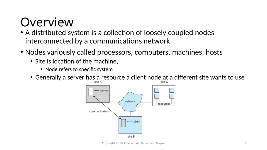
slide2. Overview A distributed system is a collection of loosely coupled nodes interconnected by a communications network
Nodes variously called processors, computers, machines, hosts
Site is location of the machine,
Node refers to specific system
Generally a server has a resource a client node at a different site wants to use Copyright 2018 Silberschatz, Galvin and Gagne 2<br>
slide3. Overview (cont.) Nodes may exist in a client-server, peer-to-peer, or hybrid configuration.
In client-server configuration, server has a resource that a client would like to use
In peer-to-peer configuration, each node shares equal responsibilities and can act as both clients and servers
Communication over a network occurs through message passing
All higher-level functions of a standalone system can be expanded to encompass a distributed system Copyright 2018 Silberschatz, Galvin and Gagne 3<br>
slide4. Reasons for Distributed Systems Resource sharing
Sharing files or printing at remote sites
Processing information in a distributed database
Using remote specialized hardware devices such as graphics processing units (GPUs)
Computation speedup
Distribute subcomputations among various sites to run concurrently
Load balancing – moving jobs to more lightly-loaded sites
Reliability
Detect and recover from site failure, function transfer, reintegrate failed site Copyright 2018 Silberschatz, Galvin and Gagne 4<br>
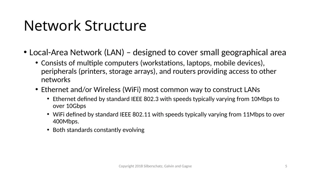
slide5. Network Structure Local-Area Network (LAN) – designed to cover small geographical area
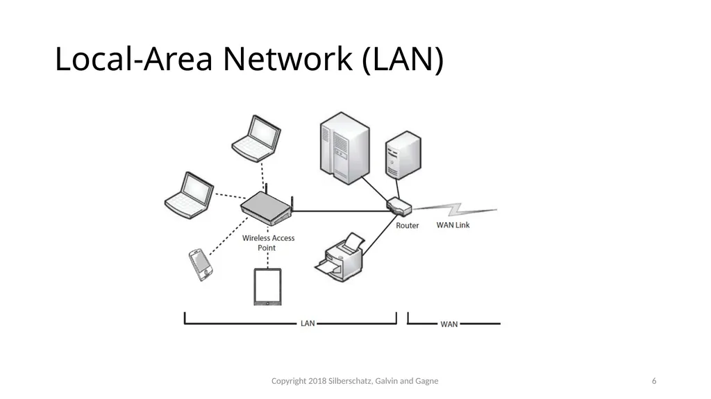
Consists of multiple computers (workstations, laptops, mobile devices), peripherals (printers, storage arrays), and routers providing access to other networks
Ethernet and/or Wireless (WiFi) most common way to construct LANs
Ethernet defined by standard IEEE 802.3 with speeds typically varying from 10Mbps to over 10Gbps
WiFi defined by standard IEEE 802.11 with speeds typically varying from 11Mbps to over 400Mbps.
Both standards constantly evolving Copyright 2018 Silberschatz, Galvin and Gagne 5<br>
slide6. Local-Area Network (LAN) Copyright 2018 Silberschatz, Galvin and Gagne 6<br>
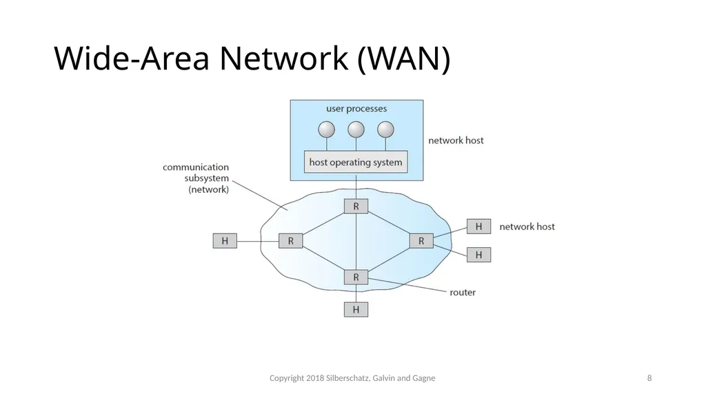
slide7. Network Structure (Cont.) Wide-Area Network (WAN) – links geographically separated sites
Point-to-point connections via links
Telephone lines, leased (dedicated data) lines, optical cable, microwave links, radio waves, and satellite channels
Implemented via routers to direct traffic from one network to another
Internet (World Wide Web) WAN enables hosts world wide to communicate
Speeds vary
Many backbone providers have speeds at 40-100Gbps
Local Internet Service Providers (ISPs) may be slower
WAN links constantly being upgraded
WANs and LANs interconnect, similar to cell phone network:
Cell phones use radio waves to cell towers
Towers connect to other towers and hubs Copyright 2018 Silberschatz, Galvin and Gagne 7<br>
slide8. Wide-Area Network (WAN) Copyright 2018 Silberschatz, Galvin and Gagne 8<br>
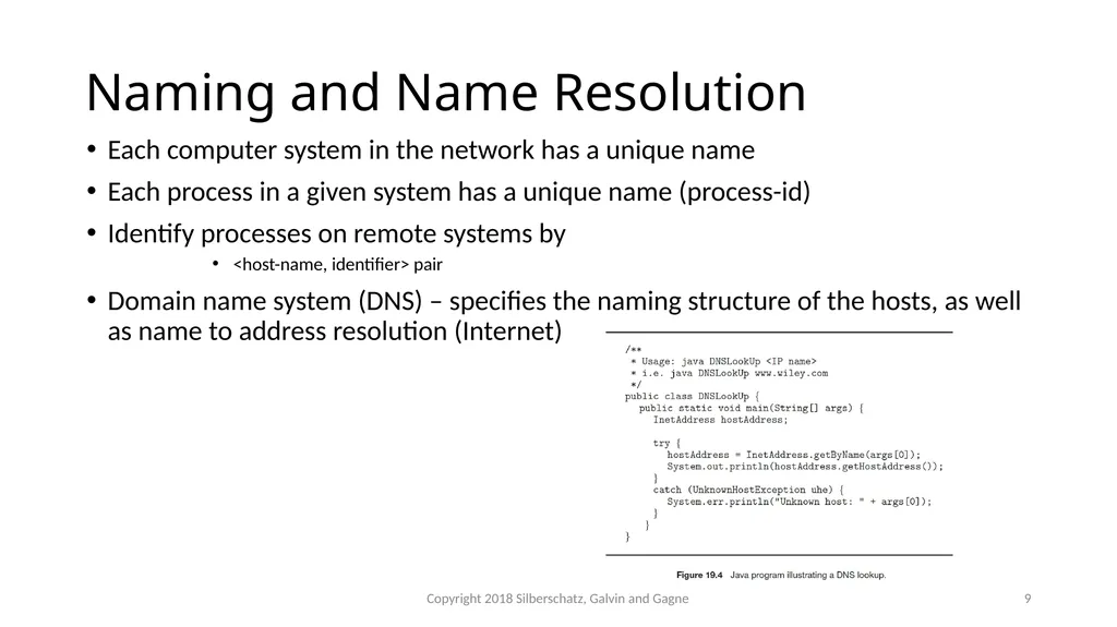
slide9. Naming and Name Resolution Each computer system in the network has a unique name
Each process in a given system has a unique name (process-id)
Identify processes on remote systems by
<host-name, identifier> pair
Domain name system (DNS) – specifies the naming structure of the hosts, as well as name to address resolution (Internet) Copyright 2018 Silberschatz, Galvin and Gagne 9<br>
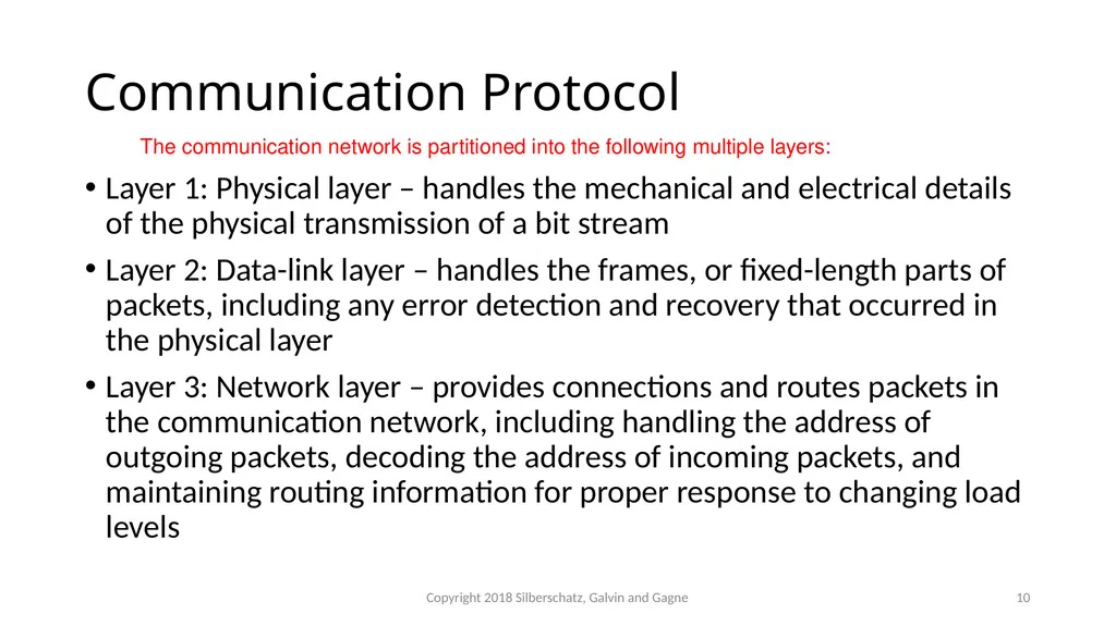
slide10. Communication Protocol Layer 1: Physical layer – handles the mechanical and electrical details of the physical transmission of a bit stream
Layer 2: Data-link layer – handles the frames, or fixed-length parts of packets, including any error detection and recovery that occurred in the physical layer
Layer 3: Network layer – provides connections and routes packets in the communication network, including handling the address of outgoing packets, decoding the address of incoming packets, and maintaining routing information for proper response to changing load levels The communication network is partitioned into the following multiple layers: Copyright 2018 Silberschatz, Galvin and Gagne 10<br>
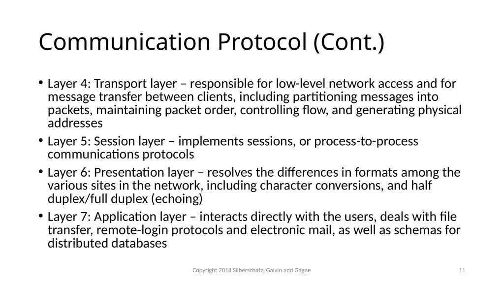
slide11. Communication Protocol (Cont.) Layer 4: Transport layer – responsible for low-level network access and for message transfer between clients, including partitioning messages into packets, maintaining packet order, controlling flow, and generating physical addresses
Layer 5: Session layer – implements sessions, or process-to-process communications protocols
Layer 6: Presentation layer – resolves the differences in formats among the various sites in the network, including character conversions, and half duplex/full duplex (echoing)
Layer 7: Application layer – interacts directly with the users, deals with file transfer, remote-login protocols and electronic mail, as well as schemas for distributed databases Copyright 2018 Silberschatz, Galvin and Gagne 11<br>
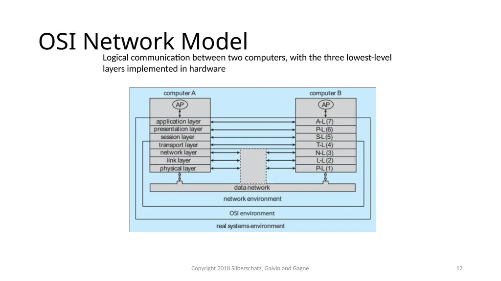
slide12. Logical communication between two computers, with the three lowest-level layers implemented in hardware OSI Network Model Copyright 2018 Silberschatz, Galvin and Gagne 12<br>
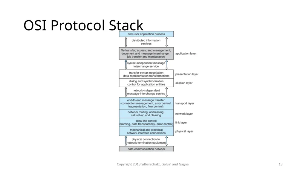
slide13. OSI Protocol Stack Copyright 2018 Silberschatz, Galvin and Gagne 13<br>
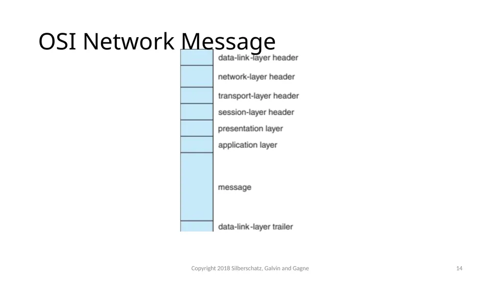
slide14. OSI Network Message Copyright 2018 Silberschatz, Galvin and Gagne 14<br>
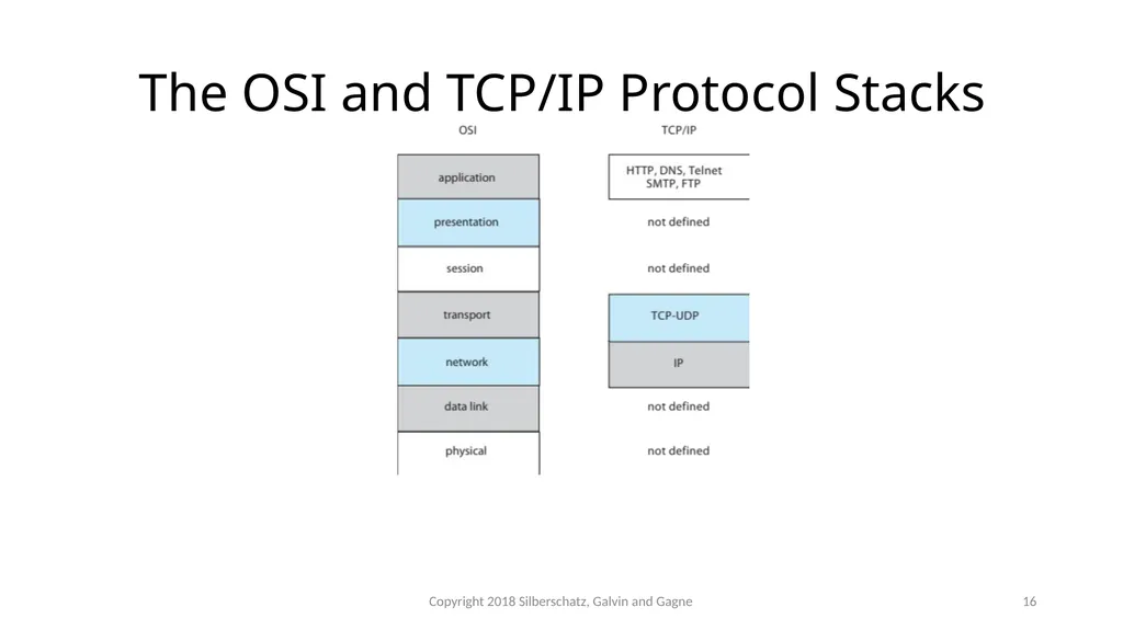
slide15. The OSI model The OSI model formalizes some of the earlier work done in network protocols but was developed in the late 1970s and is currently not in widespread use
The most widely adopted protocol stack is the TCP/IP model, which has been adopted by virtually all Internet sites
The TCP/IP protocol stack has fewer layers than the OSI model. Theoretically, because it combines several functions in each layer, it is more difficult to implement but more efficient than OSI networking
The relationship between the OSI and TCP/IP models is shown in the next slide Copyright 2018 Silberschatz, Galvin and Gagne 15<br>
slide16. The OSI and TCP/IP Protocol Stacks Copyright 2018 Silberschatz, Galvin and Gagne 16<br>
slide17. TCP/IP Example Every host has a name and an associated IP address (host-id)
Hierarchical and segmented
Sending system checks routing tables and locates a router to send packet
Router uses segmented network part of host-id to determine where to transfer packet
This may repeat among multiple routers
Destination system receives the packet
Packet may be complete message, or it may need to be reassembled into larger message spanning multiple packets Copyright 2018 Silberschatz, Galvin and Gagne 17<br>
slide18. TCP/IP Example (Cont.) Within a network, how does a packet move from sender (host or router) to receiver?
Every Ethernet/WiFi device has a medium access control (MAC) address
Two devices on same LAN communicate via MAC address
If a system needs to send data to another system, it needs to discover the IP to MAC address mapping
Uses address resolution protocol (ARP)
A broadcast uses a special network address to signal that all hosts should receive and process the packet
Not forwarded by routers to different networks Copyright 2018 Silberschatz, Galvin and Gagne 18<br>
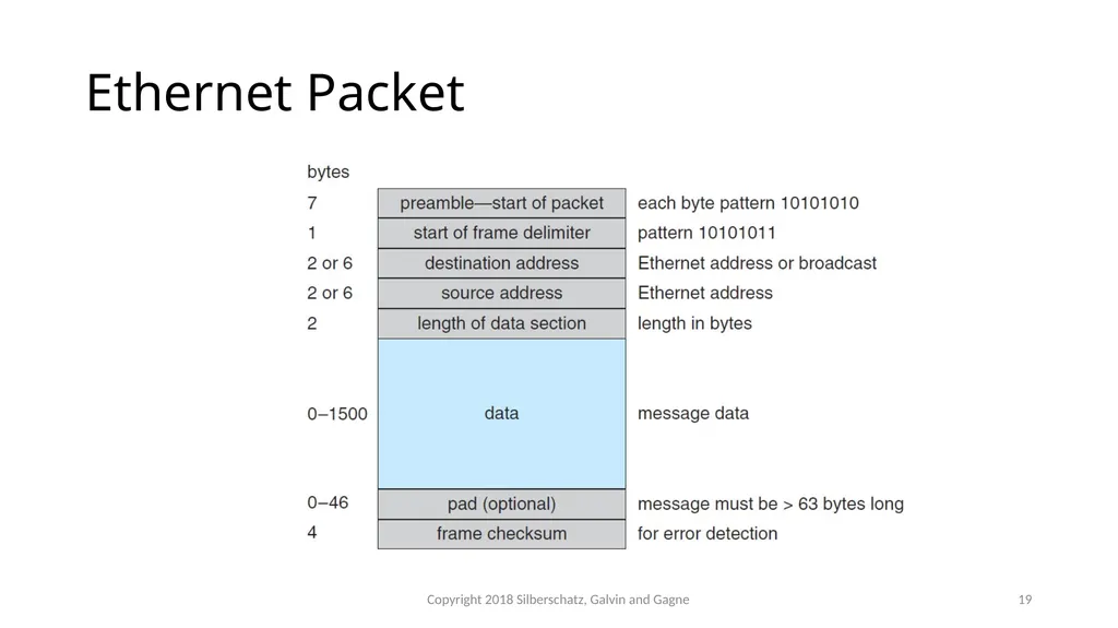
slide19. Ethernet Packet Copyright 2018 Silberschatz, Galvin and Gagne 19<br>
slide20. Transport Protocols UDP and TCP Once a host with a specific IP address receives a packet, it must somehow pass it to the correct waiting process
Transport protocols TCP and UDP identify receiving and sending processes through the use of a port number
Allows host with single IP address to have multiple server/client processes sending/receiving packets
Well-known port numbers are used for many services
FTP – port 21
ssh – port 22
SMTP – port 25
HTTP – port 80
Transport protocol can be simple or can add reliability to network packet stream Copyright 2018 Silberschatz, Galvin and Gagne 20<br>
slide21. User Datagram Protocol UDP is unreliable – bare-bones extension to IP with addition of port number
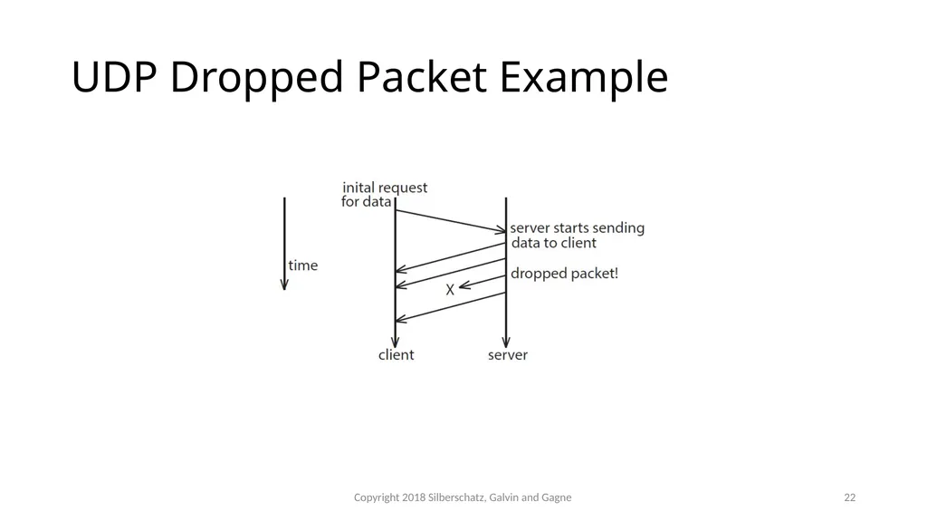
Since there are no guarantees of delivery in the lower network (IP) layer, packets may become lost
Packets may also be received out-out-order
UDP is also connectionless – no connection setup at the beginning of the transmission to set up state
Also no connection tear-down at the end of transmission
UDP packets are also called datagrams Copyright 2018 Silberschatz, Galvin and Gagne 21<br>
slide22. UDP Dropped Packet Example Copyright 2018 Silberschatz, Galvin and Gagne 22<br>
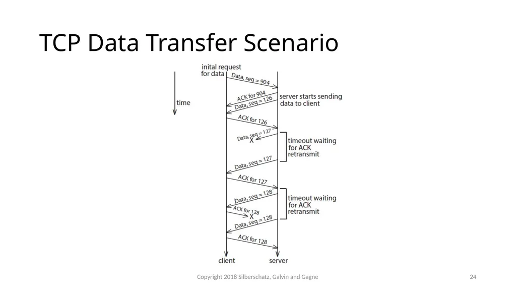
slide23. Transmission Control Protocol TCP is both reliable and connection-oriented
In addition to port number, TCP provides abstraction to allow in-order, uninterrupted byte-stream across an unreliable network
Whenever host sends packet, the receiver must send an acknowledgement packet (ACK). If ACK not received before a timer expires, sender will resend.
Sequence numbers in TCP header allow receiver to put packets in order and notice missing packets
Connections are initiated with series of control packets called a three-way handshake
Connections also closed with series of control packets Copyright 2018 Silberschatz, Galvin and Gagne 23<br>
slide24. TCP Data Transfer Scenario Copyright 2018 Silberschatz, Galvin and Gagne 24<br>
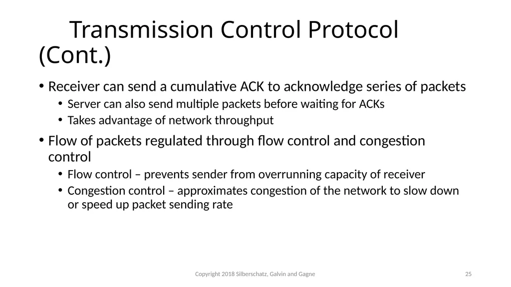
slide25. Transmission Control Protocol (Cont.) Receiver can send a cumulative ACK to acknowledge series of packets
Server can also send multiple packets before waiting for ACKs
Takes advantage of network throughput
Flow of packets regulated through flow control and congestion control
Flow control – prevents sender from overrunning capacity of receiver
Congestion control – approximates congestion of the network to slow down or speed up packet sending rate Copyright 2018 Silberschatz, Galvin and Gagne 25<br>
slide26. Network-oriented Operating Systems Two main types
Network Operating Systems
Users are aware of multiplicity of machines
Distributed Operating Systems
Users not aware of multiplicity of machines Copyright 2018 Silberschatz, Galvin and Gagne 26<br>
slide27. Network Operating Systems Users are aware of multiplicity of machines
Access to resources of various machines is done explicitly by:
Remote logging into the appropriate remote machine (ssh)
ssh kristen.cs.yale.edu
Transferring data from remote machines to local machines, via the File Transfer Protocol (FTP) mechanism
Upload, download, access, or share files through cloud storage
Users must change paradigms – establish a session, give network-based commands, use a web browser
More difficult for users Copyright 2018 Silberschatz, Galvin and Gagne 27<br>
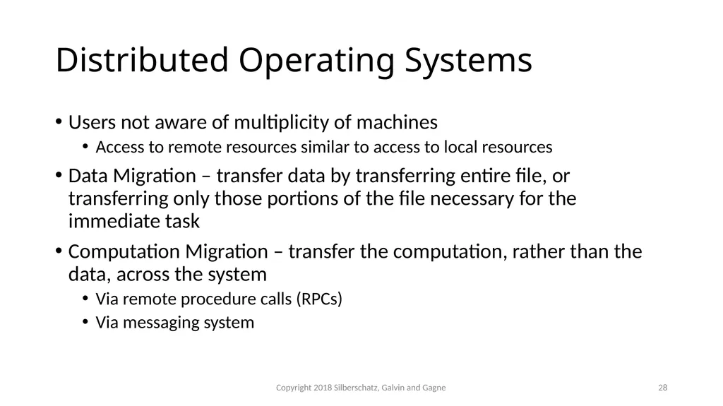
slide28. Distributed Operating Systems Users not aware of multiplicity of machines
Access to remote resources similar to access to local resources
Data Migration – transfer data by transferring entire file, or transferring only those portions of the file necessary for the immediate task
Computation Migration – transfer the computation, rather than the data, across the system
Via remote procedure calls (RPCs)
Via messaging system Copyright 2018 Silberschatz, Galvin and Gagne 28<br>
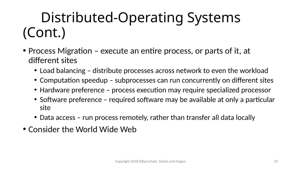
slide29. Distributed-Operating Systems (Cont.) Process Migration – execute an entire process, or parts of it, at different sites
Load balancing – distribute processes across network to even the workload
Computation speedup – subprocesses can run concurrently on different sites
Hardware preference – process execution may require specialized processor
Software preference – required software may be available at only a particular site
Data access – run process remotely, rather than transfer all data locally
Consider the World Wide Web Copyright 2018 Silberschatz, Galvin and Gagne 29<br>
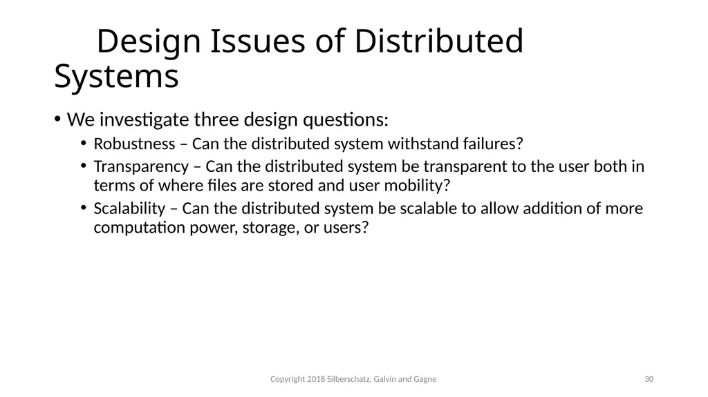
slide30. Design Issues of Distributed Systems We investigate three design questions:
Robustness – Can the distributed system withstand failures?
Transparency – Can the distributed system be transparent to the user both in terms of where files are stored and user mobility?
Scalability – Can the distributed system be scalable to allow addition of more computation power, storage, or users? Copyright 2018 Silberschatz, Galvin and Gagne 30<br>
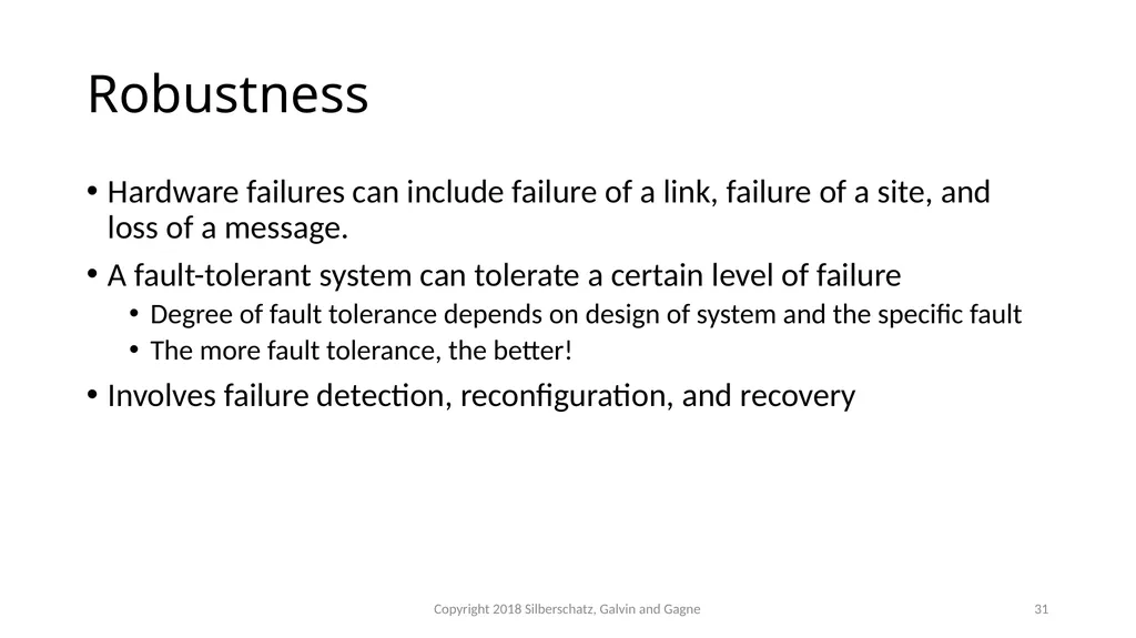
slide31. Robustness Hardware failures can include failure of a link, failure of a site, and loss of a message.
A fault-tolerant system can tolerate a certain level of failure
Degree of fault tolerance depends on design of system and the specific fault
The more fault tolerance, the better!
Involves failure detection, reconfiguration, and recovery Copyright 2018 Silberschatz, Galvin and Gagne 31<br>
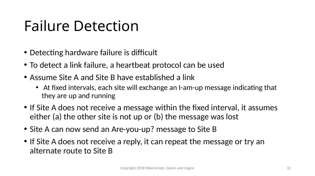
slide32. Failure Detection Detecting hardware failure is difficult
To detect a link failure, a heartbeat protocol can be used
Assume Site A and Site B have established a link
At fixed intervals, each site will exchange an I-am-up message indicating that they are up and running
If Site A does not receive a message within the fixed interval, it assumes either (a) the other site is not up or (b) the message was lost
Site A can now send an Are-you-up? message to Site B
If Site A does not receive a reply, it can repeat the message or try an alternate route to Site B Copyright 2018 Silberschatz, Galvin and Gagne 32<br>
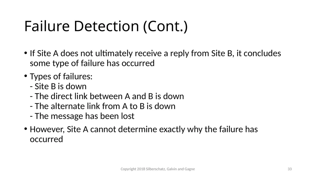
slide33. Failure Detection (Cont.) If Site A does not ultimately receive a reply from Site B, it concludes some type of failure has occurred
Types of failures: - Site B is down - The direct link between A and B is down - The alternate link from A to B is down - The message has been lost
However, Site A cannot determine exactly why the failure has occurred Copyright 2018 Silberschatz, Galvin and Gagne 33<br>
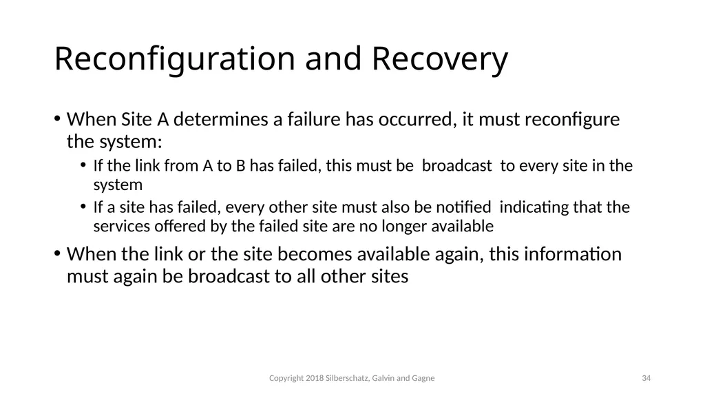
slide34. Reconfiguration and Recovery When Site A determines a failure has occurred, it must reconfigure the system:
If the link from A to B has failed, this must be broadcast to every site in the system
If a site has failed, every other site must also be notified indicating that the services offered by the failed site are no longer available
When the link or the site becomes available again, this information must again be broadcast to all other sites Copyright 2018 Silberschatz, Galvin and Gagne 34<br>
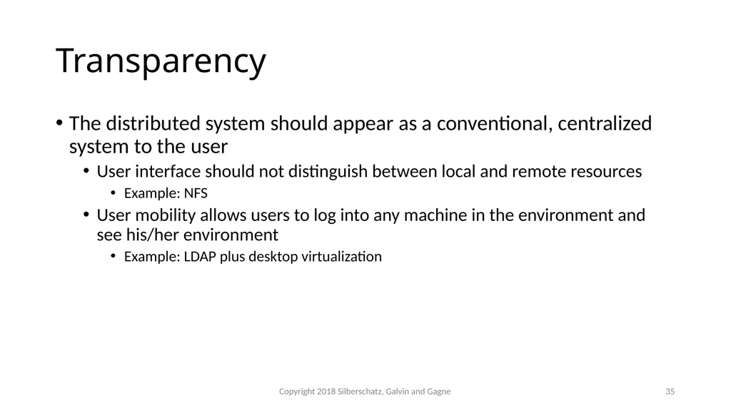
slide35. Transparency The distributed system should appear as a conventional, centralized system to the user
User interface should not distinguish between local and remote resources
Example: NFS
User mobility allows users to log into any machine in the environment and see his/her environment
Example: LDAP plus desktop virtualization Copyright 2018 Silberschatz, Galvin and Gagne 35<br>
slide36. Scalability As demands increase, the system should easily accept the addition of new resources to accommodate the increased demand
Reacts gracefully to increased load
Adding more resources may generate additional indirect load on other resources if not careful
Data compression or deduplication can cut down on storage and network resources used Copyright 2018 Silberschatz, Galvin and Gagne 36<br>
slide37. Distributed File System Distributed file system (DFS) – a file system whose clients, servers, and storage devices are dispersed among the machines of a distributed system
Should appear to its clients as a conventional, centralized file system
Key distinguishing feature is management of dispersed storage devices Copyright 2018 Silberschatz, Galvin and Gagne 37<br>
slide38. Distributed File System (Cont.) Service – software entity running on one or more machines and providing a particular type of function to a priori unknown clients
Server – service software running on a single machine
Client – process that can invoke a service using a set of operations that forms its client interface
A client interface for a file service is formed by a set of primitive file operations (create, delete, read, write)
Client interface of a DFS should be transparent; i.e., not distinguish between local and remote files
Sometimes lower level inter-machine interface need for cross-machine interaction Copyright 2018 Silberschatz, Galvin and Gagne 38<br>
slide39. Distributed File System (Cont.) Two widely-used architectural models include client-server model and cluster-based model
Challenges include:
Naming and transparency
Remote file access
Caching and cache consistency Copyright 2018 Silberschatz, Galvin and Gagne 39<br>
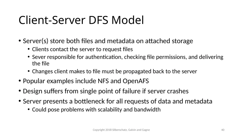
slide40. Client-Server DFS Model Server(s) store both files and metadata on attached storage
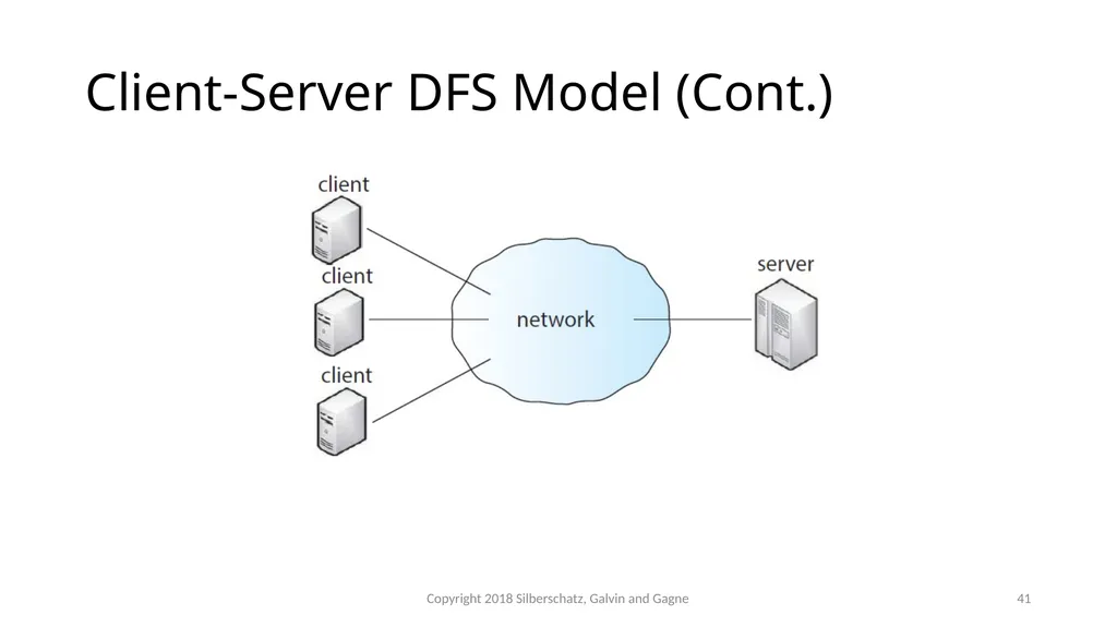
Clients contact the server to request files
Sever responsible for authentication, checking file permissions, and delivering the file
Changes client makes to file must be propagated back to the server
Popular examples include NFS and OpenAFS
Design suffers from single point of failure if server crashes
Server presents a bottleneck for all requests of data and metadata
Could pose problems with scalability and bandwidth Copyright 2018 Silberschatz, Galvin and Gagne 40<br>
slide41. Client-Server DFS Model (Cont.) Copyright 2018 Silberschatz, Galvin and Gagne 41<br>
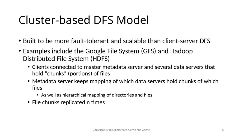
slide42. Cluster-based DFS Model Built to be more fault-tolerant and scalable than client-server DFS
Examples include the Google File System (GFS) and Hadoop Distributed File System (HDFS)
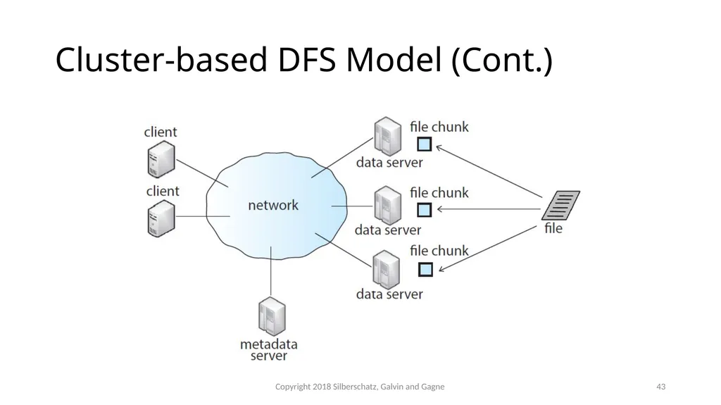
Clients connected to master metadata server and several data servers that hold “chunks” (portions) of files
Metadata server keeps mapping of which data servers hold chunks of which files
As well as hierarchical mapping of directories and files
File chunks replicated n times Copyright 2018 Silberschatz, Galvin and Gagne 42<br>
slide43. Cluster-based DFS Model (Cont.) Copyright 2018 Silberschatz, Galvin and Gagne 43<br>
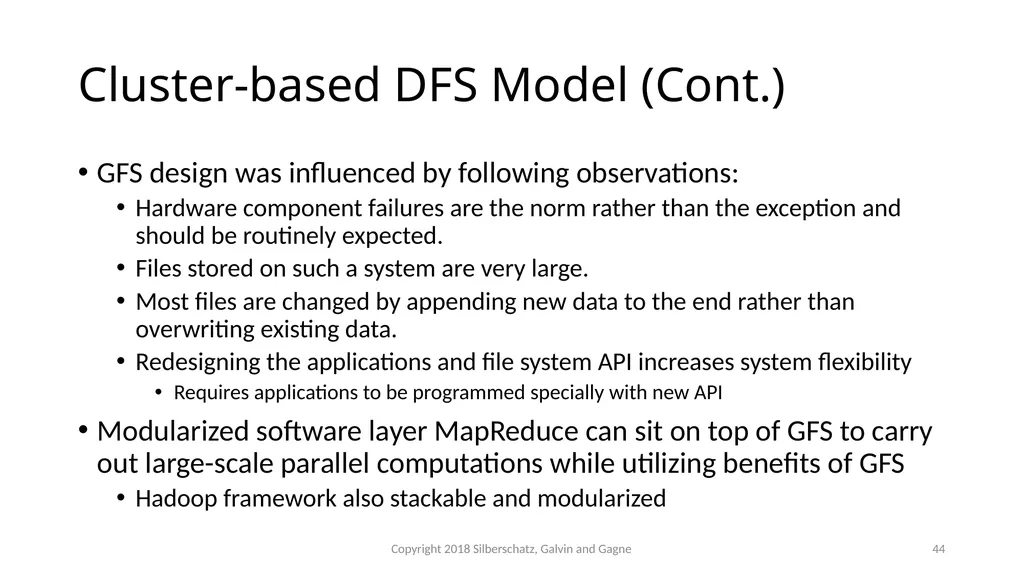
slide44. Cluster-based DFS Model (Cont.) GFS design was influenced by following observations:
Hardware component failures are the norm rather than the exception and should be routinely expected.
Files stored on such a system are very large.
Most files are changed by appending new data to the end rather than overwriting existing data.
Redesigning the applications and file system API increases system flexibility
Requires applications to be programmed specially with new API
Modularized software layer MapReduce can sit on top of GFS to carry out large-scale parallel computations while utilizing benefits of GFS
Hadoop framework also stackable and modularized Copyright 2018 Silberschatz, Galvin and Gagne 44<br>
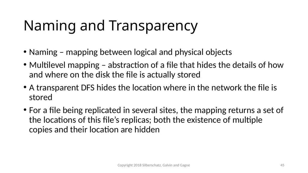
slide45. Naming and Transparency Naming – mapping between logical and physical objects
Multilevel mapping – abstraction of a file that hides the details of how and where on the disk the file is actually stored
A transparent DFS hides the location where in the network the file is stored
For a file being replicated in several sites, the mapping returns a set of the locations of this file’s replicas; both the existence of multiple copies and their location are hidden Copyright 2018 Silberschatz, Galvin and Gagne 45<br>
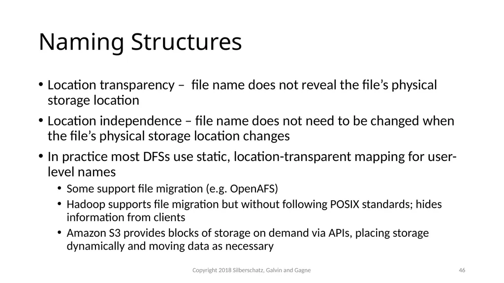
slide46. Naming Structures Location transparency – file name does not reveal the file’s physical storage location
Location independence – file name does not need to be changed when the file’s physical storage location changes
In practice most DFSs use static, location-transparent mapping for user-level names
Some support file migration (e.g. OpenAFS)
Hadoop supports file migration but without following POSIX standards; hides information from clients
Amazon S3 provides blocks of storage on demand via APIs, placing storage dynamically and moving data as necessary Copyright 2018 Silberschatz, Galvin and Gagne 46<br>
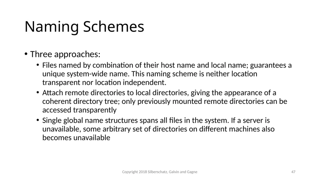
slide47. Naming Schemes Three approaches:
Files named by combination of their host name and local name; guarantees a unique system-wide name. This naming scheme is neither location transparent nor location independent.
Attach remote directories to local directories, giving the appearance of a coherent directory tree; only previously mounted remote directories can be accessed transparently
Single global name structures spans all files in the system. If a server is unavailable, some arbitrary set of directories on different machines also becomes unavailable Copyright 2018 Silberschatz, Galvin and Gagne 47<br>
slide48. Remote File Access Consider a user who requests access to a remote file. The server storing the file has been located by the naming scheme, and now the actual data transfer must take place.
Remote-service mechanism is one transfer approach.
A request for accesses are delivered to the server, the server machine performs the accesses, and their results are forwarded back to the user.
One of the most common ways of implementing remote service is the RPC paradigm Copyright 2018 Silberschatz, Galvin and Gagne 48<br>
slide49. Remote File Access (Cont.) Reduce network traffic by retaining recently accessed disk blocks in a cache, so that repeated accesses to the same information can be handled locally
If needed data is not already cached, a copy of data is brought from the server to the user
Accesses are performed on the cached copy
Files identified with one master copy residing at the server machine, but copies of (parts of) the file are scattered in different caches
Cache-consistency problem – keeping the cached copies consistent with the master file
Could be called network virtual memory Copyright 2018 Silberschatz, Galvin and Gagne 49<br>
slide50. Cache Location – Disk vs. Main Memory Advantages of disk caches
More reliable
Cached data kept on disk are still there during recovery and don’t need to be fetched again
Advantages of main-memory caches:
Permit workstations to be diskless
Data can be accessed more quickly
Performance speedup in bigger memories
Server caches (used to speed up disk I/O) are in main memory regardless of where user caches are located; using main-memory caches on the user machine permits a single caching mechanism for servers and users Copyright 2018 Silberschatz, Galvin and Gagne 50<br>
slide51. Cache Update Policy Write-through – write data through to disk as soon as they are placed on any cache
Reliable, but poor performance
Delayed-write (write-back) – modifications are written to the cache and then written through to the server later
Write accesses complete quickly; some data may be overwritten before they are written back, and so need never be written at all
Poor reliability; unwritten data will be lost whenever a user machine crashes
Variation – scan cache at regular intervals and flush blocks that have been modified since the last scan
Variation – write-on-close, writes data back to the server when the file is closed
Best for files that are open for long periods and frequently modified Copyright 2018 Silberschatz, Galvin and Gagne 51<br>
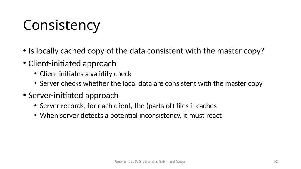
slide52. Consistency Is locally cached copy of the data consistent with the master copy?
Client-initiated approach
Client initiates a validity check
Server checks whether the local data are consistent with the master copy
Server-initiated approach
Server records, for each client, the (parts of) files it caches
When server detects a potential inconsistency, it must react Copyright 2018 Silberschatz, Galvin and Gagne 52<br>
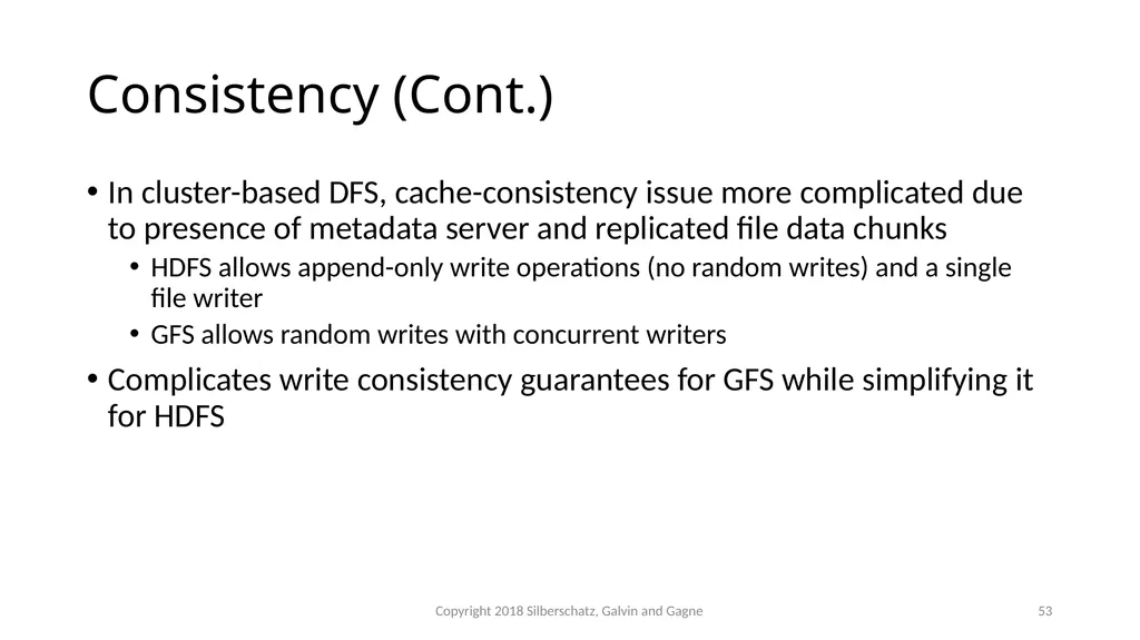
slide53. Consistency (Cont.) In cluster-based DFS, cache-consistency issue more complicated due to presence of metadata server and replicated file data chunks
HDFS allows append-only write operations (no random writes) and a single file writer
GFS allows random writes with concurrent writers
Complicates write consistency guarantees for GFS while simplifying it for HDFS Copyright 2018 Silberschatz, Galvin and Gagne 53<br>
slide54. The Sun Network File System (NFS) An implementation and a specification of a software system for accessing remote files across LANs (or WANs)
The implementation is part of the Solaris and SunOS operating systems running on Sun workstations using an unreliable datagram protocol (UDP/IP protocol) and Ethernet
Later version support TCP also Copyright 2018 Silberschatz, Galvin and Gagne 54<br>
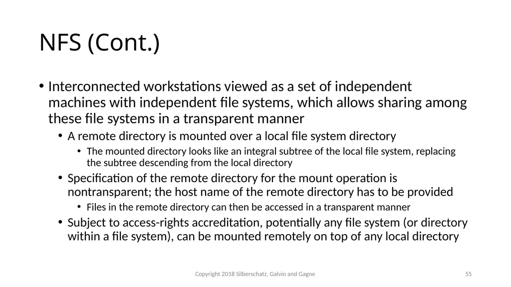
slide55. NFS (Cont.) Interconnected workstations viewed as a set of independent machines with independent file systems, which allows sharing among these file systems in a transparent manner
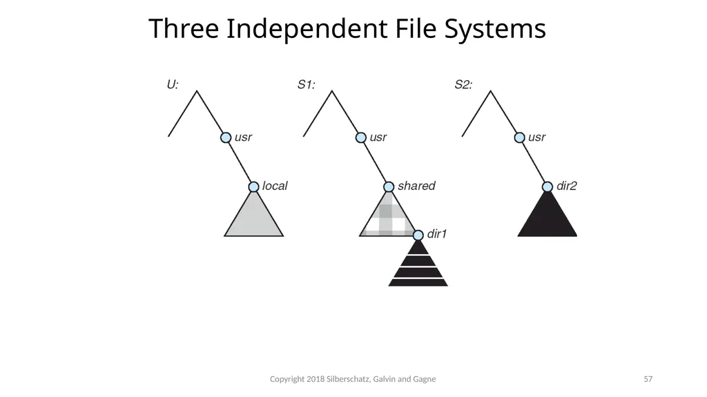
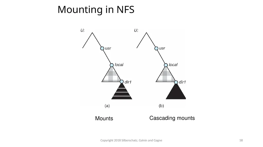
A remote directory is mounted over a local file system directory
The mounted directory looks like an integral subtree of the local file system, replacing the subtree descending from the local directory
Specification of the remote directory for the mount operation is nontransparent; the host name of the remote directory has to be provided
Files in the remote directory can then be accessed in a transparent manner
Subject to access-rights accreditation, potentially any file system (or directory within a file system), can be mounted remotely on top of any local directory Copyright 2018 Silberschatz, Galvin and Gagne 55<br>
slide56. NFS (Cont.) NFS is designed to operate in a heterogeneous environment of different machines, operating systems, and network architectures; the NFS specifications independent of these media
This independence is achieved through the use of RPC primitives built on top of an External Data Representation (XDR) protocol used between two implementation-independent interfaces
The NFS specification distinguishes between the services provided by a mount mechanism and the actual remote-file-access services Copyright 2018 Silberschatz, Galvin and Gagne 56<br>
slide57. Three Independent File Systems Copyright 2018 Silberschatz, Galvin and Gagne 57<br>
slide58. Mounting in NFS Mounts Cascading mounts Copyright 2018 Silberschatz, Galvin and Gagne 58<br>
slide59. NFS Mount Protocol Establishes initial logical connection between server and client
Mount operation includes name of remote directory to be mounted and name of server machine storing it
Mount request is mapped to corresponding RPC and forwarded to mount server running on server machine
Export list – specifies local file systems that server exports for mounting, along with names of machines that are permitted to mount them
Following a mount request that conforms to its export list, the server returns a file handle—a key for further accesses
File handle – a file-system identifier, and an inode number to identify the mounted directory within the exported file system
The mount operation changes only the user’s view and does not affect the server side Copyright 2018 Silberschatz, Galvin and Gagne 59<br>
slide60. NFS Protocol Provides a set of remote procedure calls for remote file operations. The procedures support the following operations:
searching for a file within a directory
reading a set of directory entries
manipulating links and directories
accessing file attributes
reading and writing files
NFS servers are stateless; each request has to provide a full set of arguments (NFS V4 is just coming available – very different, stateful)
Modified data must be committed to the server’s disk before results are returned to the client (lose advantages of caching)
The NFS protocol does not provide concurrency-control mechanisms Copyright 2018 Silberschatz, Galvin and Gagne 60<br>
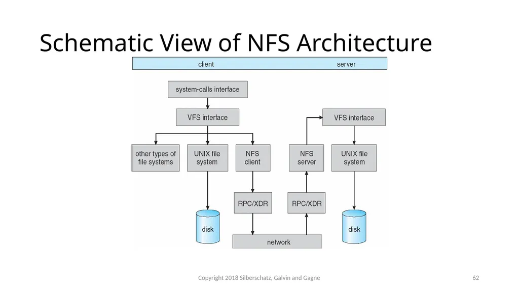
slide61. Three Major Layers of NFS Architecture UNIX file-system interface (based on the open, read, write, and close calls, and file descriptors)
Virtual File System (VFS) layer – distinguishes local files from remote ones, and local files are further distinguished according to their file-system types
The VFS activates file-system-specific operations to handle local requests according to their file-system types
Calls the NFS protocol procedures for remote requests
NFS service layer – bottom layer of the architecture
Implements the NFS protocol Copyright 2018 Silberschatz, Galvin and Gagne 61<br>
slide62. Schematic View of NFS Architecture Copyright 2018 Silberschatz, Galvin and Gagne 62<br>
slide63. NFS Path-Name Translation Performed by breaking the path into component names and performing a separate NFS lookup call for every pair of component name and directory vnode
To make lookup faster, a directory name lookup cache on the client’s side holds the vnodes for remote directory names Copyright 2018 Silberschatz, Galvin and Gagne 63<br>
slide64. NFS Remote Operations Nearly one-to-one correspondence between regular UNIX system calls and the NFS protocol RPCs (except opening and closing files)
NFS adheres to the remote-service paradigm, but employs buffering and caching techniques for the sake of performance
File-blocks cache – when a file is opened, the kernel checks with the remote server whether to fetch or revalidate the cached attributes
Cached file blocks are used only if the corresponding cached attributes are up to date
File-attribute cache – the attribute cache is updated whenever new attributes arrive from the server
Clients do not free delayed-write blocks until the server confirms that the data have been written to disk Copyright 2018 Silberschatz, Galvin and Gagne 64<br>
Prof. Ashok K Agrawala
Online Set 13
Distributed Systems 1<br>
slide2. Overview A distributed system is a collection of loosely coupled nodes interconnected by a communications network
Nodes variously called processors, computers, machines, hosts
Site is location of the machine,
Node refers to specific system
Generally a server has a resource a client node at a different site wants to use Copyright 2018 Silberschatz, Galvin and Gagne 2<br>
slide3. Overview (cont.) Nodes may exist in a client-server, peer-to-peer, or hybrid configuration.
In client-server configuration, server has a resource that a client would like to use
In peer-to-peer configuration, each node shares equal responsibilities and can act as both clients and servers
Communication over a network occurs through message passing
All higher-level functions of a standalone system can be expanded to encompass a distributed system Copyright 2018 Silberschatz, Galvin and Gagne 3<br>
slide4. Reasons for Distributed Systems Resource sharing
Sharing files or printing at remote sites
Processing information in a distributed database
Using remote specialized hardware devices such as graphics processing units (GPUs)
Computation speedup
Distribute subcomputations among various sites to run concurrently
Load balancing – moving jobs to more lightly-loaded sites
Reliability
Detect and recover from site failure, function transfer, reintegrate failed site Copyright 2018 Silberschatz, Galvin and Gagne 4<br>
slide5. Network Structure Local-Area Network (LAN) – designed to cover small geographical area
Consists of multiple computers (workstations, laptops, mobile devices), peripherals (printers, storage arrays), and routers providing access to other networks
Ethernet and/or Wireless (WiFi) most common way to construct LANs
Ethernet defined by standard IEEE 802.3 with speeds typically varying from 10Mbps to over 10Gbps
WiFi defined by standard IEEE 802.11 with speeds typically varying from 11Mbps to over 400Mbps.
Both standards constantly evolving Copyright 2018 Silberschatz, Galvin and Gagne 5<br>
slide6. Local-Area Network (LAN) Copyright 2018 Silberschatz, Galvin and Gagne 6<br>
slide7. Network Structure (Cont.) Wide-Area Network (WAN) – links geographically separated sites
Point-to-point connections via links
Telephone lines, leased (dedicated data) lines, optical cable, microwave links, radio waves, and satellite channels
Implemented via routers to direct traffic from one network to another
Internet (World Wide Web) WAN enables hosts world wide to communicate
Speeds vary
Many backbone providers have speeds at 40-100Gbps
Local Internet Service Providers (ISPs) may be slower
WAN links constantly being upgraded
WANs and LANs interconnect, similar to cell phone network:
Cell phones use radio waves to cell towers
Towers connect to other towers and hubs Copyright 2018 Silberschatz, Galvin and Gagne 7<br>
slide8. Wide-Area Network (WAN) Copyright 2018 Silberschatz, Galvin and Gagne 8<br>
slide9. Naming and Name Resolution Each computer system in the network has a unique name
Each process in a given system has a unique name (process-id)
Identify processes on remote systems by
<host-name, identifier> pair
Domain name system (DNS) – specifies the naming structure of the hosts, as well as name to address resolution (Internet) Copyright 2018 Silberschatz, Galvin and Gagne 9<br>
slide10. Communication Protocol Layer 1: Physical layer – handles the mechanical and electrical details of the physical transmission of a bit stream
Layer 2: Data-link layer – handles the frames, or fixed-length parts of packets, including any error detection and recovery that occurred in the physical layer
Layer 3: Network layer – provides connections and routes packets in the communication network, including handling the address of outgoing packets, decoding the address of incoming packets, and maintaining routing information for proper response to changing load levels The communication network is partitioned into the following multiple layers: Copyright 2018 Silberschatz, Galvin and Gagne 10<br>
slide11. Communication Protocol (Cont.) Layer 4: Transport layer – responsible for low-level network access and for message transfer between clients, including partitioning messages into packets, maintaining packet order, controlling flow, and generating physical addresses
Layer 5: Session layer – implements sessions, or process-to-process communications protocols
Layer 6: Presentation layer – resolves the differences in formats among the various sites in the network, including character conversions, and half duplex/full duplex (echoing)
Layer 7: Application layer – interacts directly with the users, deals with file transfer, remote-login protocols and electronic mail, as well as schemas for distributed databases Copyright 2018 Silberschatz, Galvin and Gagne 11<br>
slide12. Logical communication between two computers, with the three lowest-level layers implemented in hardware OSI Network Model Copyright 2018 Silberschatz, Galvin and Gagne 12<br>
slide13. OSI Protocol Stack Copyright 2018 Silberschatz, Galvin and Gagne 13<br>
slide14. OSI Network Message Copyright 2018 Silberschatz, Galvin and Gagne 14<br>
slide15. The OSI model The OSI model formalizes some of the earlier work done in network protocols but was developed in the late 1970s and is currently not in widespread use
The most widely adopted protocol stack is the TCP/IP model, which has been adopted by virtually all Internet sites
The TCP/IP protocol stack has fewer layers than the OSI model. Theoretically, because it combines several functions in each layer, it is more difficult to implement but more efficient than OSI networking
The relationship between the OSI and TCP/IP models is shown in the next slide Copyright 2018 Silberschatz, Galvin and Gagne 15<br>
slide16. The OSI and TCP/IP Protocol Stacks Copyright 2018 Silberschatz, Galvin and Gagne 16<br>
slide17. TCP/IP Example Every host has a name and an associated IP address (host-id)
Hierarchical and segmented
Sending system checks routing tables and locates a router to send packet
Router uses segmented network part of host-id to determine where to transfer packet
This may repeat among multiple routers
Destination system receives the packet
Packet may be complete message, or it may need to be reassembled into larger message spanning multiple packets Copyright 2018 Silberschatz, Galvin and Gagne 17<br>
slide18. TCP/IP Example (Cont.) Within a network, how does a packet move from sender (host or router) to receiver?
Every Ethernet/WiFi device has a medium access control (MAC) address
Two devices on same LAN communicate via MAC address
If a system needs to send data to another system, it needs to discover the IP to MAC address mapping
Uses address resolution protocol (ARP)
A broadcast uses a special network address to signal that all hosts should receive and process the packet
Not forwarded by routers to different networks Copyright 2018 Silberschatz, Galvin and Gagne 18<br>
slide19. Ethernet Packet Copyright 2018 Silberschatz, Galvin and Gagne 19<br>
slide20. Transport Protocols UDP and TCP Once a host with a specific IP address receives a packet, it must somehow pass it to the correct waiting process
Transport protocols TCP and UDP identify receiving and sending processes through the use of a port number
Allows host with single IP address to have multiple server/client processes sending/receiving packets
Well-known port numbers are used for many services
FTP – port 21
ssh – port 22
SMTP – port 25
HTTP – port 80
Transport protocol can be simple or can add reliability to network packet stream Copyright 2018 Silberschatz, Galvin and Gagne 20<br>
slide21. User Datagram Protocol UDP is unreliable – bare-bones extension to IP with addition of port number
Since there are no guarantees of delivery in the lower network (IP) layer, packets may become lost
Packets may also be received out-out-order
UDP is also connectionless – no connection setup at the beginning of the transmission to set up state
Also no connection tear-down at the end of transmission
UDP packets are also called datagrams Copyright 2018 Silberschatz, Galvin and Gagne 21<br>
slide22. UDP Dropped Packet Example Copyright 2018 Silberschatz, Galvin and Gagne 22<br>
slide23. Transmission Control Protocol TCP is both reliable and connection-oriented
In addition to port number, TCP provides abstraction to allow in-order, uninterrupted byte-stream across an unreliable network
Whenever host sends packet, the receiver must send an acknowledgement packet (ACK). If ACK not received before a timer expires, sender will resend.
Sequence numbers in TCP header allow receiver to put packets in order and notice missing packets
Connections are initiated with series of control packets called a three-way handshake
Connections also closed with series of control packets Copyright 2018 Silberschatz, Galvin and Gagne 23<br>
slide24. TCP Data Transfer Scenario Copyright 2018 Silberschatz, Galvin and Gagne 24<br>
slide25. Transmission Control Protocol (Cont.) Receiver can send a cumulative ACK to acknowledge series of packets
Server can also send multiple packets before waiting for ACKs
Takes advantage of network throughput
Flow of packets regulated through flow control and congestion control
Flow control – prevents sender from overrunning capacity of receiver
Congestion control – approximates congestion of the network to slow down or speed up packet sending rate Copyright 2018 Silberschatz, Galvin and Gagne 25<br>
slide26. Network-oriented Operating Systems Two main types
Network Operating Systems
Users are aware of multiplicity of machines
Distributed Operating Systems
Users not aware of multiplicity of machines Copyright 2018 Silberschatz, Galvin and Gagne 26<br>
slide27. Network Operating Systems Users are aware of multiplicity of machines
Access to resources of various machines is done explicitly by:
Remote logging into the appropriate remote machine (ssh)
ssh kristen.cs.yale.edu
Transferring data from remote machines to local machines, via the File Transfer Protocol (FTP) mechanism
Upload, download, access, or share files through cloud storage
Users must change paradigms – establish a session, give network-based commands, use a web browser
More difficult for users Copyright 2018 Silberschatz, Galvin and Gagne 27<br>
slide28. Distributed Operating Systems Users not aware of multiplicity of machines
Access to remote resources similar to access to local resources
Data Migration – transfer data by transferring entire file, or transferring only those portions of the file necessary for the immediate task
Computation Migration – transfer the computation, rather than the data, across the system
Via remote procedure calls (RPCs)
Via messaging system Copyright 2018 Silberschatz, Galvin and Gagne 28<br>
slide29. Distributed-Operating Systems (Cont.) Process Migration – execute an entire process, or parts of it, at different sites
Load balancing – distribute processes across network to even the workload
Computation speedup – subprocesses can run concurrently on different sites
Hardware preference – process execution may require specialized processor
Software preference – required software may be available at only a particular site
Data access – run process remotely, rather than transfer all data locally
Consider the World Wide Web Copyright 2018 Silberschatz, Galvin and Gagne 29<br>
slide30. Design Issues of Distributed Systems We investigate three design questions:
Robustness – Can the distributed system withstand failures?
Transparency – Can the distributed system be transparent to the user both in terms of where files are stored and user mobility?
Scalability – Can the distributed system be scalable to allow addition of more computation power, storage, or users? Copyright 2018 Silberschatz, Galvin and Gagne 30<br>
slide31. Robustness Hardware failures can include failure of a link, failure of a site, and loss of a message.
A fault-tolerant system can tolerate a certain level of failure
Degree of fault tolerance depends on design of system and the specific fault
The more fault tolerance, the better!
Involves failure detection, reconfiguration, and recovery Copyright 2018 Silberschatz, Galvin and Gagne 31<br>
slide32. Failure Detection Detecting hardware failure is difficult
To detect a link failure, a heartbeat protocol can be used
Assume Site A and Site B have established a link
At fixed intervals, each site will exchange an I-am-up message indicating that they are up and running
If Site A does not receive a message within the fixed interval, it assumes either (a) the other site is not up or (b) the message was lost
Site A can now send an Are-you-up? message to Site B
If Site A does not receive a reply, it can repeat the message or try an alternate route to Site B Copyright 2018 Silberschatz, Galvin and Gagne 32<br>
slide33. Failure Detection (Cont.) If Site A does not ultimately receive a reply from Site B, it concludes some type of failure has occurred
Types of failures: - Site B is down - The direct link between A and B is down - The alternate link from A to B is down - The message has been lost
However, Site A cannot determine exactly why the failure has occurred Copyright 2018 Silberschatz, Galvin and Gagne 33<br>
slide34. Reconfiguration and Recovery When Site A determines a failure has occurred, it must reconfigure the system:
If the link from A to B has failed, this must be broadcast to every site in the system
If a site has failed, every other site must also be notified indicating that the services offered by the failed site are no longer available
When the link or the site becomes available again, this information must again be broadcast to all other sites Copyright 2018 Silberschatz, Galvin and Gagne 34<br>
slide35. Transparency The distributed system should appear as a conventional, centralized system to the user
User interface should not distinguish between local and remote resources
Example: NFS
User mobility allows users to log into any machine in the environment and see his/her environment
Example: LDAP plus desktop virtualization Copyright 2018 Silberschatz, Galvin and Gagne 35<br>
slide36. Scalability As demands increase, the system should easily accept the addition of new resources to accommodate the increased demand
Reacts gracefully to increased load
Adding more resources may generate additional indirect load on other resources if not careful
Data compression or deduplication can cut down on storage and network resources used Copyright 2018 Silberschatz, Galvin and Gagne 36<br>
slide37. Distributed File System Distributed file system (DFS) – a file system whose clients, servers, and storage devices are dispersed among the machines of a distributed system
Should appear to its clients as a conventional, centralized file system
Key distinguishing feature is management of dispersed storage devices Copyright 2018 Silberschatz, Galvin and Gagne 37<br>
slide38. Distributed File System (Cont.) Service – software entity running on one or more machines and providing a particular type of function to a priori unknown clients
Server – service software running on a single machine
Client – process that can invoke a service using a set of operations that forms its client interface
A client interface for a file service is formed by a set of primitive file operations (create, delete, read, write)
Client interface of a DFS should be transparent; i.e., not distinguish between local and remote files
Sometimes lower level inter-machine interface need for cross-machine interaction Copyright 2018 Silberschatz, Galvin and Gagne 38<br>
slide39. Distributed File System (Cont.) Two widely-used architectural models include client-server model and cluster-based model
Challenges include:
Naming and transparency
Remote file access
Caching and cache consistency Copyright 2018 Silberschatz, Galvin and Gagne 39<br>
slide40. Client-Server DFS Model Server(s) store both files and metadata on attached storage
Clients contact the server to request files
Sever responsible for authentication, checking file permissions, and delivering the file
Changes client makes to file must be propagated back to the server
Popular examples include NFS and OpenAFS
Design suffers from single point of failure if server crashes
Server presents a bottleneck for all requests of data and metadata
Could pose problems with scalability and bandwidth Copyright 2018 Silberschatz, Galvin and Gagne 40<br>
slide41. Client-Server DFS Model (Cont.) Copyright 2018 Silberschatz, Galvin and Gagne 41<br>
slide42. Cluster-based DFS Model Built to be more fault-tolerant and scalable than client-server DFS
Examples include the Google File System (GFS) and Hadoop Distributed File System (HDFS)
Clients connected to master metadata server and several data servers that hold “chunks” (portions) of files
Metadata server keeps mapping of which data servers hold chunks of which files
As well as hierarchical mapping of directories and files
File chunks replicated n times Copyright 2018 Silberschatz, Galvin and Gagne 42<br>
slide43. Cluster-based DFS Model (Cont.) Copyright 2018 Silberschatz, Galvin and Gagne 43<br>
slide44. Cluster-based DFS Model (Cont.) GFS design was influenced by following observations:
Hardware component failures are the norm rather than the exception and should be routinely expected.
Files stored on such a system are very large.
Most files are changed by appending new data to the end rather than overwriting existing data.
Redesigning the applications and file system API increases system flexibility
Requires applications to be programmed specially with new API
Modularized software layer MapReduce can sit on top of GFS to carry out large-scale parallel computations while utilizing benefits of GFS
Hadoop framework also stackable and modularized Copyright 2018 Silberschatz, Galvin and Gagne 44<br>
slide45. Naming and Transparency Naming – mapping between logical and physical objects
Multilevel mapping – abstraction of a file that hides the details of how and where on the disk the file is actually stored
A transparent DFS hides the location where in the network the file is stored
For a file being replicated in several sites, the mapping returns a set of the locations of this file’s replicas; both the existence of multiple copies and their location are hidden Copyright 2018 Silberschatz, Galvin and Gagne 45<br>
slide46. Naming Structures Location transparency – file name does not reveal the file’s physical storage location
Location independence – file name does not need to be changed when the file’s physical storage location changes
In practice most DFSs use static, location-transparent mapping for user-level names
Some support file migration (e.g. OpenAFS)
Hadoop supports file migration but without following POSIX standards; hides information from clients
Amazon S3 provides blocks of storage on demand via APIs, placing storage dynamically and moving data as necessary Copyright 2018 Silberschatz, Galvin and Gagne 46<br>
slide47. Naming Schemes Three approaches:
Files named by combination of their host name and local name; guarantees a unique system-wide name. This naming scheme is neither location transparent nor location independent.
Attach remote directories to local directories, giving the appearance of a coherent directory tree; only previously mounted remote directories can be accessed transparently
Single global name structures spans all files in the system. If a server is unavailable, some arbitrary set of directories on different machines also becomes unavailable Copyright 2018 Silberschatz, Galvin and Gagne 47<br>
slide48. Remote File Access Consider a user who requests access to a remote file. The server storing the file has been located by the naming scheme, and now the actual data transfer must take place.
Remote-service mechanism is one transfer approach.
A request for accesses are delivered to the server, the server machine performs the accesses, and their results are forwarded back to the user.
One of the most common ways of implementing remote service is the RPC paradigm Copyright 2018 Silberschatz, Galvin and Gagne 48<br>
slide49. Remote File Access (Cont.) Reduce network traffic by retaining recently accessed disk blocks in a cache, so that repeated accesses to the same information can be handled locally
If needed data is not already cached, a copy of data is brought from the server to the user
Accesses are performed on the cached copy
Files identified with one master copy residing at the server machine, but copies of (parts of) the file are scattered in different caches
Cache-consistency problem – keeping the cached copies consistent with the master file
Could be called network virtual memory Copyright 2018 Silberschatz, Galvin and Gagne 49<br>
slide50. Cache Location – Disk vs. Main Memory Advantages of disk caches
More reliable
Cached data kept on disk are still there during recovery and don’t need to be fetched again
Advantages of main-memory caches:
Permit workstations to be diskless
Data can be accessed more quickly
Performance speedup in bigger memories
Server caches (used to speed up disk I/O) are in main memory regardless of where user caches are located; using main-memory caches on the user machine permits a single caching mechanism for servers and users Copyright 2018 Silberschatz, Galvin and Gagne 50<br>
slide51. Cache Update Policy Write-through – write data through to disk as soon as they are placed on any cache
Reliable, but poor performance
Delayed-write (write-back) – modifications are written to the cache and then written through to the server later
Write accesses complete quickly; some data may be overwritten before they are written back, and so need never be written at all
Poor reliability; unwritten data will be lost whenever a user machine crashes
Variation – scan cache at regular intervals and flush blocks that have been modified since the last scan
Variation – write-on-close, writes data back to the server when the file is closed
Best for files that are open for long periods and frequently modified Copyright 2018 Silberschatz, Galvin and Gagne 51<br>
slide52. Consistency Is locally cached copy of the data consistent with the master copy?
Client-initiated approach
Client initiates a validity check
Server checks whether the local data are consistent with the master copy
Server-initiated approach
Server records, for each client, the (parts of) files it caches
When server detects a potential inconsistency, it must react Copyright 2018 Silberschatz, Galvin and Gagne 52<br>
slide53. Consistency (Cont.) In cluster-based DFS, cache-consistency issue more complicated due to presence of metadata server and replicated file data chunks
HDFS allows append-only write operations (no random writes) and a single file writer
GFS allows random writes with concurrent writers
Complicates write consistency guarantees for GFS while simplifying it for HDFS Copyright 2018 Silberschatz, Galvin and Gagne 53<br>
slide54. The Sun Network File System (NFS) An implementation and a specification of a software system for accessing remote files across LANs (or WANs)
The implementation is part of the Solaris and SunOS operating systems running on Sun workstations using an unreliable datagram protocol (UDP/IP protocol) and Ethernet
Later version support TCP also Copyright 2018 Silberschatz, Galvin and Gagne 54<br>
slide55. NFS (Cont.) Interconnected workstations viewed as a set of independent machines with independent file systems, which allows sharing among these file systems in a transparent manner
A remote directory is mounted over a local file system directory
The mounted directory looks like an integral subtree of the local file system, replacing the subtree descending from the local directory
Specification of the remote directory for the mount operation is nontransparent; the host name of the remote directory has to be provided
Files in the remote directory can then be accessed in a transparent manner
Subject to access-rights accreditation, potentially any file system (or directory within a file system), can be mounted remotely on top of any local directory Copyright 2018 Silberschatz, Galvin and Gagne 55<br>
slide56. NFS (Cont.) NFS is designed to operate in a heterogeneous environment of different machines, operating systems, and network architectures; the NFS specifications independent of these media
This independence is achieved through the use of RPC primitives built on top of an External Data Representation (XDR) protocol used between two implementation-independent interfaces
The NFS specification distinguishes between the services provided by a mount mechanism and the actual remote-file-access services Copyright 2018 Silberschatz, Galvin and Gagne 56<br>
slide57. Three Independent File Systems Copyright 2018 Silberschatz, Galvin and Gagne 57<br>
slide58. Mounting in NFS Mounts Cascading mounts Copyright 2018 Silberschatz, Galvin and Gagne 58<br>
slide59. NFS Mount Protocol Establishes initial logical connection between server and client
Mount operation includes name of remote directory to be mounted and name of server machine storing it
Mount request is mapped to corresponding RPC and forwarded to mount server running on server machine
Export list – specifies local file systems that server exports for mounting, along with names of machines that are permitted to mount them
Following a mount request that conforms to its export list, the server returns a file handle—a key for further accesses
File handle – a file-system identifier, and an inode number to identify the mounted directory within the exported file system
The mount operation changes only the user’s view and does not affect the server side Copyright 2018 Silberschatz, Galvin and Gagne 59<br>
slide60. NFS Protocol Provides a set of remote procedure calls for remote file operations. The procedures support the following operations:
searching for a file within a directory
reading a set of directory entries
manipulating links and directories
accessing file attributes
reading and writing files
NFS servers are stateless; each request has to provide a full set of arguments (NFS V4 is just coming available – very different, stateful)
Modified data must be committed to the server’s disk before results are returned to the client (lose advantages of caching)
The NFS protocol does not provide concurrency-control mechanisms Copyright 2018 Silberschatz, Galvin and Gagne 60<br>
slide61. Three Major Layers of NFS Architecture UNIX file-system interface (based on the open, read, write, and close calls, and file descriptors)
Virtual File System (VFS) layer – distinguishes local files from remote ones, and local files are further distinguished according to their file-system types
The VFS activates file-system-specific operations to handle local requests according to their file-system types
Calls the NFS protocol procedures for remote requests
NFS service layer – bottom layer of the architecture
Implements the NFS protocol Copyright 2018 Silberschatz, Galvin and Gagne 61<br>
slide62. Schematic View of NFS Architecture Copyright 2018 Silberschatz, Galvin and Gagne 62<br>
slide63. NFS Path-Name Translation Performed by breaking the path into component names and performing a separate NFS lookup call for every pair of component name and directory vnode
To make lookup faster, a directory name lookup cache on the client’s side holds the vnodes for remote directory names Copyright 2018 Silberschatz, Galvin and Gagne 63<br>
slide64. NFS Remote Operations Nearly one-to-one correspondence between regular UNIX system calls and the NFS protocol RPCs (except opening and closing files)
NFS adheres to the remote-service paradigm, but employs buffering and caching techniques for the sake of performance
File-blocks cache – when a file is opened, the kernel checks with the remote server whether to fetch or revalidate the cached attributes
Cached file blocks are used only if the corresponding cached attributes are up to date
File-attribute cache – the attribute cache is updated whenever new attributes arrive from the server
Clients do not free delayed-write blocks until the server confirms that the data have been written to disk Copyright 2018 Silberschatz, Galvin and Gagne 64<br>