
DER Technical Forum 1 07 June 2022 14:00 start
TF
Published · 60 slides · 0 views

1 / 1






Description
DER Technical Forum 1 07 June 2022 14:00 start Microsoft Teams meeting Join on your computer or mobile app Click here to join the meeting Or call in (audio only) 44 20 3855 5885,,95573971 United Kingdom, London Phone Conference ID: 955
Related Topics
Share
Embed code
Download this presentation From Below
"DER Technical Forum 1 07 June 2022 14:00 start" is the property of its rightful owner. Permission is granted to download and print the materials on this website for personal, non-commercial use only, and to display it on your personal computer provided you do not modify the materials and that you retain all copyright notices contained in the materials. By downloading content from our website, you accept the terms of this agreement.
Presentation Transcript
01
DER Technical Forum 1 07 June 2022
14:00 start Microsoft Teams meeting
Join on your computer or mobile app
Click here to join the meeting
Or call in (audio only)
+44 20 3855 5885,,95573971# United Kingdom, London
Phone Conference ID: 955 739 71#<br>
14:00 start Microsoft Teams meeting
Join on your computer or mobile app
Click here to join the meeting
Or call in (audio only)
+44 20 3855 5885,,95573971# United Kingdom, London
Phone Conference ID: 955 739 71#<br>
02
Welcome, Housekeeping and Introductions 2<br>
03
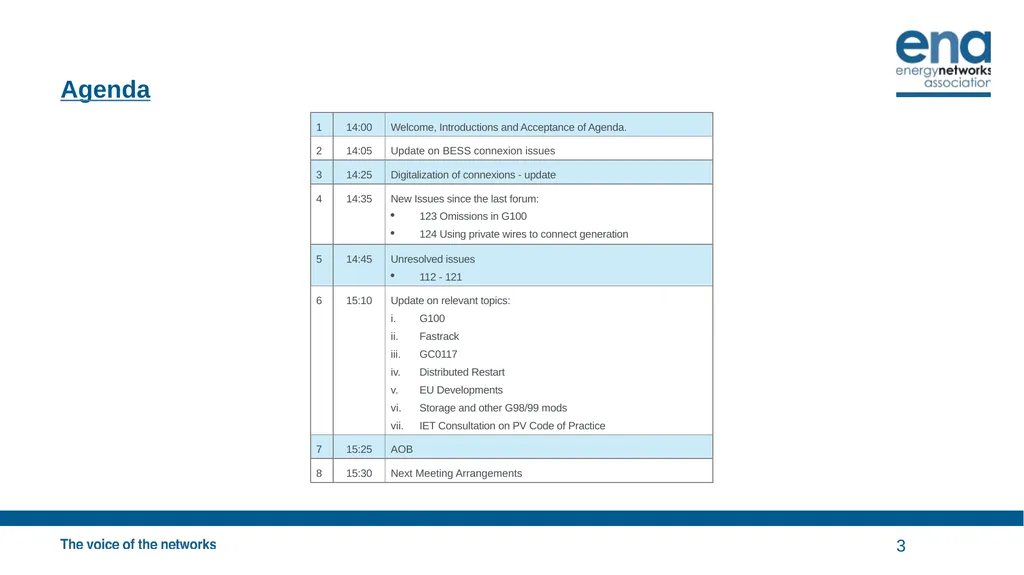
Agenda 3<br>
04
Battery Energy Storage Systems 4<br>
05
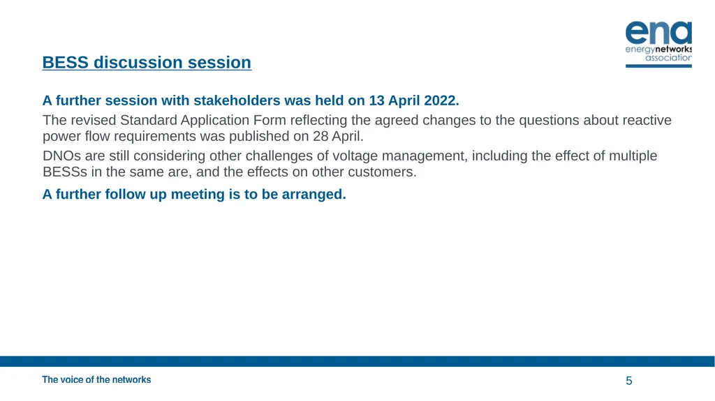
BESS discussion session A further session with stakeholders was held on 13 April 2022.
The revised Standard Application Form reflecting the agreed changes to the questions about reactive power flow requirements was published on 28 April.
DNOs are still considering other challenges of voltage management, including the effect of multiple BESSs in the same are, and the effects on other customers.
A further follow up meeting is to be arranged. 5<br>
The revised Standard Application Form reflecting the agreed changes to the questions about reactive power flow requirements was published on 28 April.
DNOs are still considering other challenges of voltage management, including the effect of multiple BESSs in the same are, and the effects on other customers.
A further follow up meeting is to be arranged. 5<br>
06
Digitalization of Connections 6<br>
07
Digitalization of Connections The Digitalisation of Connections (DoC) Team at the ENA is working through the detailed requirements and technical design to ensure the DoC Tool will work for the ex-PES GB DNOs and also NIE.
The DoC Team is engaging with IT architects, procurement leads, connections leads and lawyers to identify and resolve all of the requirements for data security, process, contracts and liability. 7<br>
The DoC Team is engaging with IT architects, procurement leads, connections leads and lawyers to identify and resolve all of the requirements for data security, process, contracts and liability. 7<br>
08
New Issue 8<br>
09
New Issue - 1 Q G100 Issue 2 - Communication errors: According to G100 any communication failure, longer than 5 seconds, shall set the system to the restricted production mode and only manual intervention will enable setting the system back to the Normal operation mode. From our experience, communication error, longer than 5 seconds are not rare, and the fact that an Installer or the homeowner himself are required to be involved in this process is problematic. In order to avoid this complexity, we can offer to comply with the requirement to detect the communication failure in less than 5 second, to restrict the production to the MEL (max export limit) until the communication error is resolved, and once done to set the system automatically to its Normal operation mode. Using this approach, we will not export any current higher the configured MEL and from the other hand we will not need the Homeowner to set the system back to Normal once the problem is resolved.
A This is a drafting oversight. It was always the intent right from the first discussions on the revised G100 that automatic resetting of communication errors would be allowed.
G100 does not expressly forbid this, but similarly it does not say it is allowed. As this is a simple drafting oversight, the ENA will look to see how the published version can be corrected most propitiously. The proposed redrafting of 4.5.2.2 would be:
4.5.2.2 Communication Failures
The Customer shall be able to reset the CLS back to normal operation immediately in every case when communication has been restored, ie the lockout feature of 4.5.1.3 does not apply. A CLS may be arranged by the Manufacturer or Installer to self-reset from state 3 when state 3 operation is caused solely by communication failures. 9<br>
A This is a drafting oversight. It was always the intent right from the first discussions on the revised G100 that automatic resetting of communication errors would be allowed.
G100 does not expressly forbid this, but similarly it does not say it is allowed. As this is a simple drafting oversight, the ENA will look to see how the published version can be corrected most propitiously. The proposed redrafting of 4.5.2.2 would be:
4.5.2.2 Communication Failures
The Customer shall be able to reset the CLS back to normal operation immediately in every case when communication has been restored, ie the lockout feature of 4.5.1.3 does not apply. A CLS may be arranged by the Manufacturer or Installer to self-reset from state 3 when state 3 operation is caused solely by communication failures. 9<br>
10
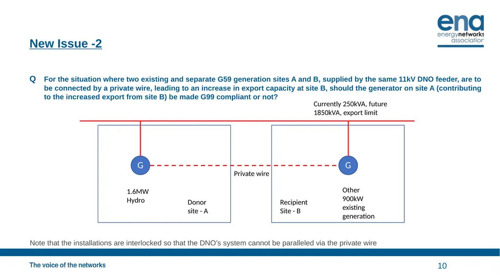
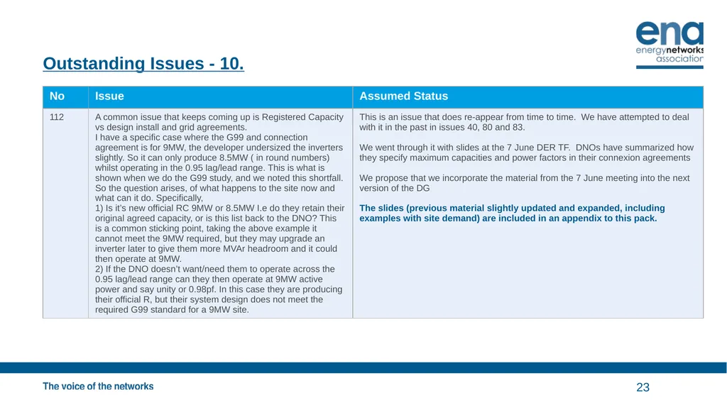
New Issue -2 Q For the situation where two existing and separate G59 generation sites A and B, supplied by the same 11kV DNO feeder, are to be connected by a private wire, leading to an increase in export capacity at site B, should the generator on site A (contributing to the increased export from site B) be made G99 compliant or not?
Note that the installations are interlocked so that the DNO’s system cannot be paralleled via the private wire 10<br>
Note that the installations are interlocked so that the DNO’s system cannot be paralleled via the private wire 10<br>
11
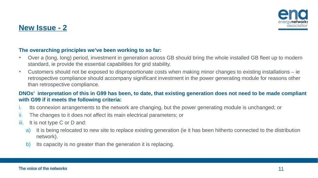
New Issue - 2 The overarching principles we’ve been working to so far:
Over a (long, long) period, investment in generation across GB should bring the whole installed GB fleet up to modern standard, ie provide the essential capabilities for grid stability.
Customers should not be exposed to disproportionate costs when making minor changes to existing installations – ie retrospective compliance should accompany significant investment in the power generating module for reasons other than retrospective compliance.
DNOs’ interpretation of this in G99 has been, to date, that existing generation does not need to be made compliant with G99 if it meets the following criteria:
Its connexion arrangements to the network are changing, but the power generating module is unchanged; or
The changes to it does not affect its main electrical parameters; or
It is not type C or D and:
It is being relocated to new site to replace existing generation (ie it has been hitherto connected to the distribution network).
Its capacity is no greater than the generation it is replacing. 11<br>
Over a (long, long) period, investment in generation across GB should bring the whole installed GB fleet up to modern standard, ie provide the essential capabilities for grid stability.
Customers should not be exposed to disproportionate costs when making minor changes to existing installations – ie retrospective compliance should accompany significant investment in the power generating module for reasons other than retrospective compliance.
DNOs’ interpretation of this in G99 has been, to date, that existing generation does not need to be made compliant with G99 if it meets the following criteria:
Its connexion arrangements to the network are changing, but the power generating module is unchanged; or
The changes to it does not affect its main electrical parameters; or
It is not type C or D and:
It is being relocated to new site to replace existing generation (ie it has been hitherto connected to the distribution network).
Its capacity is no greater than the generation it is replacing. 11<br>
12
New Issue - 2 On this basis, generation at A should be made compliant.
However this is looking at the issue purely from the perspective of installation B (and A) seen from site B’s connexion point.
Given that there is no real effect on the DNOs’ network and no change in the global generation position (from a GB perspective) is this the appropriate treatment? 12<br>
However this is looking at the issue purely from the perspective of installation B (and A) seen from site B’s connexion point.
Given that there is no real effect on the DNOs’ network and no change in the global generation position (from a GB perspective) is this the appropriate treatment? 12<br>
13
Previous Issues 13<br>
14
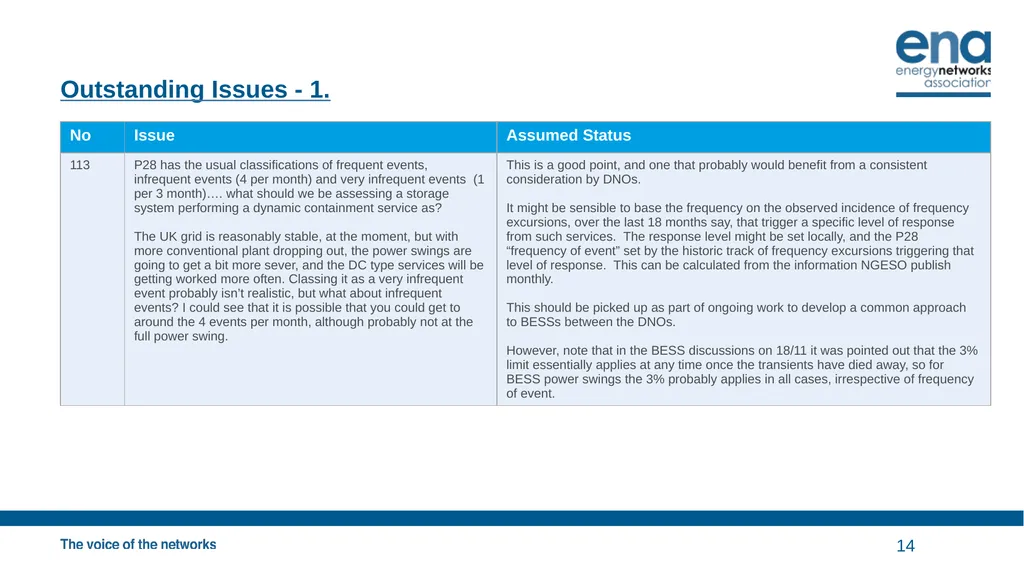
Outstanding Issues - 1. 14<br>
15
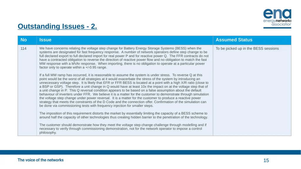
Outstanding Issues - 2. 15<br>
16
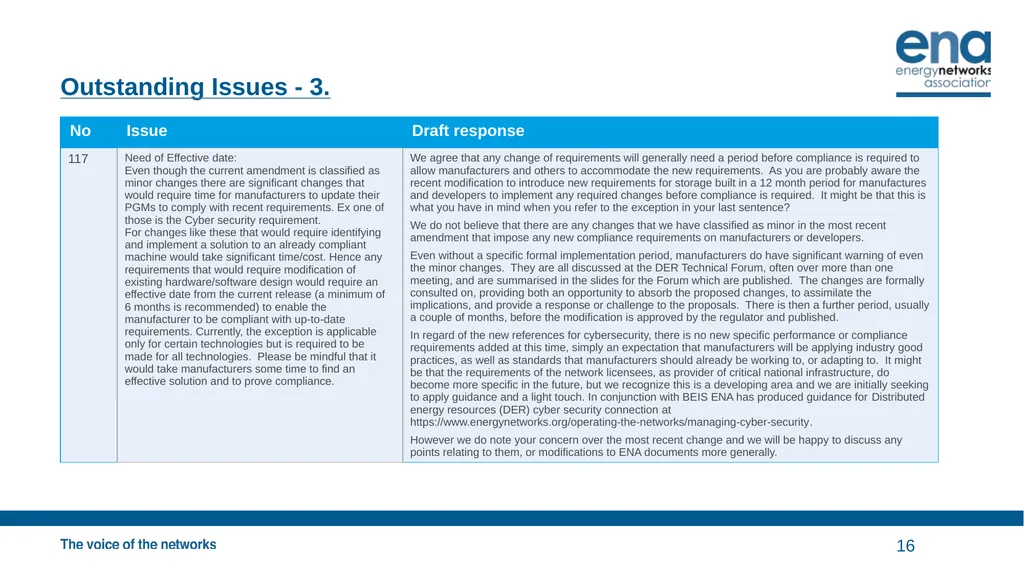
Outstanding Issues - 3. 16<br>
17
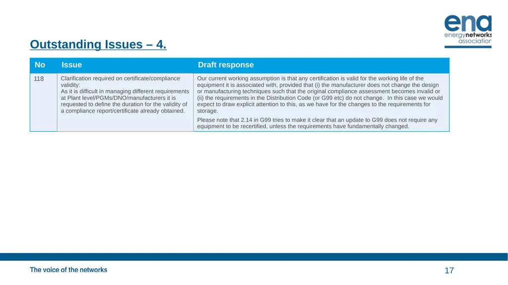
Outstanding Issues – 4. 17<br>
18
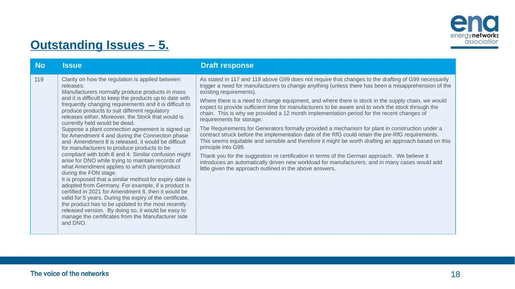
Outstanding Issues – 5. 18<br>
19
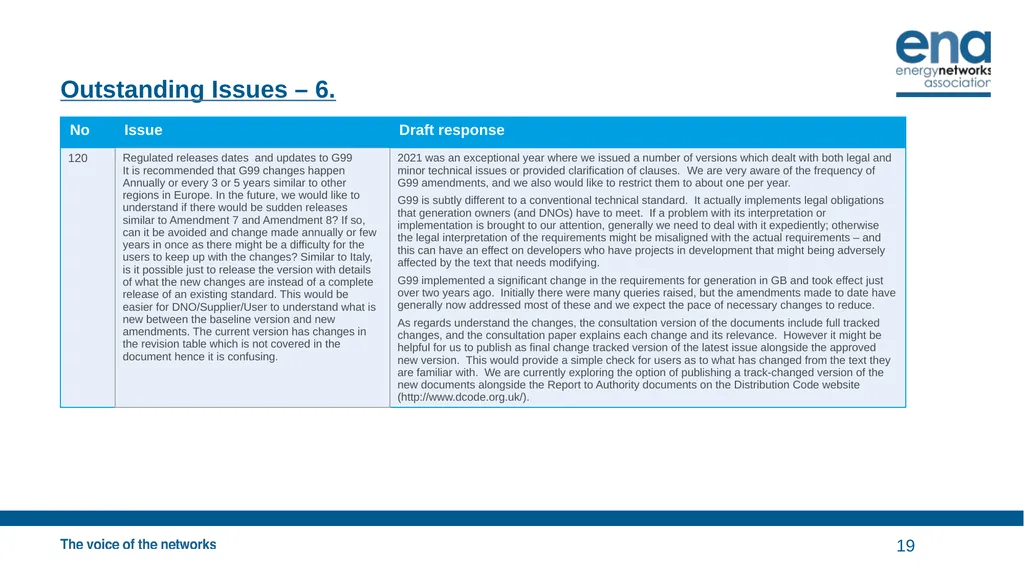
Outstanding Issues – 6. 19<br>
20
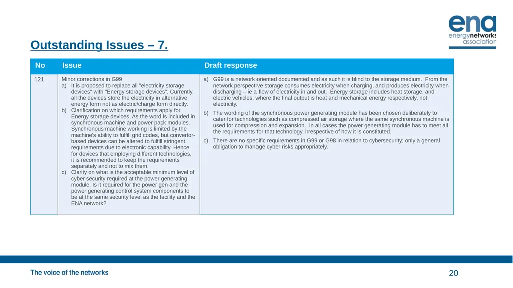
Outstanding Issues – 7. 20<br>
21
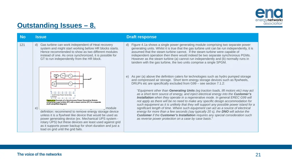
Outstanding Issues – 8. 21<br>
22
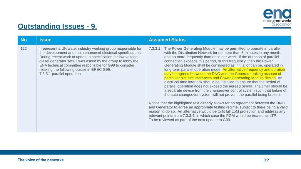
Outstanding Issues - 9. 22<br>
23
Outstanding Issues - 10. 23<br>
24
Update on G100 and Fast Track 24<br>
25
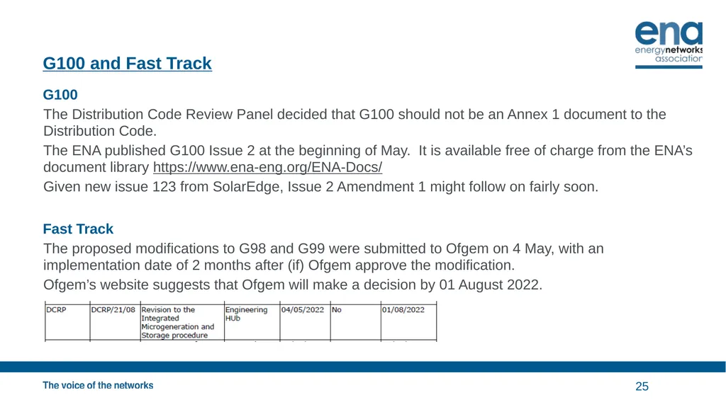
G100 and Fast Track G100
The Distribution Code Review Panel decided that G100 should not be an Annex 1 document to the Distribution Code.
The ENA published G100 Issue 2 at the beginning of May. It is available free of charge from the ENA’s document library https://www.ena-eng.org/ENA-Docs/
Given new issue 123 from SolarEdge, Issue 2 Amendment 1 might follow on fairly soon.
Fast Track
The proposed modifications to G98 and G99 were submitted to Ofgem on 4 May, with an implementation date of 2 months after (if) Ofgem approve the modification.
Ofgem’s website suggests that Ofgem will make a decision by 01 August 2022. 25<br>
The Distribution Code Review Panel decided that G100 should not be an Annex 1 document to the Distribution Code.
The ENA published G100 Issue 2 at the beginning of May. It is available free of charge from the ENA’s document library https://www.ena-eng.org/ENA-Docs/
Given new issue 123 from SolarEdge, Issue 2 Amendment 1 might follow on fairly soon.
Fast Track
The proposed modifications to G98 and G99 were submitted to Ofgem on 4 May, with an implementation date of 2 months after (if) Ofgem approve the modification.
Ofgem’s website suggests that Ofgem will make a decision by 01 August 2022. 25<br>
26
GC0117 26<br>
27
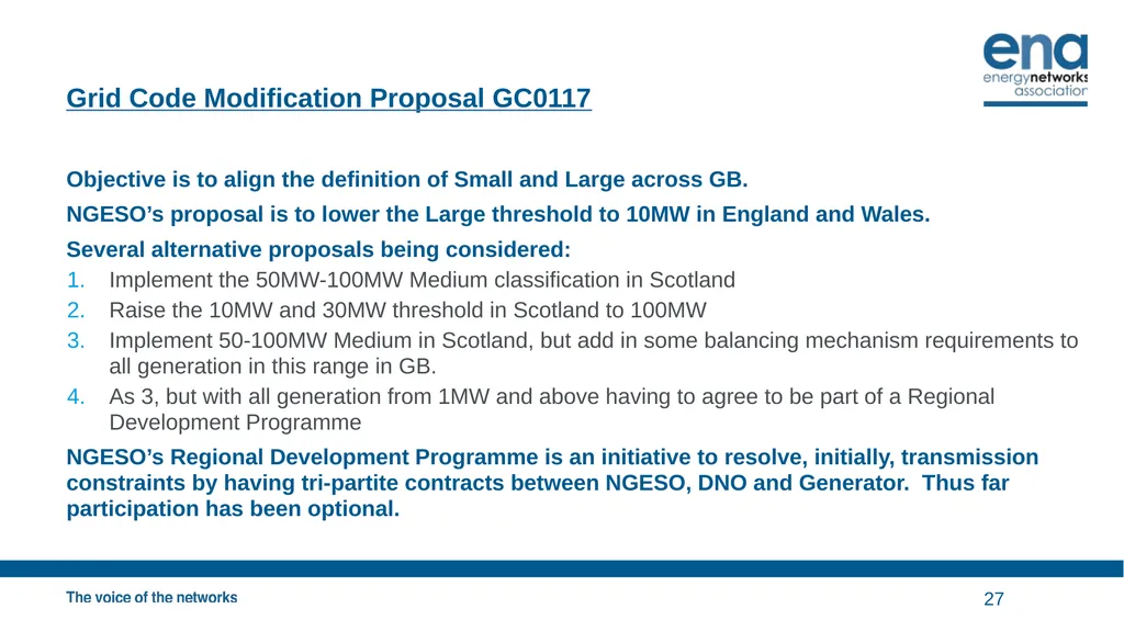
Grid Code Modification Proposal GC0117 Objective is to align the definition of Small and Large across GB.
NGESO’s proposal is to lower the Large threshold to 10MW in England and Wales.
Several alternative proposals being considered:
Implement the 50MW-100MW Medium classification in Scotland
Raise the 10MW and 30MW threshold in Scotland to 100MW
Implement 50-100MW Medium in Scotland, but add in some balancing mechanism requirements to all generation in this range in GB.
As 3, but with all generation from 1MW and above having to agree to be part of a Regional Development Programme
NGESO’s Regional Development Programme is an initiative to resolve, initially, transmission constraints by having tri-partite contracts between NGESO, DNO and Generator. Thus far participation has been optional. 27<br>
NGESO’s proposal is to lower the Large threshold to 10MW in England and Wales.
Several alternative proposals being considered:
Implement the 50MW-100MW Medium classification in Scotland
Raise the 10MW and 30MW threshold in Scotland to 100MW
Implement 50-100MW Medium in Scotland, but add in some balancing mechanism requirements to all generation in this range in GB.
As 3, but with all generation from 1MW and above having to agree to be part of a Regional Development Programme
NGESO’s Regional Development Programme is an initiative to resolve, initially, transmission constraints by having tri-partite contracts between NGESO, DNO and Generator. Thus far participation has been optional. 27<br>
28
GC0117 NGESO initially was arguing for the first of these options, but now it might now favour option 3; ie where the Medium threshold become 50MW in all of GB, but with some additional Balancing Mechanism obligations.
Crucially, all these proposals are now NOT retrospective.
If the proposal remain not retrospective, there could be little or no impact on existing generation – although there would be some changes required for new generation, dependent on which option prevails.
Consultation on the proposals is now expected to be published 07 July 2022. 28<br>
Crucially, all these proposals are now NOT retrospective.
If the proposal remain not retrospective, there could be little or no impact on existing generation – although there would be some changes required for new generation, dependent on which option prevails.
Consultation on the proposals is now expected to be published 07 July 2022. 28<br>
29
Distributed ReStart, GC0148 & GC0156 Emergency and Restoration 29<br>
30
Distributed ReStart Project The GC0148 consultation concluded recently with a strong view from respondents that the complexities of Distributed ReStart should be transferred into GC0156 – Electricity System Restoration Standard.
Therefore GC0148 has no direct impact on G99 and the Distribution Code; but clearly GC0156 is expected to. Work on GC0156 has only just started with the first consultation expected around November this year.
GC0148 does propose new requirements for storage. The Code Administrate Consultation is expected to be in July, with approval by Ofgem expected in the late Autumn. At that time it will be appropriate to consider including these new storage requirements (ie the behaviour as frequency recovers after a dip below the statutory minimum) in G99 and G98. 30<br>
Therefore GC0148 has no direct impact on G99 and the Distribution Code; but clearly GC0156 is expected to. Work on GC0156 has only just started with the first consultation expected around November this year.
GC0148 does propose new requirements for storage. The Code Administrate Consultation is expected to be in July, with approval by Ofgem expected in the late Autumn. At that time it will be appropriate to consider including these new storage requirements (ie the behaviour as frequency recovers after a dip below the statutory minimum) in G99 and G98. 30<br>
31
EU Developments 31<br>
32
EU developments - I ACER is consulting on the policies that should be formally included in the proposed revisions to the Requirements for all Generators and the Demand Connexion Network Codes.
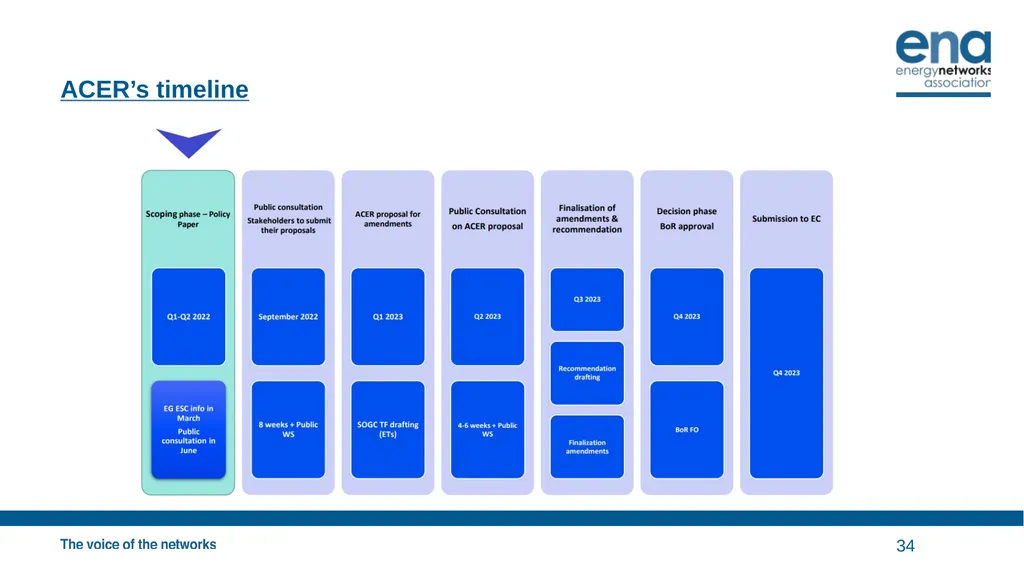
The timeline for the revisions of these two codes is not completely clear – but ACER will running a consultative process on their recommendations for changes, which is intended to be submitted to the European Commission towards the end of 2023 (see a subsequent slide).
ACER’s proposals are:
Modify the requirements for pumped hydro storage units.
Change how the codes apply to sites with mixtures of generation, demand and storage.
Amend how the 110kV threshold for Type D is applied to small generation.
Further harmonization of the technical requirements for Type A PGMs across Europe.
Develop criteria for significant modification, and retrospective compliance.
Formally include electricity storage devices
Revise the requirements for simulation models and compliance monitoring
Make specific requirements (probably just thresholds) for electric vehicles
Specify capabilities for DER where there is a high penetration of DER
Make generation more resilient to severe weather
Recognition of energy communities and the interpretation challenges of the codes for such entities
Revision of DCC application where demand response services and flexibility are provided 32<br>
The timeline for the revisions of these two codes is not completely clear – but ACER will running a consultative process on their recommendations for changes, which is intended to be submitted to the European Commission towards the end of 2023 (see a subsequent slide).
ACER’s proposals are:
Modify the requirements for pumped hydro storage units.
Change how the codes apply to sites with mixtures of generation, demand and storage.
Amend how the 110kV threshold for Type D is applied to small generation.
Further harmonization of the technical requirements for Type A PGMs across Europe.
Develop criteria for significant modification, and retrospective compliance.
Formally include electricity storage devices
Revise the requirements for simulation models and compliance monitoring
Make specific requirements (probably just thresholds) for electric vehicles
Specify capabilities for DER where there is a high penetration of DER
Make generation more resilient to severe weather
Recognition of energy communities and the interpretation challenges of the codes for such entities
Revision of DCC application where demand response services and flexibility are provided 32<br>
33
EU Developments - II The first seven of these pick up work of six expert groups that have reported on the issues.
Item 9 is the subject of a new expert group (see below).
This high level consultation closes on 10 June 2022.
There are three expert groups that have just started, with the intention that are likely to feed into future revisions of the EU Network Codes:
Harmonization of certification and family groupings
Advanced grid services and controls for grids with a high penetration of DER
Connexion issues for offshore systems.
(a) Might be included in item 4 on the previous slide, depending on timing, and similarly (b) ideally will feed into item 9. (c) is unlikely to have any impact on DNOs and their stakeholders.
Although the outcome of all this is unlikely to have any direct effect on the GB arrangements, to the extent the EU market is affected, there could at least be consequential effects in GB. 33<br>
Item 9 is the subject of a new expert group (see below).
This high level consultation closes on 10 June 2022.
There are three expert groups that have just started, with the intention that are likely to feed into future revisions of the EU Network Codes:
Harmonization of certification and family groupings
Advanced grid services and controls for grids with a high penetration of DER
Connexion issues for offshore systems.
(a) Might be included in item 4 on the previous slide, depending on timing, and similarly (b) ideally will feed into item 9. (c) is unlikely to have any impact on DNOs and their stakeholders.
Although the outcome of all this is unlikely to have any direct effect on the GB arrangements, to the extent the EU market is affected, there could at least be consequential effects in GB. 33<br>
34
ACER’s timeline 34<br>
35
Storage, and other mods 35<br>
36
Storage – and further G98/G99 mods From 01 September all storage needs to be compliant with all the mandatory requirements of G98 and G99.
Principally these are:
LFSM-O
FRT for Type B and above
Ability to be controlled by the DNO
Once the Grid Code has been amended, through the GC0148 modification, with the active power response to falling frequency below statutory, G98 and G99 will be amended to make the current optional requirement mandatory, but including the response as frequency recovers.
It is intended to take the opportunity to make a small number of housekeeping amendments. We will circulate our list of these, for comment and additions, in advance of the next DER TF. 36<br>
Principally these are:
LFSM-O
FRT for Type B and above
Ability to be controlled by the DNO
Once the Grid Code has been amended, through the GC0148 modification, with the active power response to falling frequency below statutory, G98 and G99 will be amended to make the current optional requirement mandatory, but including the response as frequency recovers.
It is intended to take the opportunity to make a small number of housekeeping amendments. We will circulate our list of these, for comment and additions, in advance of the next DER TF. 36<br>
37
IET Consultation on PV Code of Practice 37<br>
38
Code of Practice for Grid-connected Solar Photovoltaic Systems From The IET:
The initial draft of the IET’s Code of Practice for Grid-connected Solar Photovoltaic Systems 2nd Edition is now available for public comment. We welcome review and comment from all interested parties.
The Draft for Public Comment (DPC) will be available from 30/05/2022 until 27/06/2022.
For more information, including details for how to access and submit your comments on the DPC document, please visit https://electrical.theiet.org/get-involved/consultations/draft-for-public-consultation-code-of-practice-for-grid-connected-solar-photovoltaic-systems-2nd-edition/ 38<br>
The initial draft of the IET’s Code of Practice for Grid-connected Solar Photovoltaic Systems 2nd Edition is now available for public comment. We welcome review and comment from all interested parties.
The Draft for Public Comment (DPC) will be available from 30/05/2022 until 27/06/2022.
For more information, including details for how to access and submit your comments on the DPC document, please visit https://electrical.theiet.org/get-involved/consultations/draft-for-public-consultation-code-of-practice-for-grid-connected-solar-photovoltaic-systems-2nd-edition/ 38<br>
39
Wrap up: 39<br>
40
Minutes of previous meeting and actions Outstanding matters arising not on the agenda:
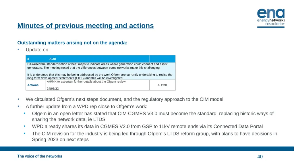
Update on:
We circulated Ofgem’s next steps document, and the regulatory approach to the CIM model.
A further update from a WPD rep close to Ofgem’s work:
Ofgem in an open letter has stated that CIM CGMES V3.0 must become the standard, replacing historic ways of sharing the network data, ie LTDS
WPD already shares its data in CGMES V2.0 from GSP to 11kV remote ends via its Connected Data Portal
The CIM revision for the industry is being led through Ofgem’s LTDS reform group, with plans to have decisions in Spring 2023 on next steps 40<br>
Update on:
We circulated Ofgem’s next steps document, and the regulatory approach to the CIM model.
A further update from a WPD rep close to Ofgem’s work:
Ofgem in an open letter has stated that CIM CGMES V3.0 must become the standard, replacing historic ways of sharing the network data, ie LTDS
WPD already shares its data in CGMES V2.0 from GSP to 11kV remote ends via its Connected Data Portal
The CIM revision for the industry is being led through Ofgem’s LTDS reform group, with plans to have decisions in Spring 2023 on next steps 40<br>
41
AOB and next meeting AOB
None?
Next meeting? 41<br>
None?
Next meeting? 41<br>
42
Appendix – Registered Capacity Examples 42<br>
43
Current Definition: Registered Capacity Was revised in G99/1-6 March 2020
Registered Capacity (Pmax)
The normal maximum Active Power capacity of a either a Power Generating Module (in the case of a Power Park Module, the lesser of the Inverter(s) rating or the rating of the energy source), or of a Power Generating Facility, as declared by the Generator taking into account the Active Power consumed when producing the same and the production of the required Reactive Power at the Connection Point.
Note that NGESO are currently reviewing their view of Registered Capacity as applied to a Power Generating Facility – if they decide to change it (to include some element of netting of demand) then DNOs might follow (as it is really for NGESO and licensing purposes that this definition exists). 43<br>
Registered Capacity (Pmax)
The normal maximum Active Power capacity of a either a Power Generating Module (in the case of a Power Park Module, the lesser of the Inverter(s) rating or the rating of the energy source), or of a Power Generating Facility, as declared by the Generator taking into account the Active Power consumed when producing the same and the production of the required Reactive Power at the Connection Point.
Note that NGESO are currently reviewing their view of Registered Capacity as applied to a Power Generating Facility – if they decide to change it (to include some element of netting of demand) then DNOs might follow (as it is really for NGESO and licensing purposes that this definition exists). 43<br>
44
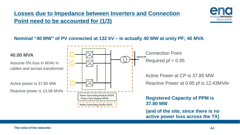
Losses due to Impedance between Inverters and Connection Point need to be accounted for (1/3) Nominal “40 MW” of PV connected at 132 kV – ie actually 40 MW at unity PF; 40 MVA 44 Power Generating Module (PGM) / Power Park Module (PPM) Power Generating Facility (PGF) 132 kV CP Connection Point
Required pf = 0.95
Active Power at CP is 37.80 MW
Reactive Power at 0.95 pf is 12.43MVAr 40.00 MVA
Assume 5% loss in MVAr in cables and across transformer
Active power is 37.80 MW
Reactive power is 13.08 MVAr Registered Capacity of PPM is 37.80 MW
(and of the site, since there is no active power loss across the TX)<br>
Required pf = 0.95
Active Power at CP is 37.80 MW
Reactive Power at 0.95 pf is 12.43MVAr 40.00 MVA
Assume 5% loss in MVAr in cables and across transformer
Active power is 37.80 MW
Reactive power is 13.08 MVAr Registered Capacity of PPM is 37.80 MW
(and of the site, since there is no active power loss across the TX)<br>
45
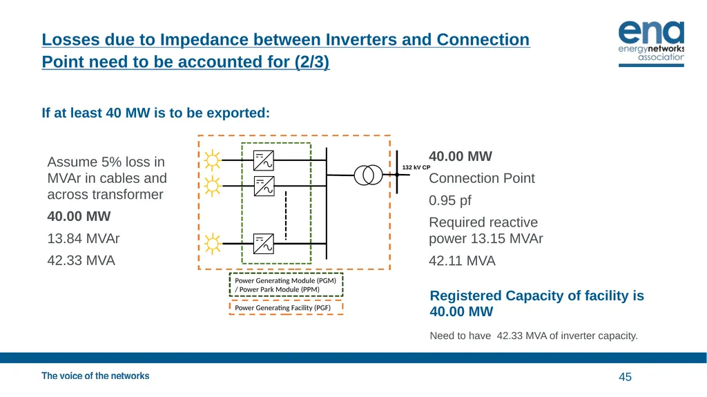
Losses due to Impedance between Inverters and Connection Point need to be accounted for (2/3) If at least 40 MW is to be exported: 45 Power Generating Module (PGM) / Power Park Module (PPM) Power Generating Facility (PGF) 40.00 MW
Connection Point
0.95 pf
Required reactive power 13.15 MVAr
42.11 MVA Assume 5% loss in MVAr in cables and across transformer
40.00 MW
13.84 MVAr
42.33 MVA Registered Capacity of facility is 40.00 MW
Need to have 42.33 MVA of inverter capacity. 132 kV CP<br>
Connection Point
0.95 pf
Required reactive power 13.15 MVAr
42.11 MVA Assume 5% loss in MVAr in cables and across transformer
40.00 MW
13.84 MVAr
42.33 MVA Registered Capacity of facility is 40.00 MW
Need to have 42.33 MVA of inverter capacity. 132 kV CP<br>
46
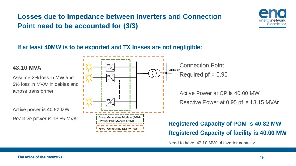
Losses due to Impedance between Inverters and Connection Point need to be accounted for (3/3) If at least 40MW is to be exported and TX losses are not negligible: 46 Power Generating Module (PGM) / Power Park Module (PPM) Power Generating Facility (PGF) 132 kV CP Connection Point
Required pf = 0.95
Active Power at CP is 40.00 MW
Reactive Power at 0.95 pf is 13.15 MVAr 43.10 MVA
Assume 2% loss in MW and 5% loss in MVAr in cables and across transformer
Active power is 40.82 MW
Reactive power is 13.85 MVAr Registered Capacity of PGM is 40.82 MW
Registered Capacity of facility is 40.00 MW
Need to have 43.10 MVA of inverter capacity.<br>
Required pf = 0.95
Active Power at CP is 40.00 MW
Reactive Power at 0.95 pf is 13.15 MVAr 43.10 MVA
Assume 2% loss in MW and 5% loss in MVAr in cables and across transformer
Active power is 40.82 MW
Reactive power is 13.85 MVAr Registered Capacity of PGM is 40.82 MW
Registered Capacity of facility is 40.00 MW
Need to have 43.10 MVA of inverter capacity.<br>
47
How to approach inverter sizing – example 40 MW desired output 40MW of metered export is desired, but this needs to account for the power factor range required, and the reactive loss in the transformer.
If the site expects to run normally at fixed pf, use this pf to determine the MVA required; eg if 40 MW of metered export is required at 0.98 pf leading, then this requires 40.81 MVA of capability. However in order to be compliant with G99 the site also has to be capable of operating at 0.95 pf – which would result in 38.77 MW exported.
The inverter(s) needs to be sized for 42.33 MVA, which of course is 42.33 MW at unity pf.
Assuming no resistive losses between the inverter(s) and the connexion point, the Registered Capacity of the Power Generating Module is 38.77 MW.
However the maximum export capacity can be agreed to be 40.81 MVA at 0.98 pf (leading). This will allow export of 40 MW at the required power factor.
If there are auxiliary supplies and other reactive (or real) losses on the Generator’s system these will need to be factored in and the inverter(s) upsized if the metered output is to be maintained. 47<br>
If the site expects to run normally at fixed pf, use this pf to determine the MVA required; eg if 40 MW of metered export is required at 0.98 pf leading, then this requires 40.81 MVA of capability. However in order to be compliant with G99 the site also has to be capable of operating at 0.95 pf – which would result in 38.77 MW exported.
The inverter(s) needs to be sized for 42.33 MVA, which of course is 42.33 MW at unity pf.
Assuming no resistive losses between the inverter(s) and the connexion point, the Registered Capacity of the Power Generating Module is 38.77 MW.
However the maximum export capacity can be agreed to be 40.81 MVA at 0.98 pf (leading). This will allow export of 40 MW at the required power factor.
If there are auxiliary supplies and other reactive (or real) losses on the Generator’s system these will need to be factored in and the inverter(s) upsized if the metered output is to be maintained. 47<br>
48
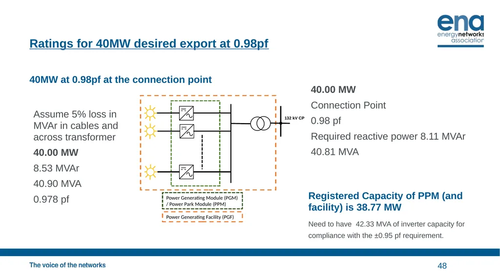
Ratings for 40MW desired export at 0.98pf 40MW at 0.98pf at the connection point 48 Power Generating Module (PGM) / Power Park Module (PPM) Power Generating Facility (PGF) 40.00 MW
Connection Point
0.98 pf
Required reactive power 8.11 MVAr
40.81 MVA Assume 5% loss in MVAr in cables and across transformer
40.00 MW
8.53 MVAr
40.90 MVA
0.978 pf Registered Capacity of PPM (and facility) is 38.77 MW
Need to have 42.33 MVA of inverter capacity for compliance with the ±0.95 pf requirement. 132 kV CP<br>
Connection Point
0.98 pf
Required reactive power 8.11 MVAr
40.81 MVA Assume 5% loss in MVAr in cables and across transformer
40.00 MW
8.53 MVAr
40.90 MVA
0.978 pf Registered Capacity of PPM (and facility) is 38.77 MW
Need to have 42.33 MVA of inverter capacity for compliance with the ±0.95 pf requirement. 132 kV CP<br>
49
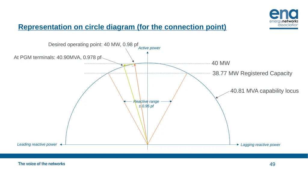
Representation on circle diagram (for the connection point) 49 40 MW 38.77 MW Registered Capacity 40.81 MVA capability locus At PGM terminals: 40.90MVA, 0.978 pf Active power Lagging reactive power Leading reactive power Reactive range
± 0.95 pf Desired operating point: 40 MW, 0.98 pf<br>
50
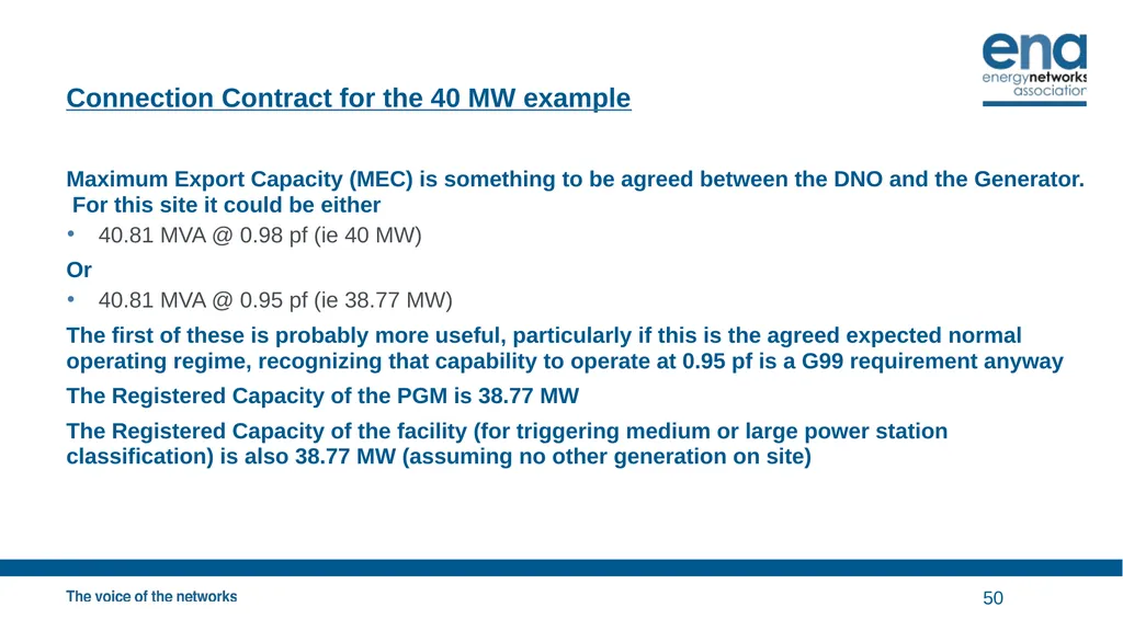
Connection Contract for the 40 MW example Maximum Export Capacity (MEC) is something to be agreed between the DNO and the Generator. For this site it could be either
40.81 MVA @ 0.98 pf (ie 40 MW)
Or
40.81 MVA @ 0.95 pf (ie 38.77 MW)
The first of these is probably more useful, particularly if this is the agreed expected normal operating regime, recognizing that capability to operate at 0.95 pf is a G99 requirement anyway
The Registered Capacity of the PGM is 38.77 MW
The Registered Capacity of the facility (for triggering medium or large power station classification) is also 38.77 MW (assuming no other generation on site) 50<br>
40.81 MVA @ 0.98 pf (ie 40 MW)
Or
40.81 MVA @ 0.95 pf (ie 38.77 MW)
The first of these is probably more useful, particularly if this is the agreed expected normal operating regime, recognizing that capability to operate at 0.95 pf is a G99 requirement anyway
The Registered Capacity of the PGM is 38.77 MW
The Registered Capacity of the facility (for triggering medium or large power station classification) is also 38.77 MW (assuming no other generation on site) 50<br>
51
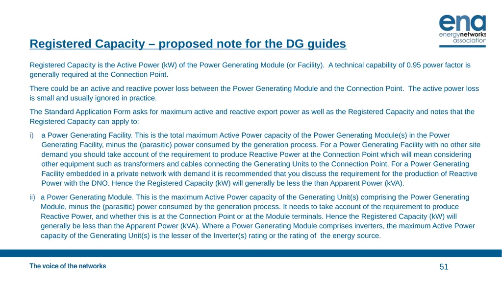
Registered Capacity – proposed note for the DG guides Registered Capacity is the Active Power (kW) of the Power Generating Module (or Facility). A technical capability of 0.95 power factor is generally required at the Connection Point.
There could be an active and reactive power loss between the Power Generating Module and the Connection Point. The active power loss is small and usually ignored in practice.
The Standard Application Form asks for maximum active and reactive export power as well as the Registered Capacity and notes that the Registered Capacity can apply to:
a Power Generating Facility. This is the total maximum Active Power capacity of the Power Generating Module(s) in the Power Generating Facility, minus the (parasitic) power consumed by the generation process. For a Power Generating Facility with no other site demand you should take account of the requirement to produce Reactive Power at the Connection Point which will mean considering other equipment such as transformers and cables connecting the Generating Units to the Connection Point. For a Power Generating Facility embedded in a private network with demand it is recommended that you discuss the requirement for the production of Reactive Power with the DNO. Hence the Registered Capacity (kW) will generally be less the than Apparent Power (kVA).
a Power Generating Module. This is the maximum Active Power capacity of the Generating Unit(s) comprising the Power Generating Module, minus the (parasitic) power consumed by the generation process. It needs to take account of the requirement to produce Reactive Power, and whether this is at the Connection Point or at the Module terminals. Hence the Registered Capacity (kW) will generally be less than the Apparent Power (kVA). Where a Power Generating Module comprises inverters, the maximum Active Power capacity of the Generating Unit(s) is the lesser of the Inverter(s) rating or the rating of the energy source. 51<br>
There could be an active and reactive power loss between the Power Generating Module and the Connection Point. The active power loss is small and usually ignored in practice.
The Standard Application Form asks for maximum active and reactive export power as well as the Registered Capacity and notes that the Registered Capacity can apply to:
a Power Generating Facility. This is the total maximum Active Power capacity of the Power Generating Module(s) in the Power Generating Facility, minus the (parasitic) power consumed by the generation process. For a Power Generating Facility with no other site demand you should take account of the requirement to produce Reactive Power at the Connection Point which will mean considering other equipment such as transformers and cables connecting the Generating Units to the Connection Point. For a Power Generating Facility embedded in a private network with demand it is recommended that you discuss the requirement for the production of Reactive Power with the DNO. Hence the Registered Capacity (kW) will generally be less the than Apparent Power (kVA).
a Power Generating Module. This is the maximum Active Power capacity of the Generating Unit(s) comprising the Power Generating Module, minus the (parasitic) power consumed by the generation process. It needs to take account of the requirement to produce Reactive Power, and whether this is at the Connection Point or at the Module terminals. Hence the Registered Capacity (kW) will generally be less than the Apparent Power (kVA). Where a Power Generating Module comprises inverters, the maximum Active Power capacity of the Generating Unit(s) is the lesser of the Inverter(s) rating or the rating of the energy source. 51<br>
52
Examples of RCs of PGMs and Facilities, including where there is demand in the Facility. 52<br>
53
Representative examples In the following slides, there are several generators, storage, and loads. These slides are identical to those tabled at the 24 February DER Technical Forum, but typical plant sizes have been used instead of non-specific sizes.
The sizes are arbitrary but picked to illustrate possibilities.
The possibilities are really infinite, so these examples are far from exhaustive. 53<br>
The sizes are arbitrary but picked to illustrate possibilities.
The possibilities are really infinite, so these examples are far from exhaustive. 53<br>
54
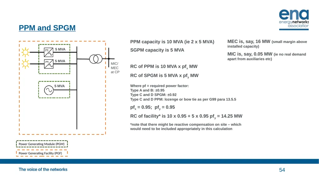
PPM and SPGM 54 Power Generating Module (PGM) Power Generating Facility (PGF) PPM capacity is 10 MVA (ie 2 x 5 MVA)
SGPM capacity is 5 MVA
RC of PPM is 10 MVA x pfx MW
RC of SPGM is 5 MVA x pfy MW
Where pf = required power factor:
Type A and B: ±0.95
Type C and D SPGM: ±0.92
Type C and D PPM: lozenge or bow tie as per G99 para 13.5.5
pfx = 0.95; pfy = 0.95
RC of facility* is 10 x 0.95 + 5 x 0.95 pfy = 14.25 MW
*note that there might be reactive compensation on site – which would need to be included appropriately in this calculation MEC is, say, 16 MW (small margin above installed capacity)
MIC is, say, 0.05 MW (ie no real demand apart from auxiliaries etc) 5 MVA 5 MVA 5 MVA MIC/ MEC at CP<br>
SGPM capacity is 5 MVA
RC of PPM is 10 MVA x pfx MW
RC of SPGM is 5 MVA x pfy MW
Where pf = required power factor:
Type A and B: ±0.95
Type C and D SPGM: ±0.92
Type C and D PPM: lozenge or bow tie as per G99 para 13.5.5
pfx = 0.95; pfy = 0.95
RC of facility* is 10 x 0.95 + 5 x 0.95 pfy = 14.25 MW
*note that there might be reactive compensation on site – which would need to be included appropriately in this calculation MEC is, say, 16 MW (small margin above installed capacity)
MIC is, say, 0.05 MW (ie no real demand apart from auxiliaries etc) 5 MVA 5 MVA 5 MVA MIC/ MEC at CP<br>
55
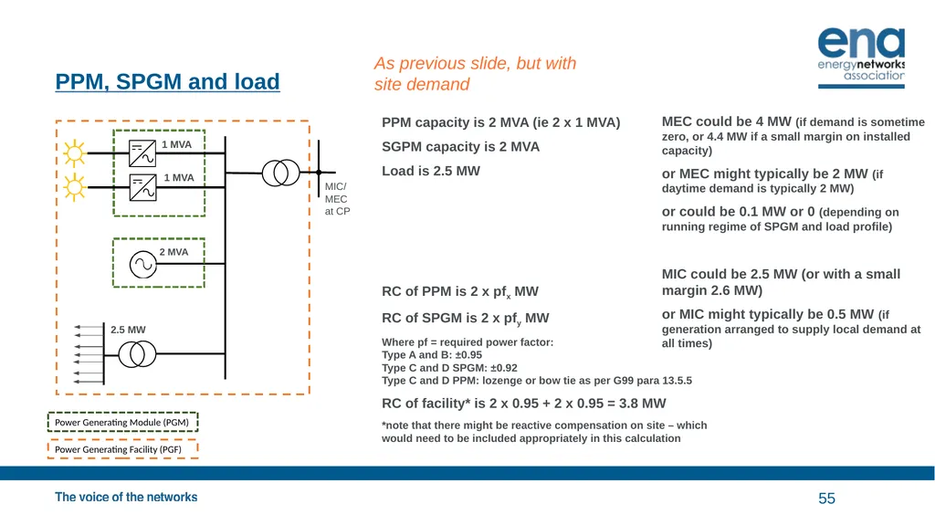
PPM, SPGM and load 55 Power Generating Module (PGM) Power Generating Facility (PGF) PPM capacity is 2 MVA (ie 2 x 1 MVA)
SGPM capacity is 2 MVA
Load is 2.5 MW
RC of PPM is 2 x pfx MW
RC of SPGM is 2 x pfy MW
Where pf = required power factor:
Type A and B: ±0.95
Type C and D SPGM: ±0.92
Type C and D PPM: lozenge or bow tie as per G99 para 13.5.5
RC of facility* is 2 x 0.95 + 2 x 0.95 = 3.8 MW
*note that there might be reactive compensation on site – which would need to be included appropriately in this calculation MEC could be 4 MW (if demand is sometime zero, or 4.4 MW if a small margin on installed capacity)
or MEC might typically be 2 MW (if daytime demand is typically 2 MW)
or could be 0.1 MW or 0 (depending on running regime of SPGM and load profile)
MIC could be 2.5 MW (or with a small margin 2.6 MW)
or MIC might typically be 0.5 MW (if generation arranged to supply local demand at all times) 2 MVA 1 MVA 2.5 MW MIC/ MEC at CP As previous slide, but with site demand 1 MVA<br>
SGPM capacity is 2 MVA
Load is 2.5 MW
RC of PPM is 2 x pfx MW
RC of SPGM is 2 x pfy MW
Where pf = required power factor:
Type A and B: ±0.95
Type C and D SPGM: ±0.92
Type C and D PPM: lozenge or bow tie as per G99 para 13.5.5
RC of facility* is 2 x 0.95 + 2 x 0.95 = 3.8 MW
*note that there might be reactive compensation on site – which would need to be included appropriately in this calculation MEC could be 4 MW (if demand is sometime zero, or 4.4 MW if a small margin on installed capacity)
or MEC might typically be 2 MW (if daytime demand is typically 2 MW)
or could be 0.1 MW or 0 (depending on running regime of SPGM and load profile)
MIC could be 2.5 MW (or with a small margin 2.6 MW)
or MIC might typically be 0.5 MW (if generation arranged to supply local demand at all times) 2 MVA 1 MVA 2.5 MW MIC/ MEC at CP As previous slide, but with site demand 1 MVA<br>
56
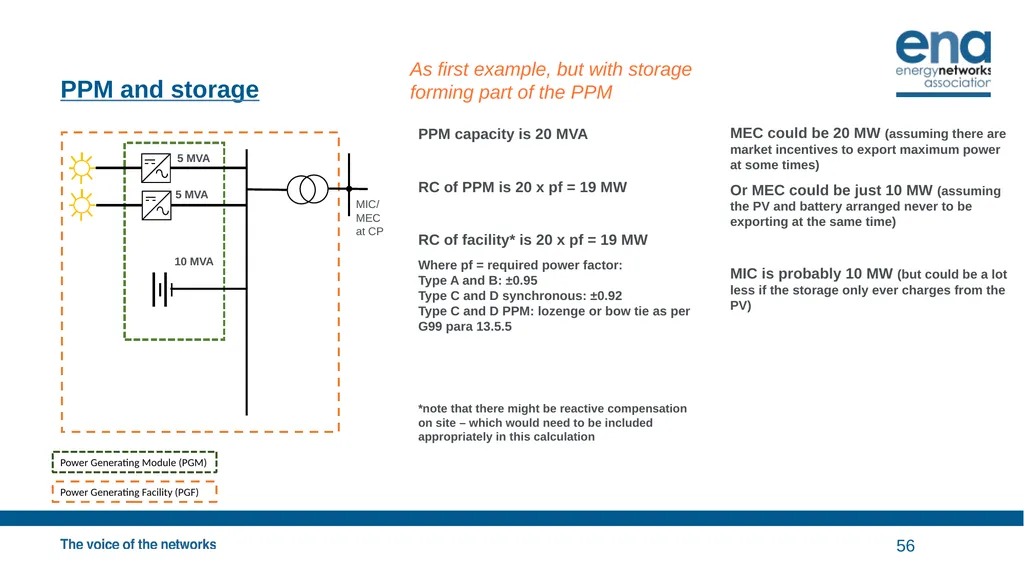
PPM and storage 56 Power Generating Module (PGM) Power Generating Facility (PGF) PPM capacity is 20 MVA
RC of PPM is 20 x pf = 19 MW
RC of facility* is 20 x pf = 19 MW
Where pf = required power factor:
Type A and B: ±0.95
Type C and D synchronous: ±0.92
Type C and D PPM: lozenge or bow tie as per G99 para 13.5.5
*note that there might be reactive compensation on site – which would need to be included appropriately in this calculation MEC could be 20 MW (assuming there are market incentives to export maximum power at some times)
Or MEC could be just 10 MW (assuming the PV and battery arranged never to be exporting at the same time)
MIC is probably 10 MW (but could be a lot less if the storage only ever charges from the PV) 5 MVA MIC/ MEC at CP As first example, but with storage forming part of the PPM 5 MVA 10 MVA<br>
RC of PPM is 20 x pf = 19 MW
RC of facility* is 20 x pf = 19 MW
Where pf = required power factor:
Type A and B: ±0.95
Type C and D synchronous: ±0.92
Type C and D PPM: lozenge or bow tie as per G99 para 13.5.5
*note that there might be reactive compensation on site – which would need to be included appropriately in this calculation MEC could be 20 MW (assuming there are market incentives to export maximum power at some times)
Or MEC could be just 10 MW (assuming the PV and battery arranged never to be exporting at the same time)
MIC is probably 10 MW (but could be a lot less if the storage only ever charges from the PV) 5 MVA MIC/ MEC at CP As first example, but with storage forming part of the PPM 5 MVA 10 MVA<br>
57
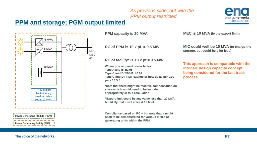
PPM and storage; PGM output limited 57 Power Generating Module (PGM) Power Generating Facility (PGF) PPM capacity is 20 MVA
RC of PPM is 10 x pf = 9.5 MW
RC of facility* is 10 x pf = 9.5 MW
Where pf = required power factor:
Type A and B: ±0.95
Type C and D SPGM: ±0.92
Type C and D PPM: lozenge or bow tie as per G99 para 13.5.5
*note that there might be reactive compensation on site – which would need to be included appropriately in this calculation
† Export limit could be any value less than 20 MVA, but likely that it will at least 10 MVA
Compliance based on RC – but note that it might need to be demonstrated for various mixes of generating units within the PPM MEC is 10 MVA (ie the export limit)
MIC could well be 10 MVA (to charge the storage, but could be a lot less)
This approach is comparable with the intrinsic design capacity concept being considered for the fast track process. MIC/ MEC at CP PPM export limitation, eg overload relay, set at 10 MVA† As previous slide, but with the PPM output restricted 5 MVA 5 MVA 10 MVA<br>
RC of PPM is 10 x pf = 9.5 MW
RC of facility* is 10 x pf = 9.5 MW
Where pf = required power factor:
Type A and B: ±0.95
Type C and D SPGM: ±0.92
Type C and D PPM: lozenge or bow tie as per G99 para 13.5.5
*note that there might be reactive compensation on site – which would need to be included appropriately in this calculation
† Export limit could be any value less than 20 MVA, but likely that it will at least 10 MVA
Compliance based on RC – but note that it might need to be demonstrated for various mixes of generating units within the PPM MEC is 10 MVA (ie the export limit)
MIC could well be 10 MVA (to charge the storage, but could be a lot less)
This approach is comparable with the intrinsic design capacity concept being considered for the fast track process. MIC/ MEC at CP PPM export limitation, eg overload relay, set at 10 MVA† As previous slide, but with the PPM output restricted 5 MVA 5 MVA 10 MVA<br>
58
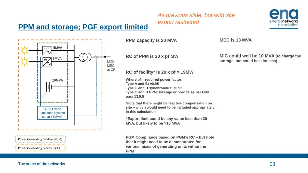
PPM and storage; PGF export limited 58 Power Generating Module (PGM) Power Generating Facility (PGF) PPM capacity is 20 MVA
RC of PPM is 20 x pf MW
RC of facility* is 20 x pf = 19MW
Where pf = required power factor:
Type A and B: ±0.95
Type C and D synchronous: ±0.92
Type C and D PPM: lozenge or bow tie as per G99 para 13.5.5
*note that there might be reactive compensation on site – which would need to be included appropriately in this calculation
† Export limit could be any value less than 20 MVA, but likely to be >10 MVA
PGM Compliance based on PGM’s RC – but note that it might need to be demonstrated for various mixes of generating units within the PPM MEC is 13 MVA
MIC could well be 10 MVA (to charge the storage, but could be a lot less) MIC/ MEC at CP G100 Export Limitation System set at 13MVA† As previous slide, but with site export restricted 5MVA 5MVA 10MVA<br>
RC of PPM is 20 x pf MW
RC of facility* is 20 x pf = 19MW
Where pf = required power factor:
Type A and B: ±0.95
Type C and D synchronous: ±0.92
Type C and D PPM: lozenge or bow tie as per G99 para 13.5.5
*note that there might be reactive compensation on site – which would need to be included appropriately in this calculation
† Export limit could be any value less than 20 MVA, but likely to be >10 MVA
PGM Compliance based on PGM’s RC – but note that it might need to be demonstrated for various mixes of generating units within the PPM MEC is 13 MVA
MIC could well be 10 MVA (to charge the storage, but could be a lot less) MIC/ MEC at CP G100 Export Limitation System set at 13MVA† As previous slide, but with site export restricted 5MVA 5MVA 10MVA<br>
59
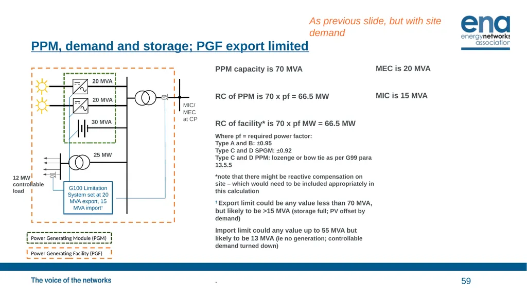
PPM, demand and storage; PGF export limited 59 Power Generating Module (PGM) Power Generating Facility (PGF) PPM capacity is 70 MVA
RC of PPM is 70 x pf = 66.5 MW
RC of facility* is 70 x pf MW = 66.5 MW
Where pf = required power factor:
Type A and B: ±0.95
Type C and D SPGM: ±0.92
Type C and D PPM: lozenge or bow tie as per G99 para 13.5.5
*note that there might be reactive compensation on site – which would need to be included appropriately in this calculation
† Export limit could be any value less than 70 MVA, but likely to be >15 MVA (storage full; PV offset by demand)
Import limit could any value up to 55 MVA but likely to be 13 MVA (ie no generation; controllable demand turned down)
. MEC is 20 MVA
MIC is 15 MVA 30 MVA MIC/ MEC at CP G100 Limitation System set at 20 MVA export, 15 MVA import† 12 MW
controllable load As previous slide, but with site demand 20 MVA 20 MVA 25 MW<br>
RC of PPM is 70 x pf = 66.5 MW
RC of facility* is 70 x pf MW = 66.5 MW
Where pf = required power factor:
Type A and B: ±0.95
Type C and D SPGM: ±0.92
Type C and D PPM: lozenge or bow tie as per G99 para 13.5.5
*note that there might be reactive compensation on site – which would need to be included appropriately in this calculation
† Export limit could be any value less than 70 MVA, but likely to be >15 MVA (storage full; PV offset by demand)
Import limit could any value up to 55 MVA but likely to be 13 MVA (ie no generation; controllable demand turned down)
. MEC is 20 MVA
MIC is 15 MVA 30 MVA MIC/ MEC at CP G100 Limitation System set at 20 MVA export, 15 MVA import† 12 MW
controllable load As previous slide, but with site demand 20 MVA 20 MVA 25 MW<br>
60
© ENA 2020<br>