
Distribution System Grounding Dr. Zhaoyu Wang 1113
NS
Published · 27 slides · 0 views

1 / 1

Description
Distribution System Grounding Dr. Zhaoyu Wang 1113 Coover Hall, Ames, IA wzyiastate.edu ECpE Department Distribution System Grounding 2 ECpE Department Acknowledgement: The slides are developed based in part on Electric Power and Energy
Related Topics
Share
Embed code
Download this presentation From Below
"Distribution System Grounding Dr. Zhaoyu Wang 1113" is the property of its rightful owner. Permission is granted to download and print the materials on this website for personal, non-commercial use only, and to display it on your personal computer provided you do not modify the materials and that you retain all copyright notices contained in the materials. By downloading content from our website, you accept the terms of this agreement.
Presentation Transcript
01
Distribution System Grounding Dr. Zhaoyu Wang
1113 Coover Hall, Ames, IA
wzy@iastate.edu ECpE Department<br>
1113 Coover Hall, Ames, IA
wzy@iastate.edu ECpE Department<br>
02
Distribution System Grounding 2 ECpE Department Acknowledgement:
The slides are developed based in part on Electric Power and Energy Distribution Systems, Models, Methods and Applications, Subrahmanyan S. Venkata, Anil Pahwa, IEEE Press & Wiley, 2022<br>
The slides are developed based in part on Electric Power and Energy Distribution Systems, Models, Methods and Applications, Subrahmanyan S. Venkata, Anil Pahwa, IEEE Press & Wiley, 2022<br>
03
1 Basics of Grounding Need for Grounding:
Grounding is a mechanism to protect distribution equipment and people under normal operating conditions, abnormal operational (overcurrent and overvoltage) responses, and hazardous conditions such as shocks.
Grounding is necessary to assure correct operation of electrical devices, to assure safety during normal or fault conditions, to stabilize voltages during transient conditions, and to dissipate energy associated with lightning strokes.
Good system grounding provides the path for normal load and fault currents while maintaining load and controls temporary overvoltage. Good equipment grounding ensures personnel safety. 3 ECpE Department<br>
Grounding is a mechanism to protect distribution equipment and people under normal operating conditions, abnormal operational (overcurrent and overvoltage) responses, and hazardous conditions such as shocks.
Grounding is necessary to assure correct operation of electrical devices, to assure safety during normal or fault conditions, to stabilize voltages during transient conditions, and to dissipate energy associated with lightning strokes.
Good system grounding provides the path for normal load and fault currents while maintaining load and controls temporary overvoltage. Good equipment grounding ensures personnel safety. 3 ECpE Department<br>
04
1 Basics of Grounding Approaches for Grounding:
Most North American distribution systems have a neutral that acts as a return conductor and as an equipment safety ground. It is recommended to ground the neutral at various strategic locations in distribution substations, overhead lines and underground cables, distribution transformers, and all loads.
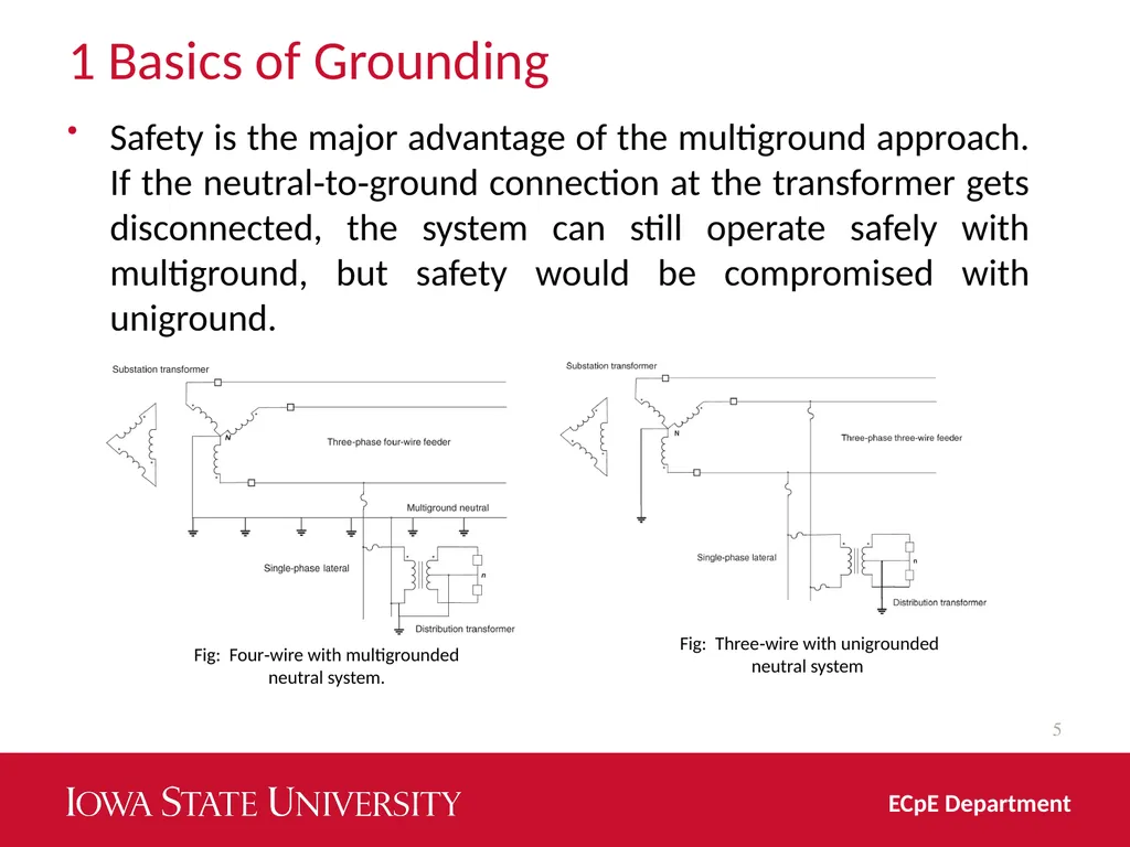
Four‐wire with multigrounded neutral system (most common type followed in the United States)
Three‐wire with unigrounded neutral system (neutral is grounded only at the substation and the distribution transformers.)
Three‐wire with ungrounded system
Three‐wire ungrounded delta‐connected system 4 ECpE Department<br>
Most North American distribution systems have a neutral that acts as a return conductor and as an equipment safety ground. It is recommended to ground the neutral at various strategic locations in distribution substations, overhead lines and underground cables, distribution transformers, and all loads.
Four‐wire with multigrounded neutral system (most common type followed in the United States)
Three‐wire with unigrounded neutral system (neutral is grounded only at the substation and the distribution transformers.)
Three‐wire with ungrounded system
Three‐wire ungrounded delta‐connected system 4 ECpE Department<br>
05
1 Basics of Grounding 5 ECpE Department Safety is the major advantage of the multiground approach. If the neutral‐to‐ground connection at the transformer gets disconnected, the system can still operate safely with multiground, but safety would be compromised with uniground. Fig: Four‐wire with multigrounded neutral system. Fig: Three‐wire with unigrounded neutral system<br>
06
1 Basics of Grounding 6 ECpE Department Four‐wire systems are superior to three‐wire systems for serving single‐phase loads and are predominant in North America.
In addition to safety, it is cheaper to build the system because a single cable can be used for underground single‐phase load, and single‐phase overhead lines are less costly.
The distribution transformers with this configuration need only one bushing, one surge arrester, and one fuse on the live side.<br>
In addition to safety, it is cheaper to build the system because a single cable can be used for underground single‐phase load, and single‐phase overhead lines are less costly.
The distribution transformers with this configuration need only one bushing, one surge arrester, and one fuse on the live side.<br>
07
1 Basics of Grounding Effects of Grounding on System Models:
Neutral grounding, the system frequency and soil resistivity impact modeling of the distribution system components.
Specifically, frequency and soil resistivity have a profound effect on online parameters. For example, in Chapter 3, while developing the models for overhead distribution feeders using Carson's equations, we assumed that the neutral is grounded at multiple locations, which resulted in voltage drop across the neutral conductor to be zero because grounding made a significant portion of the current to flow through the ground.
In addition, the impedance values depend on the frequency and the soil resistivity. 7 ECpE Department<br>
Neutral grounding, the system frequency and soil resistivity impact modeling of the distribution system components.
Specifically, frequency and soil resistivity have a profound effect on online parameters. For example, in Chapter 3, while developing the models for overhead distribution feeders using Carson's equations, we assumed that the neutral is grounded at multiple locations, which resulted in voltage drop across the neutral conductor to be zero because grounding made a significant portion of the current to flow through the ground.
In addition, the impedance values depend on the frequency and the soil resistivity. 7 ECpE Department<br>
08
2 Neutral Grounding 2.1 Neutral Shift Due to Ground Faults:
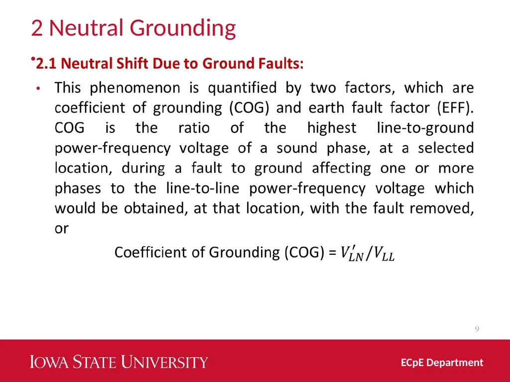
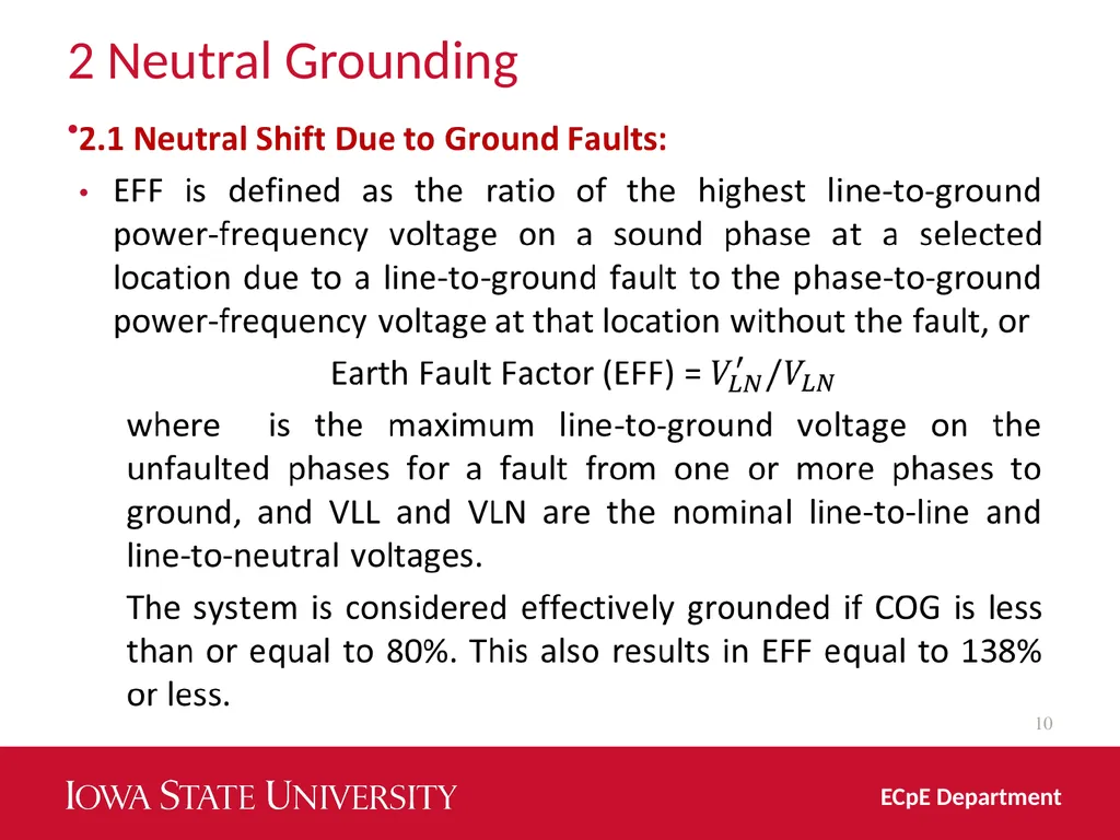
A single‐line‐to‐ground fault in distribution systems causes a shift in the potential of the ground at the fault location. The level of the shift is a function of grounding used in the system .
In ungrounded systems, the line‐to‐ground voltage on unfaulted phases increases to the line‐to‐line voltage or 1.73 per unit.
In a system with perfectly grounded neutral, there is no shift in the neutral voltage. However, in a system with multiground neutral, the voltage can rise to 1.3 per unit. 8 ECpE Department<br>
A single‐line‐to‐ground fault in distribution systems causes a shift in the potential of the ground at the fault location. The level of the shift is a function of grounding used in the system .
In ungrounded systems, the line‐to‐ground voltage on unfaulted phases increases to the line‐to‐line voltage or 1.73 per unit.
In a system with perfectly grounded neutral, there is no shift in the neutral voltage. However, in a system with multiground neutral, the voltage can rise to 1.3 per unit. 8 ECpE Department<br>
09
2 Neutral Grounding 9 ECpE Department<br>
10
2 Neutral Grounding 10 ECpE Department<br>
11
2 Neutral Grounding 2.2 Types of Neutral Grounding:
A resistance or reactance is used between the neutral of the substation transformer and the ground to reduce the level of ground fault currents.
In the United States, typically reactance is used to ground the neutral on the low‐voltage side of the delta‐wye‐connected distribution substation transformers.
However, this also reduces the effectiveness of grounding, which results in higher voltages on the unfaulted phases.
Therefore, selection of the reactor for neutral grounding must be carefully evaluated by considering the trade‐off between the decrease in fault current and increase in voltage on the unfaulted phases. 11 ECpE Department<br>
A resistance or reactance is used between the neutral of the substation transformer and the ground to reduce the level of ground fault currents.
In the United States, typically reactance is used to ground the neutral on the low‐voltage side of the delta‐wye‐connected distribution substation transformers.
However, this also reduces the effectiveness of grounding, which results in higher voltages on the unfaulted phases.
Therefore, selection of the reactor for neutral grounding must be carefully evaluated by considering the trade‐off between the decrease in fault current and increase in voltage on the unfaulted phases. 11 ECpE Department<br>
12
2 Neutral Grounding 2.3 Standards for Neutral Grounding:
ANSI/IEEE Standards 80 “IEEE Guide for Safety in AC Substations Grounding” (Equivalent to IEC 479‐1).
ANSI/IEEE Std 487‐2000: “IEEE Recommended Practice for the Protection of Wire‐Line Communication Facilities Serving Electric Supply Locations –Description.”
IEEE Std 1100‐1992, IEEE Recommended Practice for Powering and Grounding Sensitive Electronic Equipment (The IEEE Emerald Book). 12 ECpE Department<br>
ANSI/IEEE Standards 80 “IEEE Guide for Safety in AC Substations Grounding” (Equivalent to IEC 479‐1).
ANSI/IEEE Std 487‐2000: “IEEE Recommended Practice for the Protection of Wire‐Line Communication Facilities Serving Electric Supply Locations –Description.”
IEEE Std 1100‐1992, IEEE Recommended Practice for Powering and Grounding Sensitive Electronic Equipment (The IEEE Emerald Book). 12 ECpE Department<br>
13
2 Neutral Grounding 2.3 Standards for Neutral Grounding:
IEEE C62.92.5 Guide for the Application of Neutral Grounding in Electrical Utility Systems, Part IV – Distribution. The guide deals with the neutral grounding of single‐ and three‐phase ac utility primary distribution systems with nominal voltages of 2.4–34.5 kV.
IEEE 32 Standard Requirements, Terminology, and Test Procedure for Neutral Grounding Devices. 13 ECpE Department<br>
IEEE C62.92.5 Guide for the Application of Neutral Grounding in Electrical Utility Systems, Part IV – Distribution. The guide deals with the neutral grounding of single‐ and three‐phase ac utility primary distribution systems with nominal voltages of 2.4–34.5 kV.
IEEE 32 Standard Requirements, Terminology, and Test Procedure for Neutral Grounding Devices. 13 ECpE Department<br>
14
3 Substation Safety Unbalance in three phases of the distribution system under normal operation results in flow of some current from ground to the substation transformer neutral. Although this current does not create high potential on earth around the transformer, ground faults can create large return current and subsequently large ground potential. The ground potential can be harmful to people working in the substation. Of specific concern are step potential and touch potential. 14 ECpE Department<br>
15
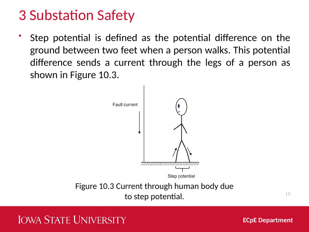
3 Substation Safety Step potential is defined as the potential difference on the ground between two feet when a person walks. This potential difference sends a current through the legs of a person as shown in Figure 10.3. 15 ECpE Department Figure 10.3 Current through human body due to step potential.<br>
16
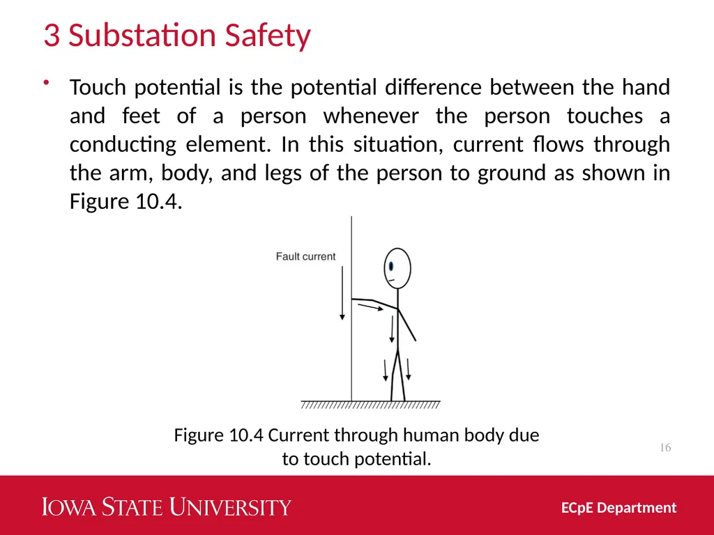
3 Substation Safety Touch potential is the potential difference between the hand and feet of a person whenever the person touches a conducting element. In this situation, current flows through the arm, body, and legs of the person to ground as shown in Figure 10.4. 16 ECpE Department Figure 10.4 Current through human body due to touch potential.<br>
17
3 Substation Safety Multiground neutral substantially helps in reducing both the step and touch potential by distributing the flow of current from ground to neutral. Also, low impedance path for current to flow back to the substation allows the protective devices to react quickly to faults to isolate them. A good ground mat in the substation with several grounding electrodes tied together reduces these potentials and increases safety for operating personnel. 17 ECpE Department<br>
18
4 National Electric Safety Code (NESC) NESC is designed for primary part of the distribution system and has been adopted by law by most states and Public Service Commissions across the United States. It is the authoritative source on good electrical engineering practice for over 90 years.
The NESC is the single most important document for safeguarding of persons from hazards arising from the installation, operation, or maintenance of conductors and equipment in electric supply stations and overhead and underground electric supply and communication lines. 18 ECpE Department<br>
The NESC is the single most important document for safeguarding of persons from hazards arising from the installation, operation, or maintenance of conductors and equipment in electric supply stations and overhead and underground electric supply and communication lines. 18 ECpE Department<br>
19
4 National Electric Safety Code (NESC) Further, it contains extensive updates and critical revisions that directly impact the power utility industry. It also includes work rules for construction, maintenance, and operation of electric supply and communication lines and equipment.
The standard is applicable to the systems and equipment operated by utilities, or similar systems and equipment, of an industrial establishment or complex under the control of qualified persons.
While NESC governs the rules for the system under a utility's authority, safety issues related to customer's premises are governed by the National Electric Code (NEC). 19 ECpE Department<br>
The standard is applicable to the systems and equipment operated by utilities, or similar systems and equipment, of an industrial establishment or complex under the control of qualified persons.
While NESC governs the rules for the system under a utility's authority, safety issues related to customer's premises are governed by the National Electric Code (NEC). 19 ECpE Department<br>
20
5 National Electric Code (NEC) NEC, which has been adopted in all the 50 states of the United States, addresses safety consideration for the secondary part of the distribution systems beyond the distribution transformer.
It is a benchmark for safe electrical design, installation, and inspection to protect people and property from electrical hazards. According to NEC, all grounding systems must be carefully coordinated. 20 ECpE Department<br>
It is a benchmark for safe electrical design, installation, and inspection to protect people and property from electrical hazards. According to NEC, all grounding systems must be carefully coordinated. 20 ECpE Department<br>
21
5 National Electric Code (NEC) It provides guidance on grounding electrode systems, lightning protection, and communications grounding and serves as a reference guide for computer room signal.
Grounding for communications systems must follow the requirements in EIA/TIA Standard 607: Commercial Building Grounding (Earthing) and Bonding Requirements for Telecommunications (and related bulletins). 21 ECpE Department<br>
Grounding for communications systems must follow the requirements in EIA/TIA Standard 607: Commercial Building Grounding (Earthing) and Bonding Requirements for Telecommunications (and related bulletins). 21 ECpE Department<br>
22
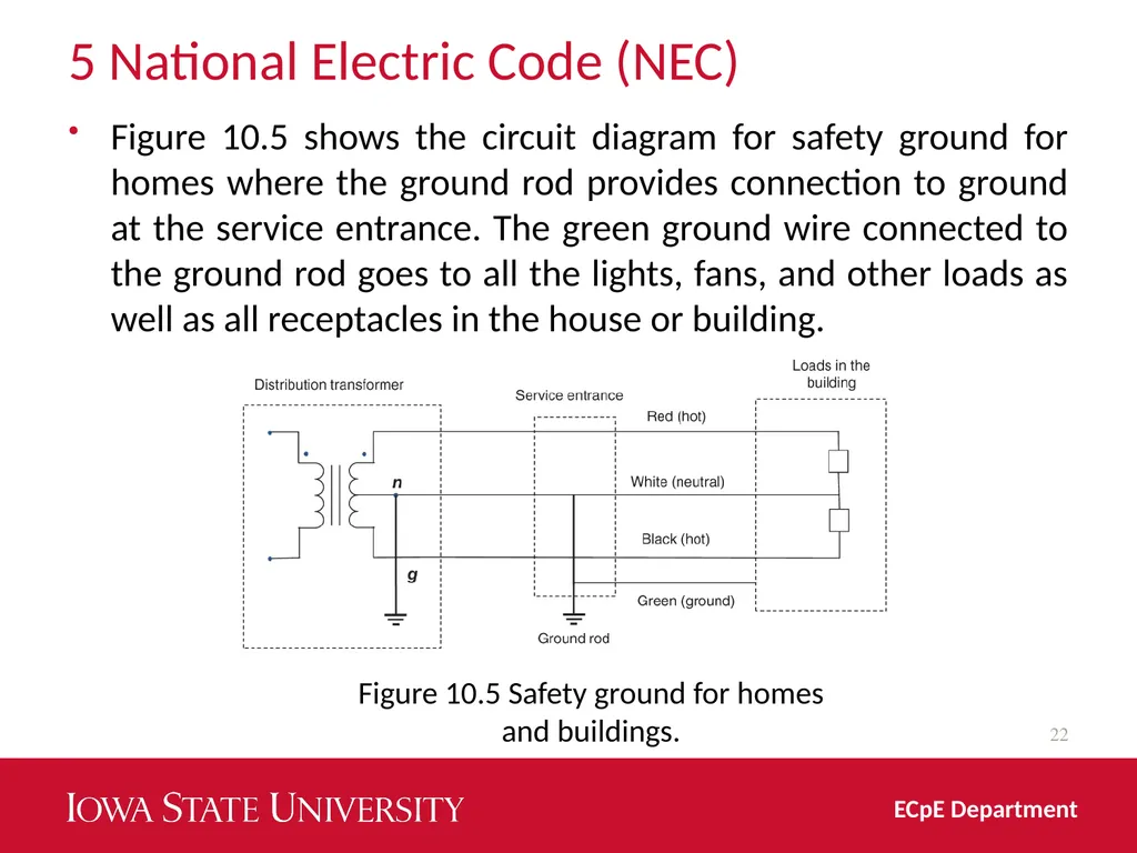
5 National Electric Code (NEC) Figure 10.5 shows the circuit diagram for safety ground for homes where the ground rod provides connection to ground at the service entrance. The green ground wire connected to the ground rod goes to all the lights, fans, and other loads as well as all receptacles in the house or building. 22 ECpE Department Figure 10.5 Safety ground for homes and buildings.<br>
23
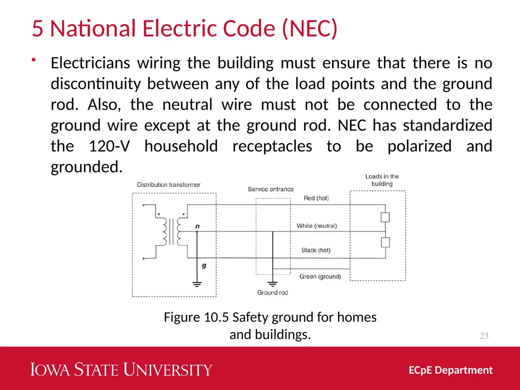
5 National Electric Code (NEC) Electricians wiring the building must ensure that there is no discontinuity between any of the load points and the ground rod. Also, the neutral wire must not be connected to the ground wire except at the ground rod. NEC has standardized the 120‐V household receptacles to be polarized and grounded. 23 ECpE Department Figure 10.5 Safety ground for homes and buildings.<br>
24
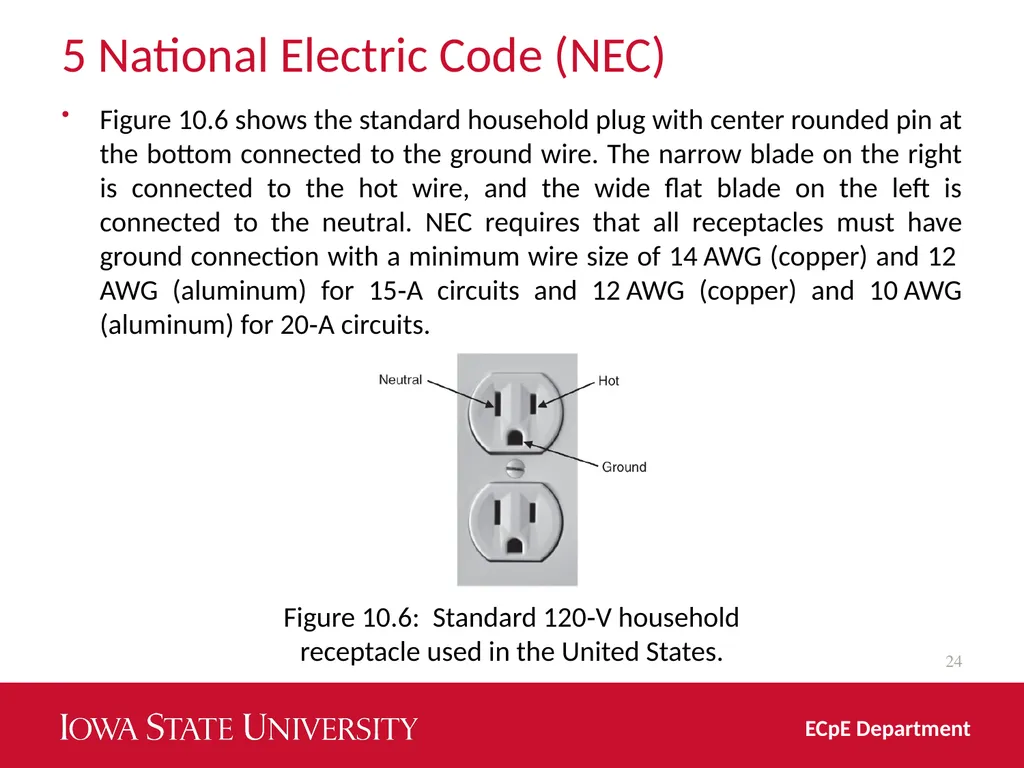
5 National Electric Code (NEC) Figure 10.6 shows the standard household plug with center rounded pin at the bottom connected to the ground wire. The narrow blade on the right is connected to the hot wire, and the wide flat blade on the left is connected to the neutral. NEC requires that all receptacles must have ground connection with a minimum wire size of 14 AWG (copper) and 12 AWG (aluminum) for 15‐A circuits and 12 AWG (copper) and 10 AWG (aluminum) for 20‐A circuits. 24 ECpE Department Figure 10.6: Standard 120‐V household receptacle used in the United States.<br>
25
5 National Electric Code (NEC) Improper grounding in secondary systems can cause safety issues including fire and failure of equipment in homes. Most common problems are open secondary neutral, load incorrectly connected to the ground wire instead of neutral, and connection of the ground wire to neutral at wrong locations.
Open neutral of secondary systems causes the unbalanced current in the two circuits in a house to flow to the ground. If the two circuits have large difference in their loads, the neutral to earth potential can become high due to large current flowing through the ground electrode, which can have high resistance.
Switching on and off loads can cause fluctuations of the neutral‐to‐earth voltage, which in turn causes flicker. Reversal of safety ground and neutral and improper connection of safety ground and neutral create conditions that increase shock hazards. 25 ECpE Department<br>
Open neutral of secondary systems causes the unbalanced current in the two circuits in a house to flow to the ground. If the two circuits have large difference in their loads, the neutral to earth potential can become high due to large current flowing through the ground electrode, which can have high resistance.
Switching on and off loads can cause fluctuations of the neutral‐to‐earth voltage, which in turn causes flicker. Reversal of safety ground and neutral and improper connection of safety ground and neutral create conditions that increase shock hazards. 25 ECpE Department<br>
26
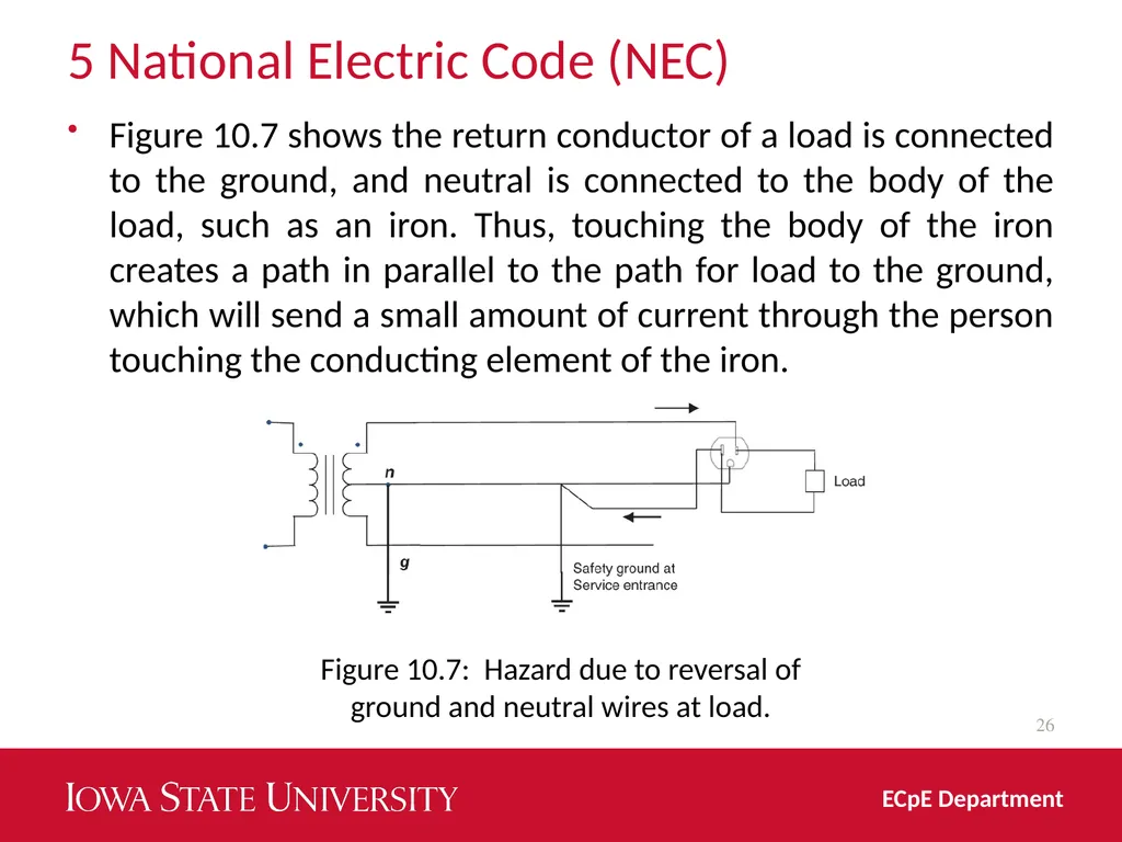
5 National Electric Code (NEC) Figure 10.7 shows the return conductor of a load is connected to the ground, and neutral is connected to the body of the load, such as an iron. Thus, touching the body of the iron creates a path in parallel to the path for load to the ground, which will send a small amount of current through the person touching the conducting element of the iron. 26 ECpE Department Figure 10.7: Hazard due to reversal of ground and neutral wires at load.<br>
27
27 ECpE Department Thank You!<br>