
Introduction to process metallurgy-Unit 2 Prof.


Description: Introduction to process metallurgy-Unit 2 Prof. Monil Salot HYDROMETALLURGY Unit-2 Hydrometallurgical Processes Basics of Hydrometallurgical processes Fundamentals of Unit processes and Unit operations, Principles and types of Leaching
Related Topics
Download Presentation
"Introduction to process metallurgy-Unit 2 Prof." is the property of its rightful owner. Permission is granted to download and print the materials on this website for personal, non-commercial use only, and to display it on your personal computer provided you do not modify the materials and that you retain all copyright notices contained in the materials. By downloading content from our website, you accept the terms of this agreement.
Presentation Transcript
slide1. Introduction to process metallurgy-Unit 2 Prof. Monil Salot<br>
slide2. HYDROMETALLURGY<br>
slide3. Unit-2 Hydrometallurgical Processes
Basics of Hydrometallurgical processes
Fundamentals of Unit processes and Unit operations,
Principles and types of Leaching
Kinetics of leaching
Refining of leached solution
Solvent extraction and ion-exchange processes
Cementation
Gaseous reduction of metals.<br>
slide4. Definition Hydrometallurgy processes are used for low grade ore, for matte alloys and for some other material like concentrate.
It deals with production of metal or pure metal compound with the help of reaction in aqueous solution & organic solution.
It is a process of beneficiation as well as extraction.
It is followed for low grade ores not suitable for pyrometallurgical operations.<br>
slide6. Steps in Hydrometallurgy Preparation of ore for leaching
Grinding, concentration or removal of impurities, roasting, conditioning (chemical treatment) for effective leaching
Leaching
Metallic values in an ore are selectively dissolved by liquid reagent
Rate of leaching – temperature, pressure, pulp density, size of particle, concentration of reagent, aeration, time
Separation of Leach Liquor
Separated from residue after processes such as leaching, settling, thickening, filtration & washing<br>
slide7. Steps in Hydrometallurgy Recovery of Metallic Values from leach liquor
By employing precipitation, cementation, electrolysis, ion exchange, solvent extraction
Recycling of Leach Liquor
After its purification / composition adjustment, it is recycled<br>
slide8. Objectives To produce pure compound which cannot be processed by pyrometallurgy to get metal
To produce metal from crude metal or metal compound
To produce melt directly from ore<br>
slide9. Advantages It gives high extraction of valuable metals.
It is mainly used as method of beneficiation and it will always give byproduct.
Equipments used are relatively simple compare to pyrometallurgy e.g. tank, stirrer, pump, tubes.
Main expenses in cost of reagents. In some process solvent can be regenerated by precipitation techniques & can be reuse.
It is mainly efficient process for low grade & rare metal ore.
It gives very less environmental pollution as to pyrometallurgy.<br>
slide10. Disadvantages Can’t used for many material which may not response to the treatment by leaching method so new solvent & new technique have to be developed.
Large aqueous volumes required
Large space & handling of chemicals required
Corrosion of equipments & disposal of effluent<br>
slide11. Leaching It is a selective dissolution of desired elements of the ore in an appropriate solvent known as leachant or leaching reagent.
Before ore brought in contact with a reacting solution, the ore has to be first crushed and ground to suitable fineness.
This increases the surface area of particles and, therefore, the reaction rate.
In some cases, some preliminary chemical treatments may be necessary. For example, some sulphide ore are made soluble through oxidizing or chloridizing roasting.<br>
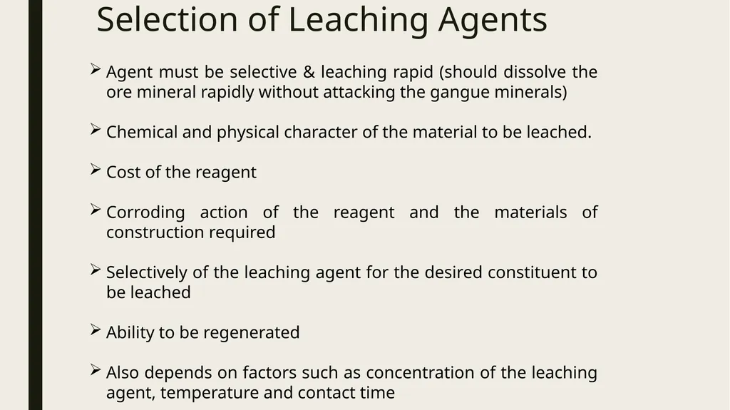
slide12. Selection of Leaching Agents Agent must be selective & leaching rapid (should dissolve the ore mineral rapidly without attacking the gangue minerals)
Chemical and physical character of the material to be leached.
Cost of the reagent
Corroding action of the reagent and the materials of construction required
Selectively of the leaching agent for the desired constituent to be leached
Ability to be regenerated
Also depends on factors such as concentration of the leaching agent, temperature and contact time<br>
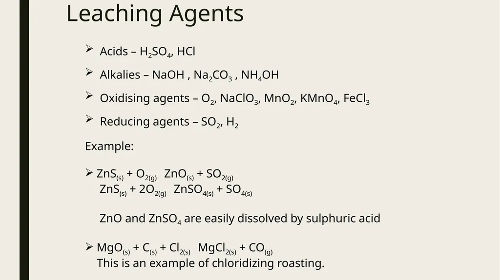
slide13. Leaching Agents Acids – H2SO4, HCl
Alkalies – NaOH , Na2CO3 , NH4OH
Oxidising agents – O2, NaClO3, MnO2, KMnO4, FeCl3
Reducing agents – SO2, H2 Example:
ZnS(s) + O2(g) ZnO(s) + SO2(g)
ZnS(s) + 2O2(g) ZnSO4(s) + SO4(s)
ZnO and ZnSO4 are easily dissolved by sulphuric acid
MgO(s) + C(s) + Cl2(s) MgCl2(s) + CO(g)
This is an example of chloridizing roasting.<br>
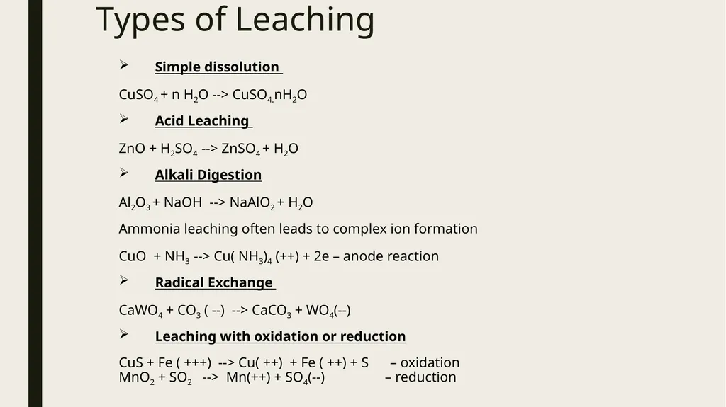
slide14. Types of Leaching Simple dissolution
CuSO4 + n H2O --> CuSO4.nH2O
Acid Leaching
ZnO + H2SO4 --> ZnSO4 + H2O
Alkali Digestion
Al2O3 + NaOH --> NaAlO2 + H2O
Ammonia leaching often leads to complex ion formation
CuO + NH3 --> Cu( NH3)4 (++) + 2e – anode reaction
Radical Exchange
CaWO4 + CO3 ( --) --> CaCO3 + WO4(--)
Leaching with oxidation or reduction
CuS + Fe ( +++) --> Cu( ++) + Fe ( ++) + S – oxidation
MnO2 + SO2 --> Mn(++) + SO4(--) – reduction<br>
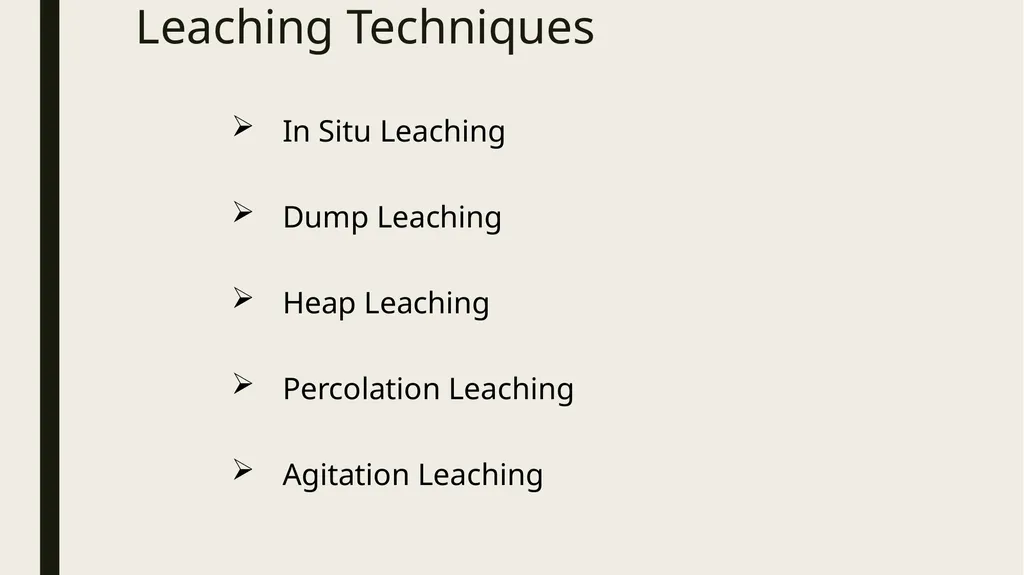
slide15. Leaching Techniques In Situ Leaching
Dump Leaching
Heap Leaching
Percolation Leaching
Agitation Leaching<br>
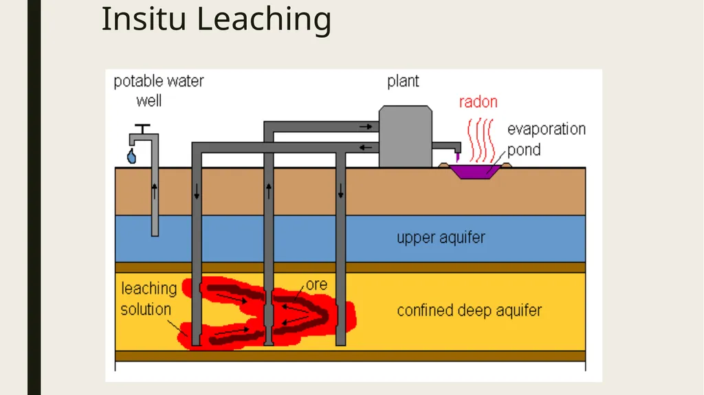
slide16. Insitu Leaching In situ leaching or in situ recovery refers to the mining technique of injecting water underground to dissolve ore and bringing the impregnated water to the surface for extraction.
It uses water circulation through actual are bodies in minerals then leached solution is collected by pumping it out.
E.g. for Cu ore mine water is circulated through oxidized zone.<br>
slide17. Insitu Leaching<br>
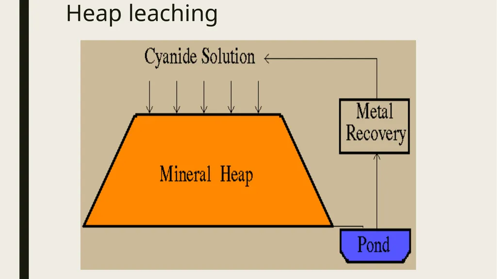
slide18. Heap leaching In this kind of leaching ore is placed above ground level in large heaps which are left exposed to atmospheric moisture, natural rain or water sprays.
The solution formed percolates through the ore.
Higher grades of ore are leached in predetermined manner using dumps.
Examples: Cu, Ni, U ores<br>
slide19. Heap leaching<br>
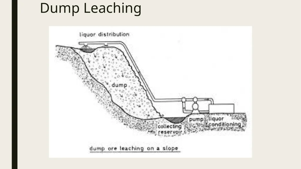
slide20. Dump Leaching Leaching of dumps consisting of off grade ore rejected during mining
Industrial process to extract precious metals and copper from ores.
Similar to heap leaching, however ore is taken directly from the mine and stacked on the leach pad without crushing.
In the case of gold and silver, the dump is irrigated with a dilute cyanide solution that percolates through the ore to dissolve gold and silver.
The solution containing gold and silver exits the base of the dump, is collected and precious metals extracted.
The resultant barren solution is recharged with additional cyanide and returned to the dump.
This method of leaching is usually suitable for low grade ores because it is very low cost.
It operates with slow kinetics and may take up about 1 to 2 years to extract 50% of the desired mineral.<br>
slide21. Dump Leaching<br>
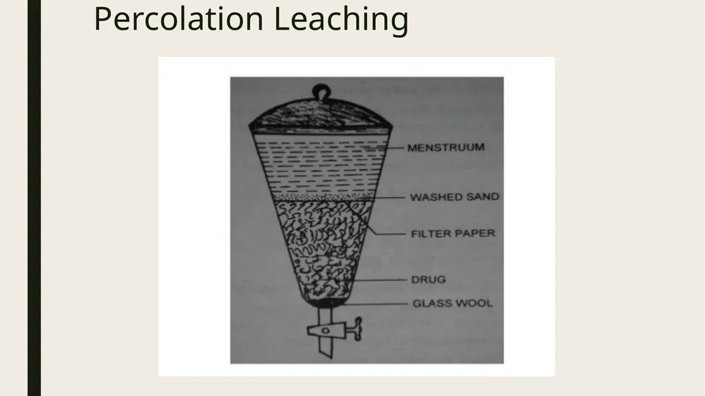
slide22. Percolation Leaching The solvent is percolated through comparatively coarse ore (which is crushed and stored into tanks ) by pumping & pressing it up down several times.
Mixture of coarse & fine ore used for better permeability
By subjecting the ore to 10 or more leach cycles, 80 to 90 percent of metal values can be removed.
Percolation leaching has certain advantages because it is operated in batches.
For example, since each batch is separate or distinct, operational flexibility is greater, and accidental break downs are not that serious.
A percolation leaching is circuit is more versatile and can be employed in the case of ores for which the leaching rate is very slow.<br>
slide23. Percolation Leaching<br>
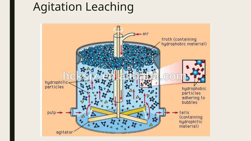
slide24. Agitation Leaching Stirring is used for dissolution process – high pressure, single & multistage stage, counter current modes
In agitation leaching, stirring is used to aid the dissolution process.
There could be variations; for example, atmospheric or high-pressure operation, continuous concurrent or continuous counter current modes, and single-stage or multistage leaching.<br>
slide25. Agitation Leaching<br>
slide26. Special Leaching Techniques Pressure Leaching
Bacterial Leaching<br>
slide27. Pressure Leaching It is used to increase the rate of leaching.
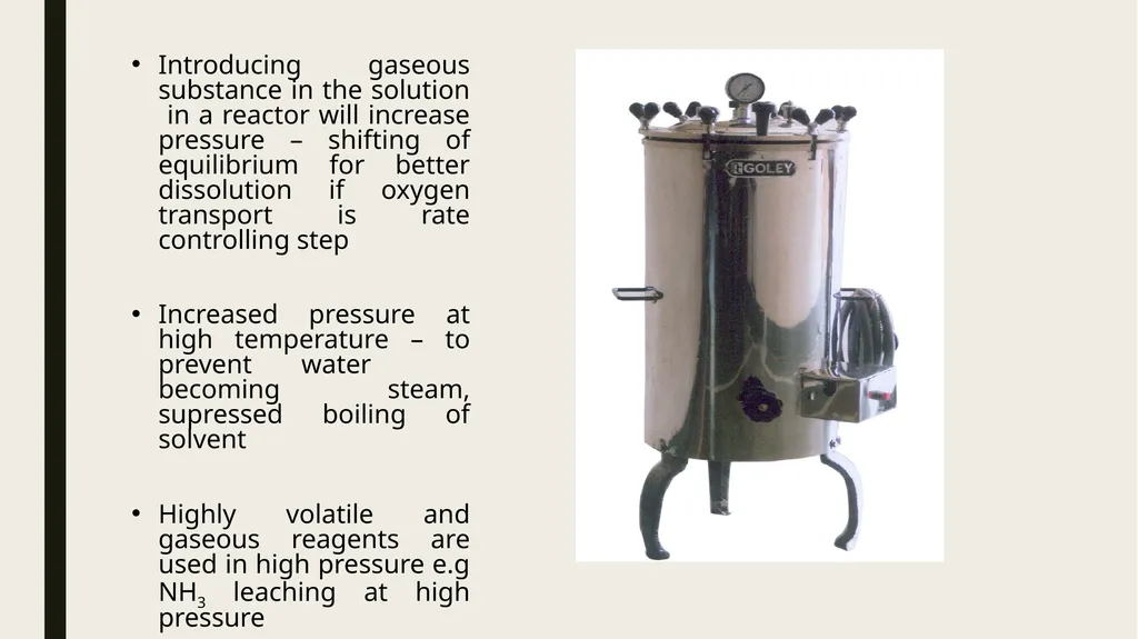
Pressure leaching is carried out in ‘AUTOCLAVE’ at high pressure & temperature.
It is one kind of vessel in which pressure leaching is done.
It is a container made up of water increases and temperature higher than 100˚C become available.
If gaseous reagent like O2 or NH3 are present then concentration of these gases in solution increases during pressure leaching & it will increase rate of leaching.<br>
slide28. Introducing gaseous substance in the solution in a reactor will increase pressure – shifting of equilibrium for better dissolution if oxygen transport is rate controlling step
Increased pressure at high temperature – to prevent water becoming steam, supressed boiling of solvent
Highly volatile and gaseous reagents are used in high pressure e.g NH3 leaching at high pressure<br>
slide29. Pressure Leaching of Oxides
Oxides of metals – Al ,V, Ti & U
In case of U3O8 ore , dissolution by alkali slow – O2 purged at pressure for effective ammoniacal leaching
Pressure Leaching of Sulphide Ores
ZnS, PbS, MoS2, FeS2, CuFeS2, NiS.FeS, CuS are oxidised at high pressure and at elevated temperature in aqueous solutions of H2SO4 , NaOH , NH3
In mixed sulphide ores ( Pentlandite NiS.FeS with CuFeS2) , NiS.FeS is leached in preference to CuFeS2 due to difference in rate of dissolution
Low grade complex Zn & Pb sulphide concentrates is pressure leached in H2SO4 – ZnSO4 as solution & residue as PbSO4 , S & pyrite<br>
slide30. As from Speiss by Pressure Leaching
Fe(As)4 ( Pb Blast furnace) is leached by NaOH to recover As as arsenide
Nickel Matte Pressure Leaching
Leaching of matte ( Ni 70% , Cu, As & Fe) under O2 partial pressure & pH=5 medium – Ni, Cu & As in solution
Zinc Extraction by Pressure Leaching
ZnS occurring with CuFeS2 & pyrite – leaching by H2SO4 , O2 at 6 atm and temperature 110 o C – Zn recovery 98%<br>
slide31. Bacterial Leaching It is leaching done in presence of some type of bacteria (i.e. living organism).
Several types of bacterial can accelerate some leaching reaction selectively to increase both rate of dissolution as well as recovery of metallic values.
These bacteria (e.g. ferrobacillus ferrooxidens, thiobacillus ferrooxidens etc.) are capable of growing on pure inorganic media obtaining their energy requirements by oxidizing inorganic substance like sulphur and thiosulphate to sulphate and ferrous iron to ferric ion.
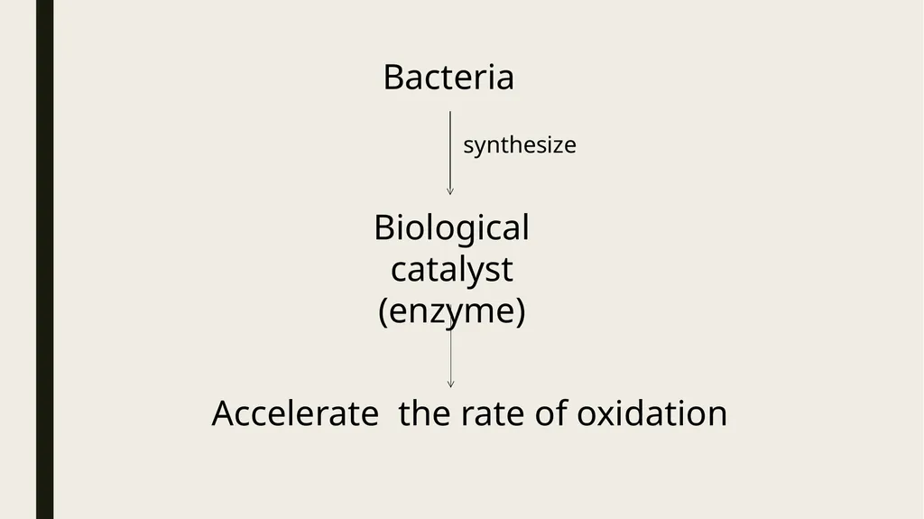
A biological catalyst, called enzyme, is synthesized by bacteria and helps in accelerating the rate of oxidation reaction.<br>
slide32. Bacteria synthesize Biological catalyst
(enzyme) Accelerate the rate of oxidation<br>
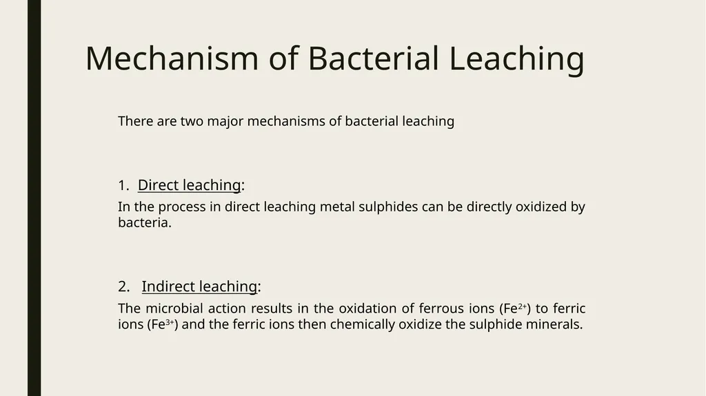
slide33. Mechanism of Bacterial Leaching There are two major mechanisms of bacterial leaching
Direct leaching:
In the process in direct leaching metal sulphides can be directly oxidized by bacteria.
2. Indirect leaching:
The microbial action results in the oxidation of ferrous ions (Fe2+) to ferric ions (Fe3+) and the ferric ions then chemically oxidize the sulphide minerals.<br>
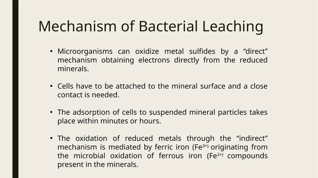
slide34. Mechanism of Bacterial Leaching Microorganisms can oxidize metal sulfides by a “direct” mechanism obtaining electrons directly from the reduced minerals.
Cells have to be attached to the mineral surface and a close contact is needed.
The adsorption of cells to suspended mineral particles takes place within minutes or hours.
The oxidation of reduced metals through the “indirect” mechanism is mediated by ferric iron (Fe3+) originating from the microbial oxidation of ferrous iron (Fe2+) compounds present in the minerals.<br>
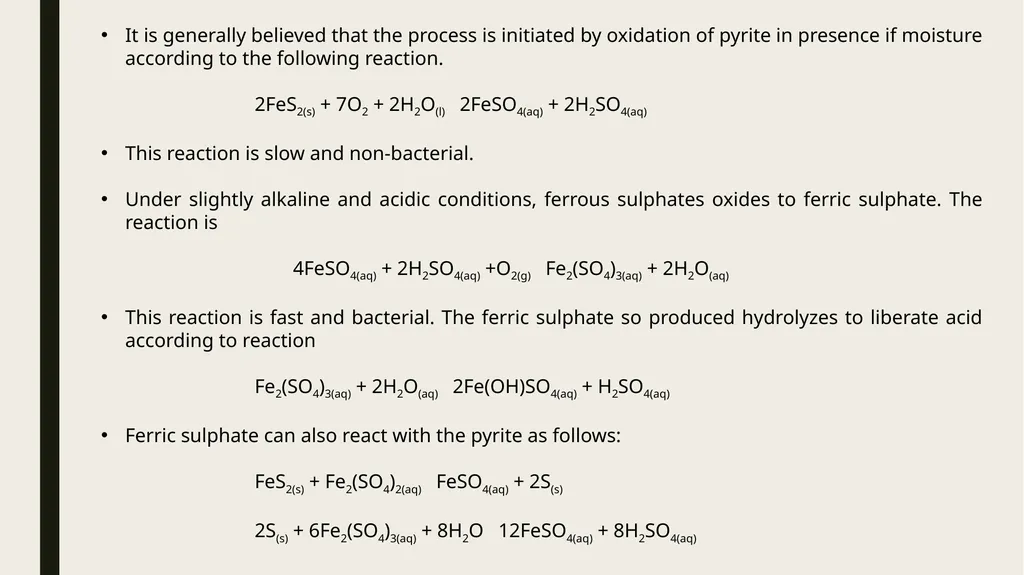
slide35. It is generally believed that the process is initiated by oxidation of pyrite in presence if moisture according to the following reaction.
2FeS2(s) + 7O2 + 2H2O(l) 2FeSO4(aq) + 2H2SO4(aq)
This reaction is slow and non-bacterial.
Under slightly alkaline and acidic conditions, ferrous sulphates oxides to ferric sulphate. The reaction is
4FeSO4(aq) + 2H2SO4(aq) +O2(g) Fe2(SO4)3(aq) + 2H2O(aq)
This reaction is fast and bacterial. The ferric sulphate so produced hydrolyzes to liberate acid according to reaction
Fe2(SO4)3(aq) + 2H2O(aq) 2Fe(OH)SO4(aq) + H2SO4(aq)
Ferric sulphate can also react with the pyrite as follows:
FeS2(s) + Fe2(SO4)2(aq) FeSO4(aq) + 2S(s)
2S(s) + 6Fe2(SO4)3(aq) + 8H2O 12FeSO4(aq) + 8H2SO4(aq)<br>
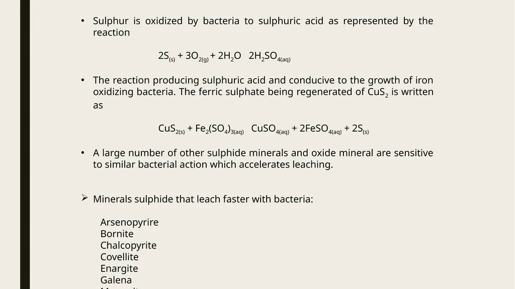
slide36. Sulphur is oxidized by bacteria to sulphuric acid as represented by the reaction
2S(s) + 3O2(g) + 2H2O 2H2SO4(aq)
The reaction producing sulphuric acid and conducive to the growth of iron oxidizing bacteria. The ferric sulphate being regenerated of CuS2 is written as
CuS2(s) + Fe2(SO4)3(aq) CuSO4(aq) + 2FeSO4(aq) + 2S(s)
A large number of other sulphide minerals and oxide mineral are sensitive to similar bacterial action which accelerates leaching.
Minerals sulphide that leach faster with bacteria:
Arsenopyrire
Bornite
Chalcopyrite
Covellite
Enargite
Galena
Marcasite<br>
slide37. Effect of Factors on Bacterial Leaching
Temperature – oxidation of Fe best - 30-35 C , higher than 70 C - destroyed
Addition of Nutrients – FeSO4 , FeS2 , (NH4)2SO4 increase ferrous ion concentration – bacteria become more active
Particle Size & Bed Depth – Shallow depth & fine particle with enough permeability
Radiation – direct sunlight makes bacteria inactive
Acidity & Aeration – Oxidizing bacteria active only in acid ( pH 2-3.5) , oxygen supply to micro-organism vital<br>
slide38. The activity of the bacteria must be sustained by conditions favorable to their survival & population growth.
The conditions include:
Right temperature range (30-45˚C)
Presence of nutrients ( (NH4)2, SO4 etc. ) (bacteria become active)
Correct particle size & bed depth (surface area of particle and permeability of bed)
Absence of direct sunlight (bacteria inactive to due direct sunlight)
Correct pH range (2-3.5) (alkaline medium not suitable)
Humid atmosphere
Good aeration through bubbling
Agitation can increase the process<br>
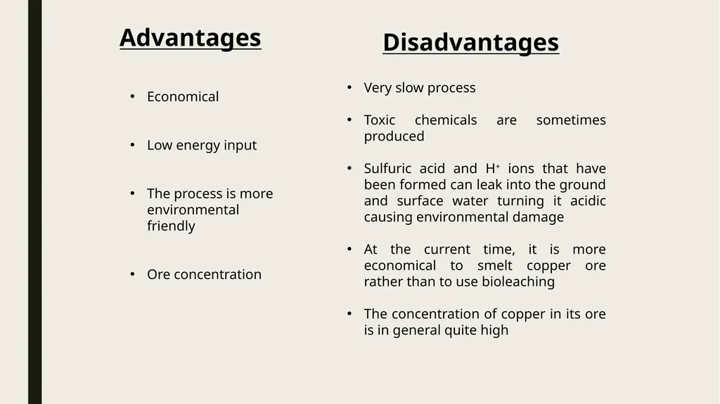
slide39. Disadvantages Advantages Economical
Low energy input
The process is more environmental friendly
Ore concentration Very slow process
Toxic chemicals are sometimes produced
Sulfuric acid and H+ ions that have been formed can leak into the ground and surface water turning it acidic causing environmental damage
At the current time, it is more economical to smelt copper ore rather than to use bioleaching
The concentration of copper in its ore is in general quite high<br>
slide40. Kinetics of Leaching Factors affecting rate of leaching are :
Diffusion of reagent from bulk of solution to solid surface of mineral
Diffusion of reagent to soild porous reaction layer of partially leached product
Reaction of reagent with mineral surface to form soluble metal ion
Movement of product metal species through porous product layer
Rate controlling steps like diffusion or reaction will be affected by size of material, agitation / stirring, temperature , concentration of reactants & products<br>
slide41. Purification of Leach Liquor To remove undesirable soluble impurities compound of gangue metal
To get leach solution that contains only desire metal compound
Common methods
Precipitation
Ion-exchange
Solvent exchange<br>
slide42. Precipitation Precipitation is the formation of a solid in a solution or inside another solid during a chemical reaction or by diffusion in a solid.
The impurities in the leach liquor can be eliminated by precipitation under controlled condition of:
pH
concentration
special additives
Traditional principles of analytical chemistry are made use of in such reactions.<br>
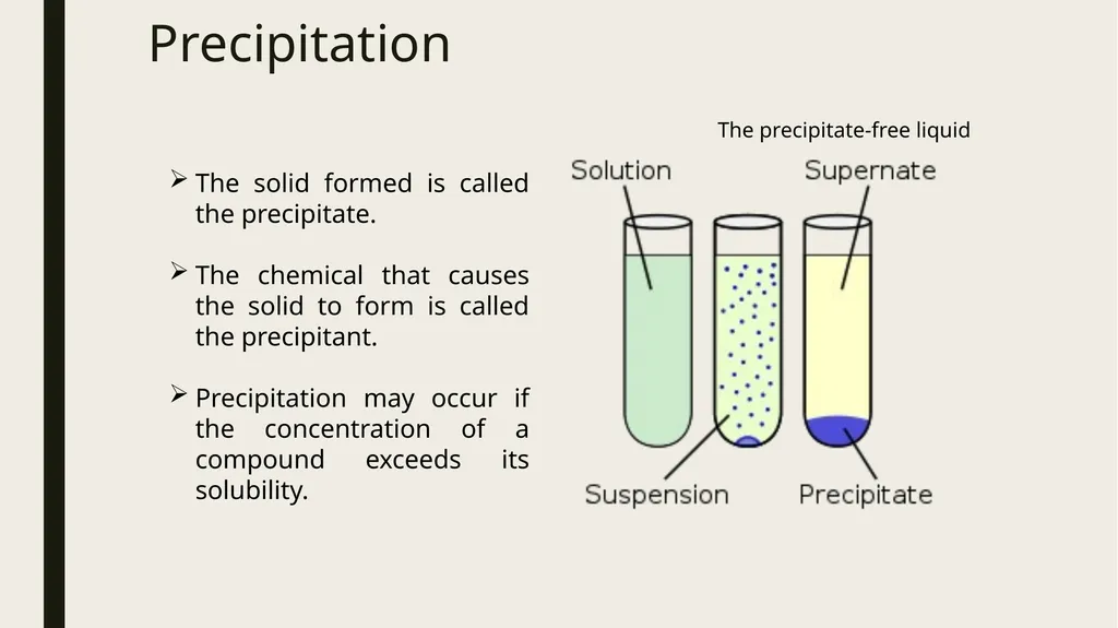
slide43. Precipitation The solid formed is called the precipitate.
The chemical that causes the solid to form is called the precipitant.
Precipitation may occur if the concentration of a compound exceeds its solubility. The precipitate-free liquid<br>
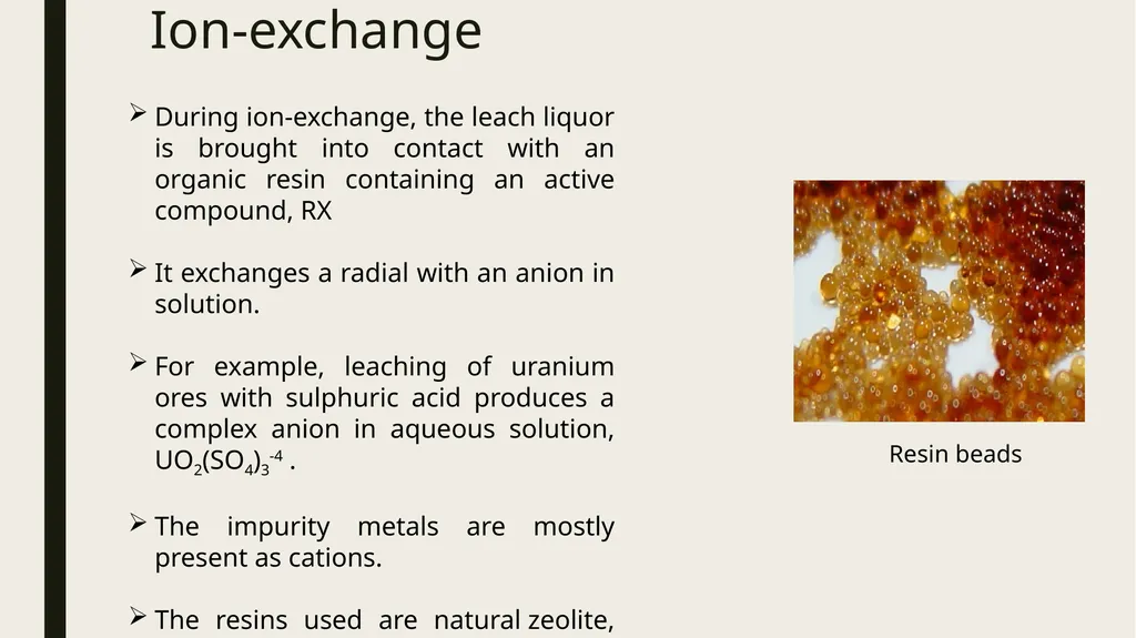
slide44. Ion-exchange During ion-exchange, the leach liquor is brought into contact with an organic resin containing an active compound, RX
It exchanges a radial with an anion in solution.
For example, leaching of uranium ores with sulphuric acid produces a complex anion in aqueous solution, UO2(SO4)3-4 .
The impurity metals are mostly present as cations.
The resins used are natural zeolite, activated carbon and liquid organics. Resin beads<br>
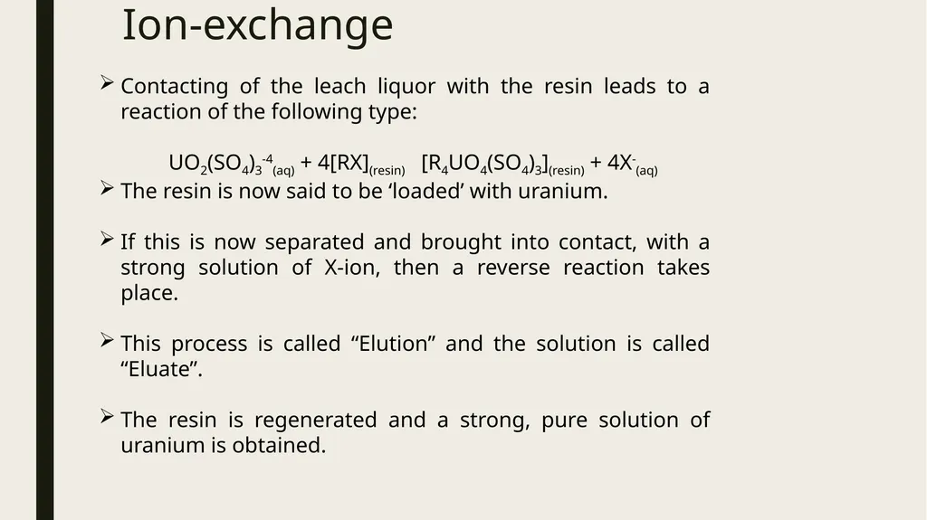
slide45. Ion-exchange Contacting of the leach liquor with the resin leads to a reaction of the following type:
UO2(SO4)3-4(aq) + 4[RX](resin) [R4UO4(SO4)3](resin) + 4X-(aq)
The resin is now said to be ‘loaded’ with uranium.
If this is now separated and brought into contact, with a strong solution of X-ion, then a reverse reaction takes place.
This process is called “Elution” and the solution is called “Eluate”.
The resin is regenerated and a strong, pure solution of uranium is obtained.<br>
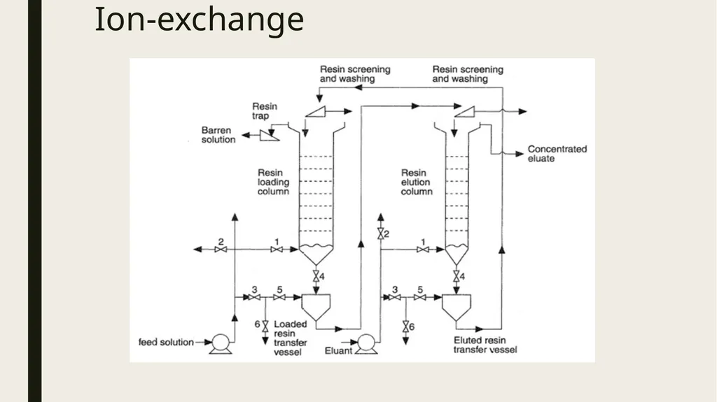
slide46. Ion-exchange<br>
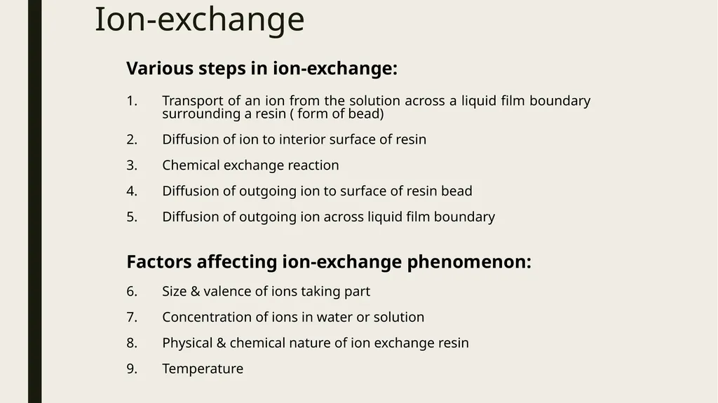
slide47. Ion-exchange Various steps in ion-exchange:
Transport of an ion from the solution across a liquid film boundary surrounding a resin ( form of bead)
Diffusion of ion to interior surface of resin
Chemical exchange reaction
Diffusion of outgoing ion to surface of resin bead
Diffusion of outgoing ion across liquid film boundary
Factors affecting ion-exchange phenomenon:
Size & valence of ions taking part
Concentration of ions in water or solution
Physical & chemical nature of ion exchange resin
Temperature<br>
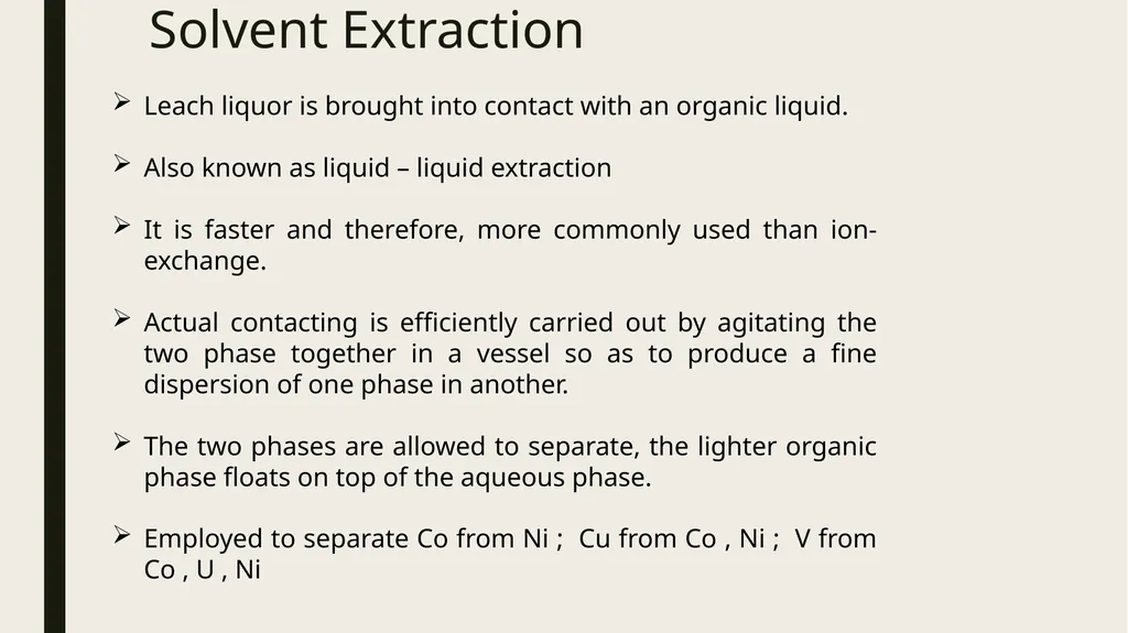
slide48. Solvent Extraction Leach liquor is brought into contact with an organic liquid.
Also known as liquid – liquid extraction
It is faster and therefore, more commonly used than ion-exchange.
Actual contacting is efficiently carried out by agitating the two phase together in a vessel so as to produce a fine dispersion of one phase in another.
The two phases are allowed to separate, the lighter organic phase floats on top of the aqueous phase.
Employed to separate Co from Ni ; Cu from Co , Ni ; V from Co , U , Ni<br>
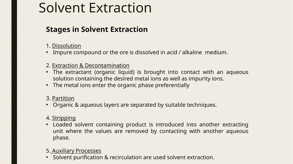
slide49. Solvent Extraction Stages in Solvent Extraction
1. Dissolution
Impure compound or the ore is dissolved in acid / alkaline medium.
2. Extraction & Decontamination
The extractant (organic liquid) is brought into contact with an aqueous solution containing the desired metal ions as well as impurity ions.
The metal ions enter the organic phase preferentially
3. Partition
Organic & aqueous layers are separated by suitable techniques.
4. Stripping
Loaded solvent containing product is introduced into another extracting unit where the values are removed by contacting with another aqueous phase.
5. Auxiliary Processes
Solvent purification & recirculation are used solvent extraction.<br>
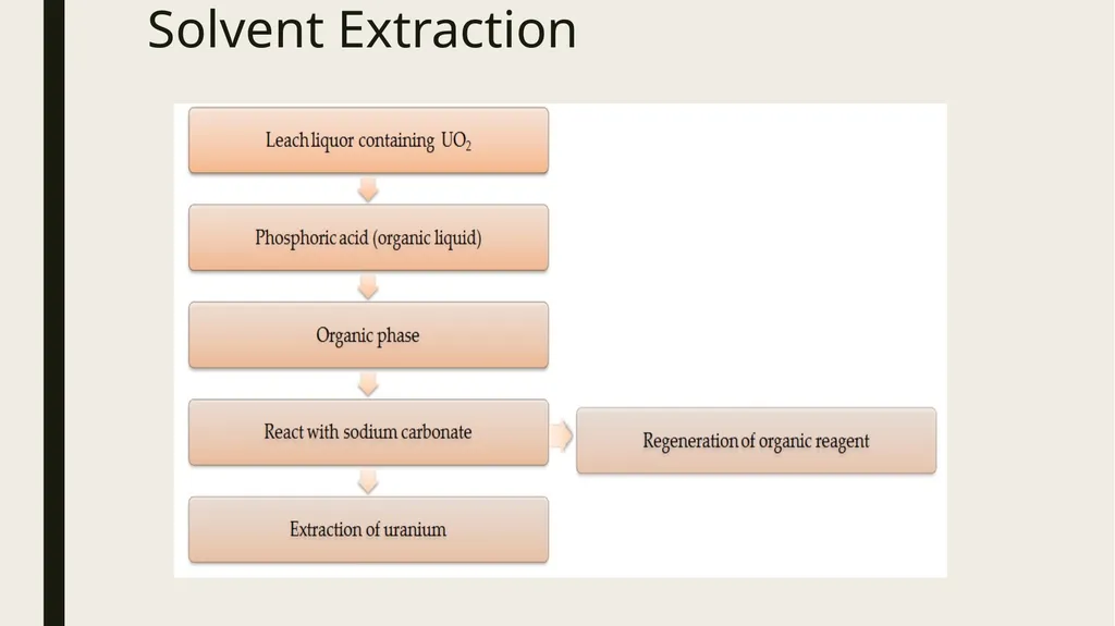
slide50. Solvent Extraction<br>
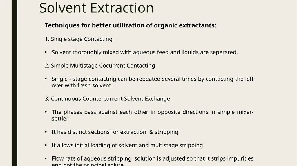
slide51. Solvent Extraction Techniques for better utilization of organic extractants:
1. Single stage Contacting
Solvent thoroughly mixed with aqueous feed and liquids are seperated.
2. Simple Multistage Cocurrent Contacting
Single - stage contacting can be repeated several times by contacting the left over with fresh solvent.
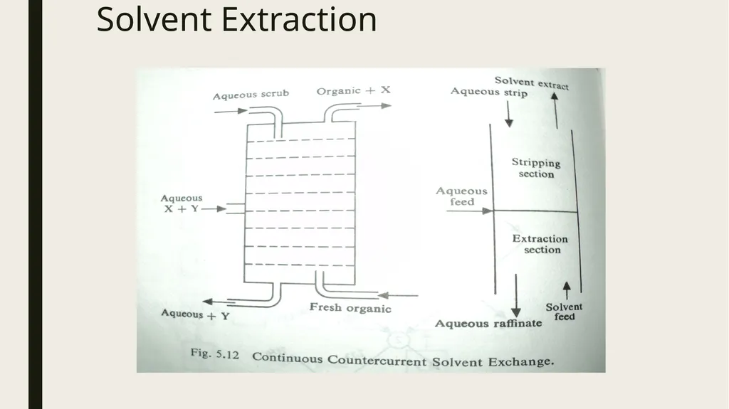
3. Continuous Countercurrent Solvent Exchange
The phases pass against each other in opposite directions in simple mixer-settler
It has distinct sections for extraction & stripping
It allows initial loading of solvent and multistage stripping
Flow rate of aqueous stripping solution is adjusted so that it strips impurities and not the principal solute<br>
slide52. Solvent Extraction<br>
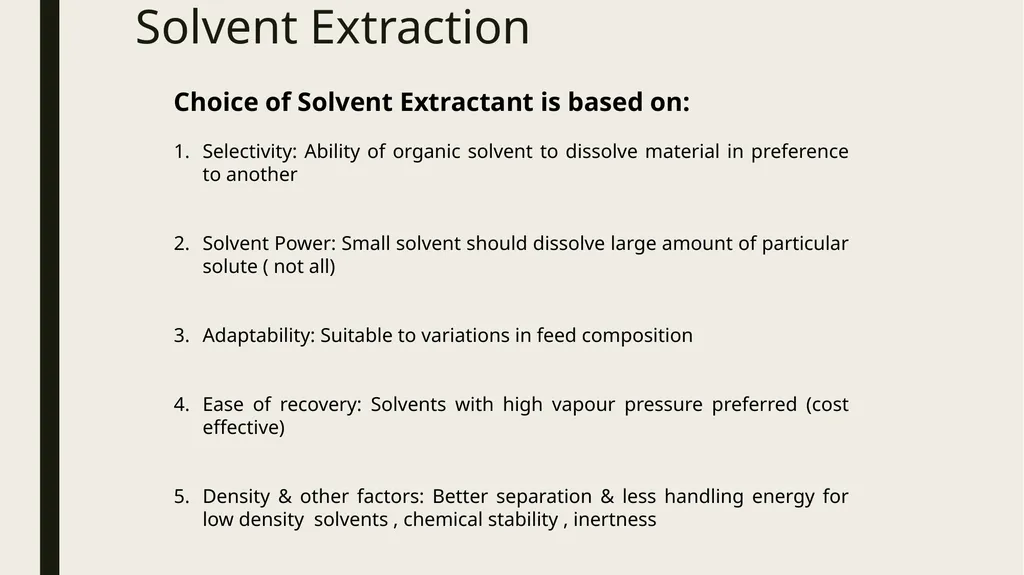
slide53. Solvent Extraction Choice of Solvent Extractant is based on:
Selectivity: Ability of organic solvent to dissolve material in preference to another
Solvent Power: Small solvent should dissolve large amount of particular solute ( not all)
Adaptability: Suitable to variations in feed composition
Ease of recovery: Solvents with high vapour pressure preferred (cost effective)
Density & other factors: Better separation & less handling energy for low density solvents , chemical stability , inertness<br>
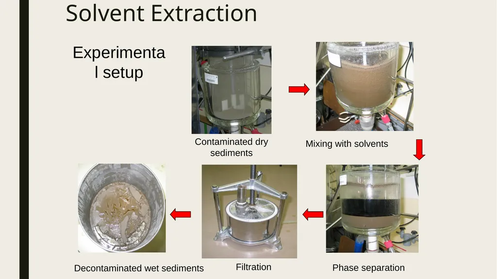
slide54. Solvent Extraction Contaminated dry sediments Mixing with solvents Phase separation Filtration Decontaminated wet sediments Experimental setup<br>
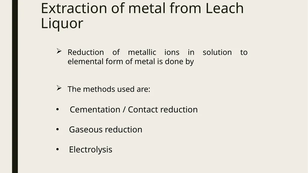
slide55. Extraction of metal from Leach Liquor Reduction of metallic ions in solution to elemental form of metal is done by
The methods used are:
Cementation / Contact reduction
Gaseous reduction
Electrolysis<br>
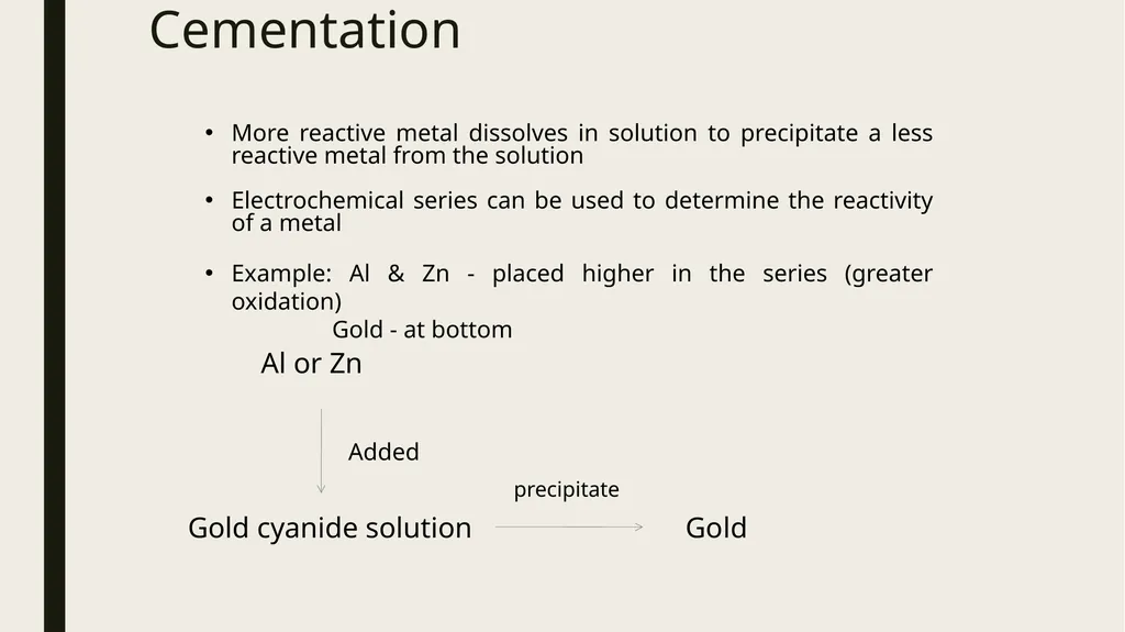
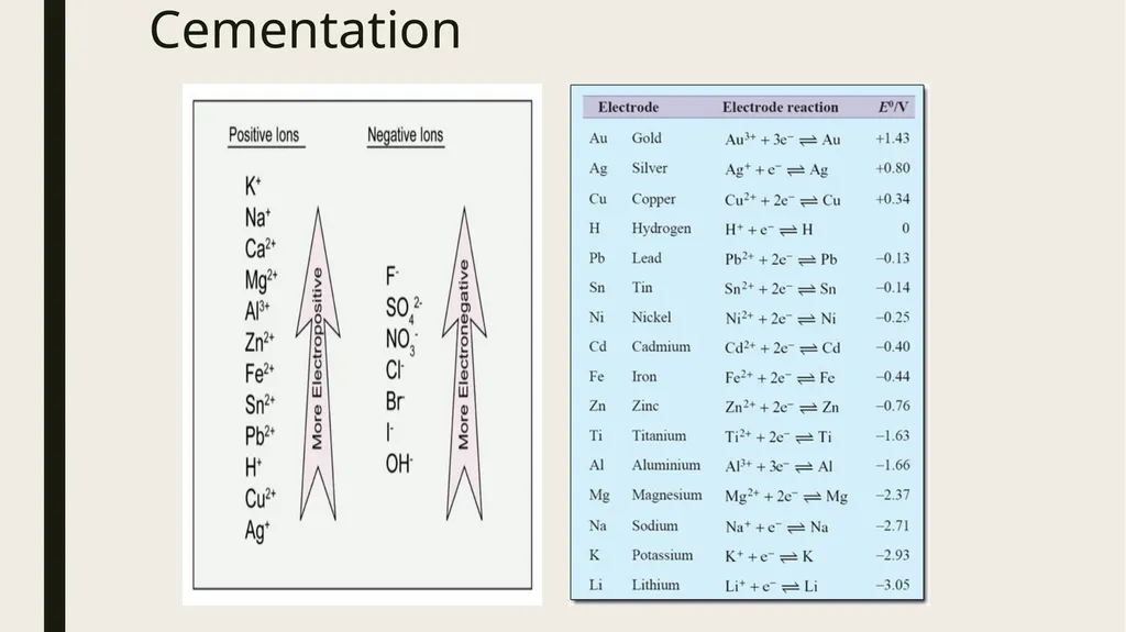
slide56. Cementation More reactive metal dissolves in solution to precipitate a less reactive metal from the solution
Electrochemical series can be used to determine the reactivity of a metal
Example: Al & Zn - placed higher in the series (greater oxidation)
Gold - at bottom Added Gold cyanide solution Al or Zn precipitate Gold<br>
slide57. Cementation<br>
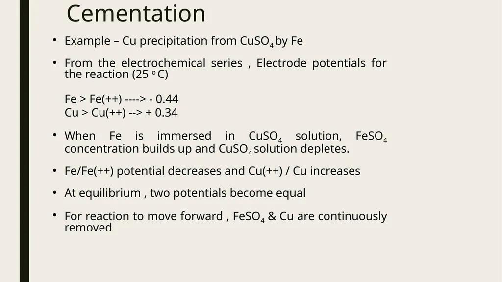
slide58. Cementation Example – Cu precipitation from CuSO4 by Fe
From the electrochemical series , Electrode potentials for the reaction (25 o C)
Fe > Fe(++) ----> - 0.44
Cu > Cu(++) --> + 0.34
When Fe is immersed in CuSO4 solution, FeSO4 concentration builds up and CuSO4 solution depletes.
Fe/Fe(++) potential decreases and Cu(++) / Cu increases
At equilibrium , two potentials become equal
For reaction to move forward , FeSO4 & Cu are continuously removed<br>
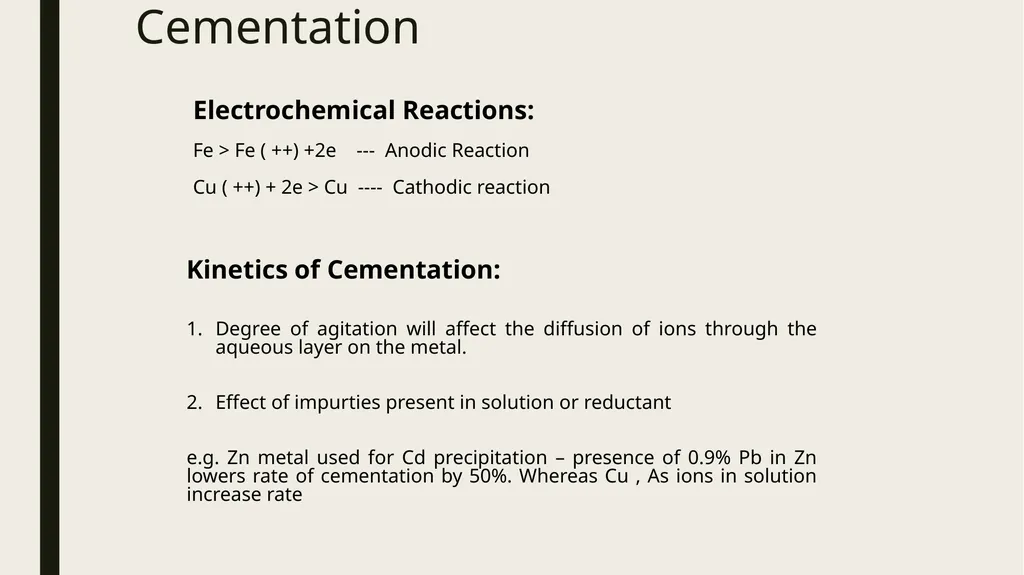
slide59. Cementation Kinetics of Cementation:
Degree of agitation will affect the diffusion of ions through the aqueous layer on the metal.
Effect of impurties present in solution or reductant
e.g. Zn metal used for Cd precipitation – presence of 0.9% Pb in Zn lowers rate of cementation by 50%. Whereas Cu , As ions in solution increase rate Electrochemical Reactions:
Fe > Fe ( ++) +2e --- Anodic Reaction
Cu ( ++) + 2e > Cu ---- Cathodic reaction<br>
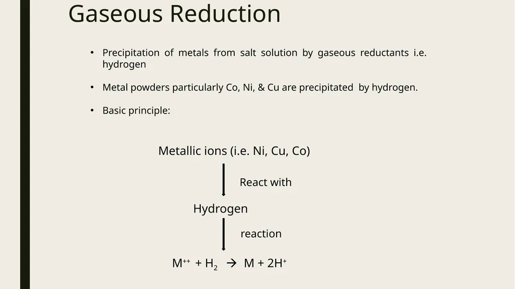
slide60. Gaseous Reduction Precipitation of metals from salt solution by gaseous reductants i.e. hydrogen
Metal powders particularly Co, Ni, & Cu are precipitated by hydrogen.
Basic principle: Metallic ions (i.e. Ni, Cu, Co) React with Hydrogen reaction M++ + H2 M + 2H+<br>
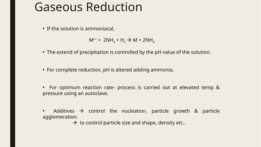
slide61. Gaseous Reduction If the solution is ammoniacal,
The extend of precipitation is controlled by the pH value of the solution.
For complete reduction, pH is altered adding ammonia.
For optimum reaction rate- process is carried out at elevated temp & pressure using an autoclave.
Additives control the nucleation, particle growth & particle agglomeration.
to control particle size and shape, density etc.. M++ + 2NH3 + H2 M + 2NH4<br>
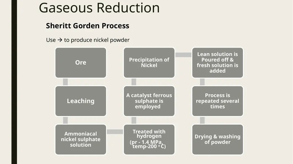
slide62. Gaseous Reduction Sheritt Gorden Process
Use to produce nickel powder<br>
slide63. UNIT OPERATION AND UNIT PROCESSES The process which involves chemical reaction is called unit process like chemical reactions, chemisorptions, nitration,
Whereas the process which involves only physical change is called as unit operation like distillation, physical adsorption etc.<br>
slide64. UNIT OPREATTION A unit operation is a basic step in a process. Unit operations involve bringing a physical change such as separation, crystallization, evaporation, filtration etc.
For example, in milk processing, homogenization, pasteurization, chilling, and packaging are each unit operations which are connected to create the overall process.
A process may have many unit operations to obtain the desired product.<br>
slide65. Unit operations consist of five classes: Fluid flow processes, including fluids transportation, filtration, solids fluidization
Heat transfer processes, including evaporation, condensation
Mass transfer processes, including gas absorption, distillation, extraction, adsorption, drying
Thermodynamic processes, including gas liquefaction, refrigeration
Mechanical processes, including solids transportation, crushing and pulverization, screening and sieving<br>
slide66. Unit operations also fall in the following categories Combination (mixing)
Separation (distillation)
Reaction (chemical reaction)<br>
slide67. UNIT PROCESS A Unit Process is a step in manufacturing in which chemical reaction takes place, e.g., the oxidation of paraxylene to terephthalic acid is a unit process, the hydrogenation of vegetable oil to ghee is a unit process. In 1930 P.H. Groggins introduced Unit processes in order to classify and standardize chemical reactions.
Unit process means that a chemical change occurs (i.e., nitration, helogenation, sulphonation).<br>
slide68. Unit processing consists of the following important processes Oxidation
Reduction
Hydrogenation
Dehydrogenation
Hydrolysis
Hydration
Dehydration
Halogenation
Nitrification
Sulfonation
Ammoniation
Alkaline fusion
Alkylation
Dealkylation
Esterification
Polymerization
Polycondensation
Catalysis<br>
slide2. HYDROMETALLURGY<br>
slide3. Unit-2 Hydrometallurgical Processes
Basics of Hydrometallurgical processes
Fundamentals of Unit processes and Unit operations,
Principles and types of Leaching
Kinetics of leaching
Refining of leached solution
Solvent extraction and ion-exchange processes
Cementation
Gaseous reduction of metals.<br>
slide4. Definition Hydrometallurgy processes are used for low grade ore, for matte alloys and for some other material like concentrate.
It deals with production of metal or pure metal compound with the help of reaction in aqueous solution & organic solution.
It is a process of beneficiation as well as extraction.
It is followed for low grade ores not suitable for pyrometallurgical operations.<br>
slide6. Steps in Hydrometallurgy Preparation of ore for leaching
Grinding, concentration or removal of impurities, roasting, conditioning (chemical treatment) for effective leaching
Leaching
Metallic values in an ore are selectively dissolved by liquid reagent
Rate of leaching – temperature, pressure, pulp density, size of particle, concentration of reagent, aeration, time
Separation of Leach Liquor
Separated from residue after processes such as leaching, settling, thickening, filtration & washing<br>
slide7. Steps in Hydrometallurgy Recovery of Metallic Values from leach liquor
By employing precipitation, cementation, electrolysis, ion exchange, solvent extraction
Recycling of Leach Liquor
After its purification / composition adjustment, it is recycled<br>
slide8. Objectives To produce pure compound which cannot be processed by pyrometallurgy to get metal
To produce metal from crude metal or metal compound
To produce melt directly from ore<br>
slide9. Advantages It gives high extraction of valuable metals.
It is mainly used as method of beneficiation and it will always give byproduct.
Equipments used are relatively simple compare to pyrometallurgy e.g. tank, stirrer, pump, tubes.
Main expenses in cost of reagents. In some process solvent can be regenerated by precipitation techniques & can be reuse.
It is mainly efficient process for low grade & rare metal ore.
It gives very less environmental pollution as to pyrometallurgy.<br>
slide10. Disadvantages Can’t used for many material which may not response to the treatment by leaching method so new solvent & new technique have to be developed.
Large aqueous volumes required
Large space & handling of chemicals required
Corrosion of equipments & disposal of effluent<br>
slide11. Leaching It is a selective dissolution of desired elements of the ore in an appropriate solvent known as leachant or leaching reagent.
Before ore brought in contact with a reacting solution, the ore has to be first crushed and ground to suitable fineness.
This increases the surface area of particles and, therefore, the reaction rate.
In some cases, some preliminary chemical treatments may be necessary. For example, some sulphide ore are made soluble through oxidizing or chloridizing roasting.<br>
slide12. Selection of Leaching Agents Agent must be selective & leaching rapid (should dissolve the ore mineral rapidly without attacking the gangue minerals)
Chemical and physical character of the material to be leached.
Cost of the reagent
Corroding action of the reagent and the materials of construction required
Selectively of the leaching agent for the desired constituent to be leached
Ability to be regenerated
Also depends on factors such as concentration of the leaching agent, temperature and contact time<br>
slide13. Leaching Agents Acids – H2SO4, HCl
Alkalies – NaOH , Na2CO3 , NH4OH
Oxidising agents – O2, NaClO3, MnO2, KMnO4, FeCl3
Reducing agents – SO2, H2 Example:
ZnS(s) + O2(g) ZnO(s) + SO2(g)
ZnS(s) + 2O2(g) ZnSO4(s) + SO4(s)
ZnO and ZnSO4 are easily dissolved by sulphuric acid
MgO(s) + C(s) + Cl2(s) MgCl2(s) + CO(g)
This is an example of chloridizing roasting.<br>
slide14. Types of Leaching Simple dissolution
CuSO4 + n H2O --> CuSO4.nH2O
Acid Leaching
ZnO + H2SO4 --> ZnSO4 + H2O
Alkali Digestion
Al2O3 + NaOH --> NaAlO2 + H2O
Ammonia leaching often leads to complex ion formation
CuO + NH3 --> Cu( NH3)4 (++) + 2e – anode reaction
Radical Exchange
CaWO4 + CO3 ( --) --> CaCO3 + WO4(--)
Leaching with oxidation or reduction
CuS + Fe ( +++) --> Cu( ++) + Fe ( ++) + S – oxidation
MnO2 + SO2 --> Mn(++) + SO4(--) – reduction<br>
slide15. Leaching Techniques In Situ Leaching
Dump Leaching
Heap Leaching
Percolation Leaching
Agitation Leaching<br>
slide16. Insitu Leaching In situ leaching or in situ recovery refers to the mining technique of injecting water underground to dissolve ore and bringing the impregnated water to the surface for extraction.
It uses water circulation through actual are bodies in minerals then leached solution is collected by pumping it out.
E.g. for Cu ore mine water is circulated through oxidized zone.<br>
slide17. Insitu Leaching<br>
slide18. Heap leaching In this kind of leaching ore is placed above ground level in large heaps which are left exposed to atmospheric moisture, natural rain or water sprays.
The solution formed percolates through the ore.
Higher grades of ore are leached in predetermined manner using dumps.
Examples: Cu, Ni, U ores<br>
slide19. Heap leaching<br>
slide20. Dump Leaching Leaching of dumps consisting of off grade ore rejected during mining
Industrial process to extract precious metals and copper from ores.
Similar to heap leaching, however ore is taken directly from the mine and stacked on the leach pad without crushing.
In the case of gold and silver, the dump is irrigated with a dilute cyanide solution that percolates through the ore to dissolve gold and silver.
The solution containing gold and silver exits the base of the dump, is collected and precious metals extracted.
The resultant barren solution is recharged with additional cyanide and returned to the dump.
This method of leaching is usually suitable for low grade ores because it is very low cost.
It operates with slow kinetics and may take up about 1 to 2 years to extract 50% of the desired mineral.<br>
slide21. Dump Leaching<br>
slide22. Percolation Leaching The solvent is percolated through comparatively coarse ore (which is crushed and stored into tanks ) by pumping & pressing it up down several times.
Mixture of coarse & fine ore used for better permeability
By subjecting the ore to 10 or more leach cycles, 80 to 90 percent of metal values can be removed.
Percolation leaching has certain advantages because it is operated in batches.
For example, since each batch is separate or distinct, operational flexibility is greater, and accidental break downs are not that serious.
A percolation leaching is circuit is more versatile and can be employed in the case of ores for which the leaching rate is very slow.<br>
slide23. Percolation Leaching<br>
slide24. Agitation Leaching Stirring is used for dissolution process – high pressure, single & multistage stage, counter current modes
In agitation leaching, stirring is used to aid the dissolution process.
There could be variations; for example, atmospheric or high-pressure operation, continuous concurrent or continuous counter current modes, and single-stage or multistage leaching.<br>
slide25. Agitation Leaching<br>
slide26. Special Leaching Techniques Pressure Leaching
Bacterial Leaching<br>
slide27. Pressure Leaching It is used to increase the rate of leaching.
Pressure leaching is carried out in ‘AUTOCLAVE’ at high pressure & temperature.
It is one kind of vessel in which pressure leaching is done.
It is a container made up of water increases and temperature higher than 100˚C become available.
If gaseous reagent like O2 or NH3 are present then concentration of these gases in solution increases during pressure leaching & it will increase rate of leaching.<br>
slide28. Introducing gaseous substance in the solution in a reactor will increase pressure – shifting of equilibrium for better dissolution if oxygen transport is rate controlling step
Increased pressure at high temperature – to prevent water becoming steam, supressed boiling of solvent
Highly volatile and gaseous reagents are used in high pressure e.g NH3 leaching at high pressure<br>
slide29. Pressure Leaching of Oxides
Oxides of metals – Al ,V, Ti & U
In case of U3O8 ore , dissolution by alkali slow – O2 purged at pressure for effective ammoniacal leaching
Pressure Leaching of Sulphide Ores
ZnS, PbS, MoS2, FeS2, CuFeS2, NiS.FeS, CuS are oxidised at high pressure and at elevated temperature in aqueous solutions of H2SO4 , NaOH , NH3
In mixed sulphide ores ( Pentlandite NiS.FeS with CuFeS2) , NiS.FeS is leached in preference to CuFeS2 due to difference in rate of dissolution
Low grade complex Zn & Pb sulphide concentrates is pressure leached in H2SO4 – ZnSO4 as solution & residue as PbSO4 , S & pyrite<br>
slide30. As from Speiss by Pressure Leaching
Fe(As)4 ( Pb Blast furnace) is leached by NaOH to recover As as arsenide
Nickel Matte Pressure Leaching
Leaching of matte ( Ni 70% , Cu, As & Fe) under O2 partial pressure & pH=5 medium – Ni, Cu & As in solution
Zinc Extraction by Pressure Leaching
ZnS occurring with CuFeS2 & pyrite – leaching by H2SO4 , O2 at 6 atm and temperature 110 o C – Zn recovery 98%<br>
slide31. Bacterial Leaching It is leaching done in presence of some type of bacteria (i.e. living organism).
Several types of bacterial can accelerate some leaching reaction selectively to increase both rate of dissolution as well as recovery of metallic values.
These bacteria (e.g. ferrobacillus ferrooxidens, thiobacillus ferrooxidens etc.) are capable of growing on pure inorganic media obtaining their energy requirements by oxidizing inorganic substance like sulphur and thiosulphate to sulphate and ferrous iron to ferric ion.
A biological catalyst, called enzyme, is synthesized by bacteria and helps in accelerating the rate of oxidation reaction.<br>
slide32. Bacteria synthesize Biological catalyst
(enzyme) Accelerate the rate of oxidation<br>
slide33. Mechanism of Bacterial Leaching There are two major mechanisms of bacterial leaching
Direct leaching:
In the process in direct leaching metal sulphides can be directly oxidized by bacteria.
2. Indirect leaching:
The microbial action results in the oxidation of ferrous ions (Fe2+) to ferric ions (Fe3+) and the ferric ions then chemically oxidize the sulphide minerals.<br>
slide34. Mechanism of Bacterial Leaching Microorganisms can oxidize metal sulfides by a “direct” mechanism obtaining electrons directly from the reduced minerals.
Cells have to be attached to the mineral surface and a close contact is needed.
The adsorption of cells to suspended mineral particles takes place within minutes or hours.
The oxidation of reduced metals through the “indirect” mechanism is mediated by ferric iron (Fe3+) originating from the microbial oxidation of ferrous iron (Fe2+) compounds present in the minerals.<br>
slide35. It is generally believed that the process is initiated by oxidation of pyrite in presence if moisture according to the following reaction.
2FeS2(s) + 7O2 + 2H2O(l) 2FeSO4(aq) + 2H2SO4(aq)
This reaction is slow and non-bacterial.
Under slightly alkaline and acidic conditions, ferrous sulphates oxides to ferric sulphate. The reaction is
4FeSO4(aq) + 2H2SO4(aq) +O2(g) Fe2(SO4)3(aq) + 2H2O(aq)
This reaction is fast and bacterial. The ferric sulphate so produced hydrolyzes to liberate acid according to reaction
Fe2(SO4)3(aq) + 2H2O(aq) 2Fe(OH)SO4(aq) + H2SO4(aq)
Ferric sulphate can also react with the pyrite as follows:
FeS2(s) + Fe2(SO4)2(aq) FeSO4(aq) + 2S(s)
2S(s) + 6Fe2(SO4)3(aq) + 8H2O 12FeSO4(aq) + 8H2SO4(aq)<br>
slide36. Sulphur is oxidized by bacteria to sulphuric acid as represented by the reaction
2S(s) + 3O2(g) + 2H2O 2H2SO4(aq)
The reaction producing sulphuric acid and conducive to the growth of iron oxidizing bacteria. The ferric sulphate being regenerated of CuS2 is written as
CuS2(s) + Fe2(SO4)3(aq) CuSO4(aq) + 2FeSO4(aq) + 2S(s)
A large number of other sulphide minerals and oxide mineral are sensitive to similar bacterial action which accelerates leaching.
Minerals sulphide that leach faster with bacteria:
Arsenopyrire
Bornite
Chalcopyrite
Covellite
Enargite
Galena
Marcasite<br>
slide37. Effect of Factors on Bacterial Leaching
Temperature – oxidation of Fe best - 30-35 C , higher than 70 C - destroyed
Addition of Nutrients – FeSO4 , FeS2 , (NH4)2SO4 increase ferrous ion concentration – bacteria become more active
Particle Size & Bed Depth – Shallow depth & fine particle with enough permeability
Radiation – direct sunlight makes bacteria inactive
Acidity & Aeration – Oxidizing bacteria active only in acid ( pH 2-3.5) , oxygen supply to micro-organism vital<br>
slide38. The activity of the bacteria must be sustained by conditions favorable to their survival & population growth.
The conditions include:
Right temperature range (30-45˚C)
Presence of nutrients ( (NH4)2, SO4 etc. ) (bacteria become active)
Correct particle size & bed depth (surface area of particle and permeability of bed)
Absence of direct sunlight (bacteria inactive to due direct sunlight)
Correct pH range (2-3.5) (alkaline medium not suitable)
Humid atmosphere
Good aeration through bubbling
Agitation can increase the process<br>
slide39. Disadvantages Advantages Economical
Low energy input
The process is more environmental friendly
Ore concentration Very slow process
Toxic chemicals are sometimes produced
Sulfuric acid and H+ ions that have been formed can leak into the ground and surface water turning it acidic causing environmental damage
At the current time, it is more economical to smelt copper ore rather than to use bioleaching
The concentration of copper in its ore is in general quite high<br>
slide40. Kinetics of Leaching Factors affecting rate of leaching are :
Diffusion of reagent from bulk of solution to solid surface of mineral
Diffusion of reagent to soild porous reaction layer of partially leached product
Reaction of reagent with mineral surface to form soluble metal ion
Movement of product metal species through porous product layer
Rate controlling steps like diffusion or reaction will be affected by size of material, agitation / stirring, temperature , concentration of reactants & products<br>
slide41. Purification of Leach Liquor To remove undesirable soluble impurities compound of gangue metal
To get leach solution that contains only desire metal compound
Common methods
Precipitation
Ion-exchange
Solvent exchange<br>
slide42. Precipitation Precipitation is the formation of a solid in a solution or inside another solid during a chemical reaction or by diffusion in a solid.
The impurities in the leach liquor can be eliminated by precipitation under controlled condition of:
pH
concentration
special additives
Traditional principles of analytical chemistry are made use of in such reactions.<br>
slide43. Precipitation The solid formed is called the precipitate.
The chemical that causes the solid to form is called the precipitant.
Precipitation may occur if the concentration of a compound exceeds its solubility. The precipitate-free liquid<br>
slide44. Ion-exchange During ion-exchange, the leach liquor is brought into contact with an organic resin containing an active compound, RX
It exchanges a radial with an anion in solution.
For example, leaching of uranium ores with sulphuric acid produces a complex anion in aqueous solution, UO2(SO4)3-4 .
The impurity metals are mostly present as cations.
The resins used are natural zeolite, activated carbon and liquid organics. Resin beads<br>
slide45. Ion-exchange Contacting of the leach liquor with the resin leads to a reaction of the following type:
UO2(SO4)3-4(aq) + 4[RX](resin) [R4UO4(SO4)3](resin) + 4X-(aq)
The resin is now said to be ‘loaded’ with uranium.
If this is now separated and brought into contact, with a strong solution of X-ion, then a reverse reaction takes place.
This process is called “Elution” and the solution is called “Eluate”.
The resin is regenerated and a strong, pure solution of uranium is obtained.<br>
slide46. Ion-exchange<br>
slide47. Ion-exchange Various steps in ion-exchange:
Transport of an ion from the solution across a liquid film boundary surrounding a resin ( form of bead)
Diffusion of ion to interior surface of resin
Chemical exchange reaction
Diffusion of outgoing ion to surface of resin bead
Diffusion of outgoing ion across liquid film boundary
Factors affecting ion-exchange phenomenon:
Size & valence of ions taking part
Concentration of ions in water or solution
Physical & chemical nature of ion exchange resin
Temperature<br>
slide48. Solvent Extraction Leach liquor is brought into contact with an organic liquid.
Also known as liquid – liquid extraction
It is faster and therefore, more commonly used than ion-exchange.
Actual contacting is efficiently carried out by agitating the two phase together in a vessel so as to produce a fine dispersion of one phase in another.
The two phases are allowed to separate, the lighter organic phase floats on top of the aqueous phase.
Employed to separate Co from Ni ; Cu from Co , Ni ; V from Co , U , Ni<br>
slide49. Solvent Extraction Stages in Solvent Extraction
1. Dissolution
Impure compound or the ore is dissolved in acid / alkaline medium.
2. Extraction & Decontamination
The extractant (organic liquid) is brought into contact with an aqueous solution containing the desired metal ions as well as impurity ions.
The metal ions enter the organic phase preferentially
3. Partition
Organic & aqueous layers are separated by suitable techniques.
4. Stripping
Loaded solvent containing product is introduced into another extracting unit where the values are removed by contacting with another aqueous phase.
5. Auxiliary Processes
Solvent purification & recirculation are used solvent extraction.<br>
slide50. Solvent Extraction<br>
slide51. Solvent Extraction Techniques for better utilization of organic extractants:
1. Single stage Contacting
Solvent thoroughly mixed with aqueous feed and liquids are seperated.
2. Simple Multistage Cocurrent Contacting
Single - stage contacting can be repeated several times by contacting the left over with fresh solvent.
3. Continuous Countercurrent Solvent Exchange
The phases pass against each other in opposite directions in simple mixer-settler
It has distinct sections for extraction & stripping
It allows initial loading of solvent and multistage stripping
Flow rate of aqueous stripping solution is adjusted so that it strips impurities and not the principal solute<br>
slide52. Solvent Extraction<br>
slide53. Solvent Extraction Choice of Solvent Extractant is based on:
Selectivity: Ability of organic solvent to dissolve material in preference to another
Solvent Power: Small solvent should dissolve large amount of particular solute ( not all)
Adaptability: Suitable to variations in feed composition
Ease of recovery: Solvents with high vapour pressure preferred (cost effective)
Density & other factors: Better separation & less handling energy for low density solvents , chemical stability , inertness<br>
slide54. Solvent Extraction Contaminated dry sediments Mixing with solvents Phase separation Filtration Decontaminated wet sediments Experimental setup<br>
slide55. Extraction of metal from Leach Liquor Reduction of metallic ions in solution to elemental form of metal is done by
The methods used are:
Cementation / Contact reduction
Gaseous reduction
Electrolysis<br>
slide56. Cementation More reactive metal dissolves in solution to precipitate a less reactive metal from the solution
Electrochemical series can be used to determine the reactivity of a metal
Example: Al & Zn - placed higher in the series (greater oxidation)
Gold - at bottom Added Gold cyanide solution Al or Zn precipitate Gold<br>
slide57. Cementation<br>
slide58. Cementation Example – Cu precipitation from CuSO4 by Fe
From the electrochemical series , Electrode potentials for the reaction (25 o C)
Fe > Fe(++) ----> - 0.44
Cu > Cu(++) --> + 0.34
When Fe is immersed in CuSO4 solution, FeSO4 concentration builds up and CuSO4 solution depletes.
Fe/Fe(++) potential decreases and Cu(++) / Cu increases
At equilibrium , two potentials become equal
For reaction to move forward , FeSO4 & Cu are continuously removed<br>
slide59. Cementation Kinetics of Cementation:
Degree of agitation will affect the diffusion of ions through the aqueous layer on the metal.
Effect of impurties present in solution or reductant
e.g. Zn metal used for Cd precipitation – presence of 0.9% Pb in Zn lowers rate of cementation by 50%. Whereas Cu , As ions in solution increase rate Electrochemical Reactions:
Fe > Fe ( ++) +2e --- Anodic Reaction
Cu ( ++) + 2e > Cu ---- Cathodic reaction<br>
slide60. Gaseous Reduction Precipitation of metals from salt solution by gaseous reductants i.e. hydrogen
Metal powders particularly Co, Ni, & Cu are precipitated by hydrogen.
Basic principle: Metallic ions (i.e. Ni, Cu, Co) React with Hydrogen reaction M++ + H2 M + 2H+<br>
slide61. Gaseous Reduction If the solution is ammoniacal,
The extend of precipitation is controlled by the pH value of the solution.
For complete reduction, pH is altered adding ammonia.
For optimum reaction rate- process is carried out at elevated temp & pressure using an autoclave.
Additives control the nucleation, particle growth & particle agglomeration.
to control particle size and shape, density etc.. M++ + 2NH3 + H2 M + 2NH4<br>
slide62. Gaseous Reduction Sheritt Gorden Process
Use to produce nickel powder<br>
slide63. UNIT OPERATION AND UNIT PROCESSES The process which involves chemical reaction is called unit process like chemical reactions, chemisorptions, nitration,
Whereas the process which involves only physical change is called as unit operation like distillation, physical adsorption etc.<br>
slide64. UNIT OPREATTION A unit operation is a basic step in a process. Unit operations involve bringing a physical change such as separation, crystallization, evaporation, filtration etc.
For example, in milk processing, homogenization, pasteurization, chilling, and packaging are each unit operations which are connected to create the overall process.
A process may have many unit operations to obtain the desired product.<br>
slide65. Unit operations consist of five classes: Fluid flow processes, including fluids transportation, filtration, solids fluidization
Heat transfer processes, including evaporation, condensation
Mass transfer processes, including gas absorption, distillation, extraction, adsorption, drying
Thermodynamic processes, including gas liquefaction, refrigeration
Mechanical processes, including solids transportation, crushing and pulverization, screening and sieving<br>
slide66. Unit operations also fall in the following categories Combination (mixing)
Separation (distillation)
Reaction (chemical reaction)<br>
slide67. UNIT PROCESS A Unit Process is a step in manufacturing in which chemical reaction takes place, e.g., the oxidation of paraxylene to terephthalic acid is a unit process, the hydrogenation of vegetable oil to ghee is a unit process. In 1930 P.H. Groggins introduced Unit processes in order to classify and standardize chemical reactions.
Unit process means that a chemical change occurs (i.e., nitration, helogenation, sulphonation).<br>
slide68. Unit processing consists of the following important processes Oxidation
Reduction
Hydrogenation
Dehydrogenation
Hydrolysis
Hydration
Dehydration
Halogenation
Nitrification
Sulfonation
Ammoniation
Alkaline fusion
Alkylation
Dealkylation
Esterification
Polymerization
Polycondensation
Catalysis<br>