
Lecture 19 In this lecture we will look at:

Description: Lecture 19 In this lecture we will look at: Alternating current. Resistive loads and phasors. Capacitive loads and phasors. Inductive loads and phasors. After this lecture, you should be able to answer the following questions: Write down
Related Topics
Download Presentation
"Lecture 19 In this lecture we will look at:" is the property of its rightful owner. Permission is granted to download and print the materials on this website for personal, non-commercial use only, and to display it on your personal computer provided you do not modify the materials and that you retain all copyright notices contained in the materials. By downloading content from our website, you accept the terms of this agreement.
Presentation Transcript
slide1. Lecture 19 In this lecture we will look at:
Alternating current.
Resistive loads and phasors.
Capacitive loads and phasors.
Inductive loads and phasors. After this lecture, you should be able to answer the following questions:
Write down the equations which define the capacitive and inductive reactances. In what units are these measured?
Is the reactance of a capacitor largest for high or low frequencies?
Is the reactance of an inductor largest for high or low frequencies?
Describe the phase relationships between an AC voltage applied (separately) across a resistor, a capacitor and an inductance and the resulting current in each case.<br>
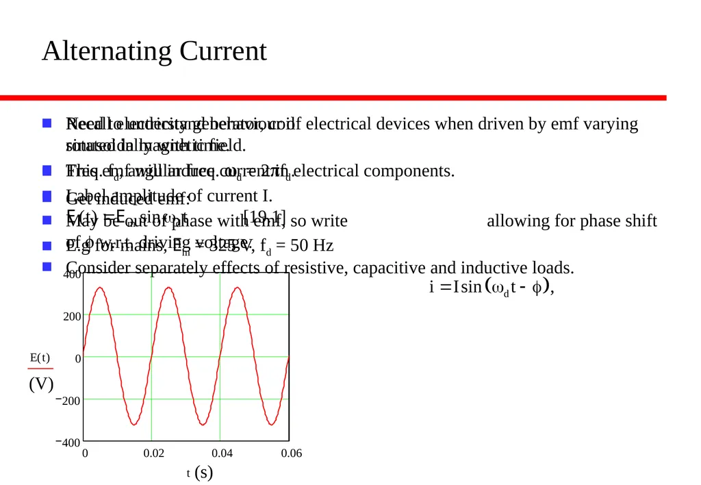
slide2. Alternating Current Recall electricity generator, coil rotated in magnetic field.
Freq. fd, angular freq. wd = 2pfd.
Get induced emf:
E.g for mains, Em = 325 V, fd = 50 Hz Need to understand behaviour of electrical devices when driven by emf varying sinusoidally with time.
This emf will induce current in electrical components.
Label amplitude of current I.
May be out of phase with emf, so write allowing for phase shift of f w.r.t. driving voltage.
Consider separately effects of resistive, capacitive and inductive loads.<br>
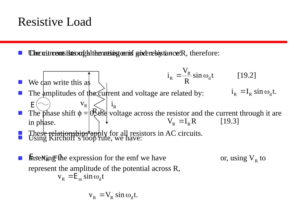
slide3. Resistive Load Circuit consists of alternating emf and resistance:
Using Kirchoff’s loop rule, we have:
Inserting the expression for the emf we have or, using VR to represent the amplitude of the potential across R, The current through the resistor is given by i = v/R, therefore:
We can write this as
The amplitudes of the current and voltage are related by:
The phase shift f = 0: the voltage across the resistor and the current through it are in phase.
These relationships apply for all resistors in AC circuits.<br>
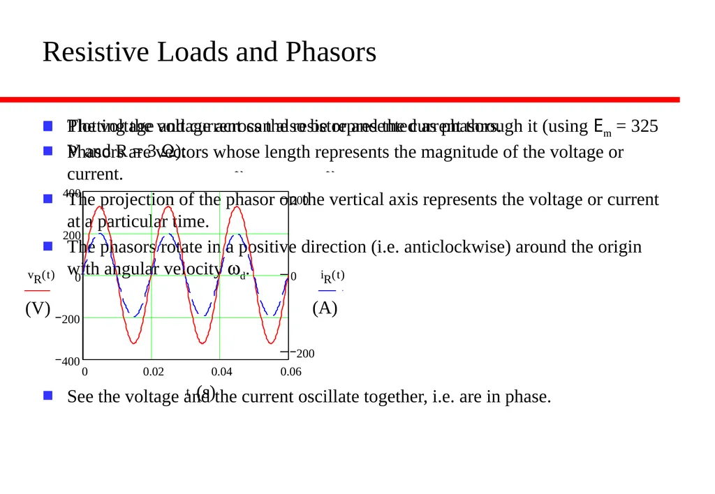
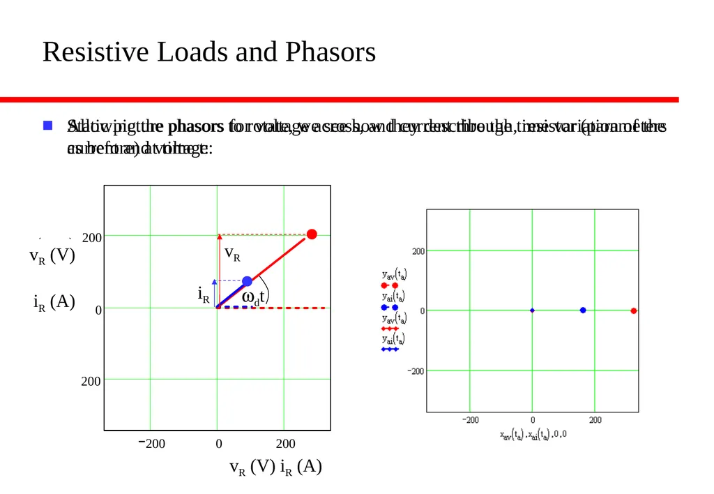
slide4. Resistive Loads and Phasors Plotting the voltage across the resistor and the current through it (using Em = 325 V and R = 3 W):
See the voltage and the current oscillate together, i.e. are in phase. The voltage and current can also be represented as phasors.
Phasors are vectors whose length represents the magnitude of the voltage or current.
The projection of the phasor on the vertical axis represents the voltage or current at a particular time.
The phasors rotate in a positive direction (i.e. anticlockwise) around the origin with angular velocity wd.<br>
slide5. Resistive Loads and Phasors Static picture phasors for voltage across, and current through, resistor (parameters as before) at time t: Allowing the phasors to rotate, we see how they describe the time variation of the current and voltage:<br>
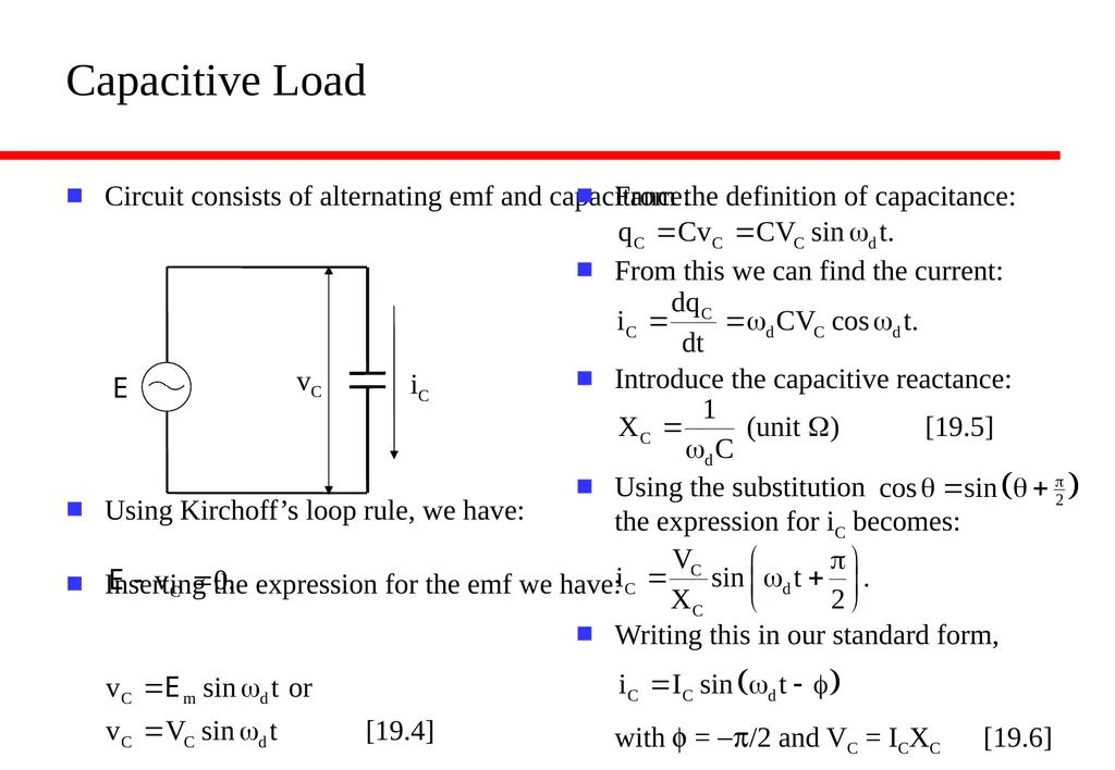
slide6. Capacitive Load Circuit consists of alternating emf and capacitance:
Using Kirchoff’s loop rule, we have:
Inserting the expression for the emf we have: From the definition of capacitance:
From this we can find the current:
Introduce the capacitive reactance:
Using the substitution the expression for iC becomes:
Writing this in our standard form, with f = -p/2 and VC = ICXC [19.6]<br>
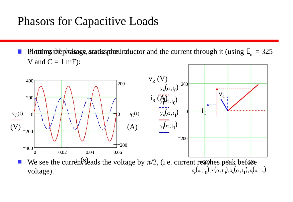
slide7. Phasors for Capacitive Loads Plotting the voltage across the inductor and the current through it (using Em = 325 V and C = 1 mF):
We see the current leads the voltage by p/2, (i.e. current reaches peak before voltage). In terms of phasors, static picture:<br>
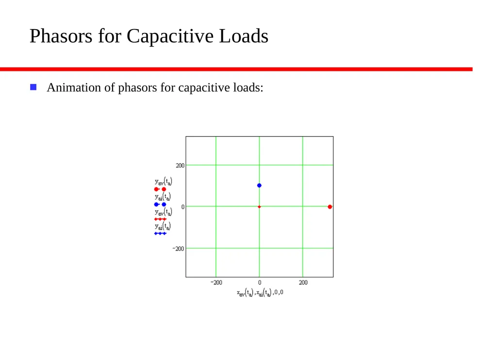
slide8. Phasors for Capacitive Loads Animation of phasors for capacitive loads:<br>
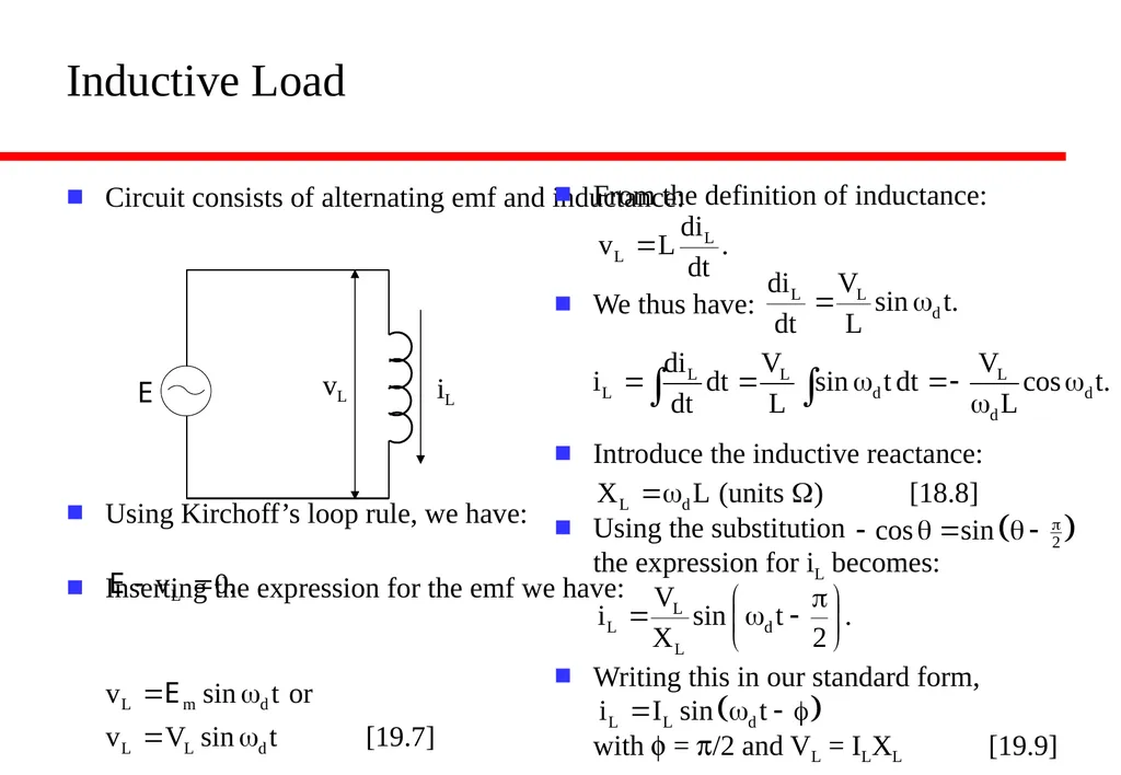
slide9. Inductive Load Circuit consists of alternating emf and inductance:
Using Kirchoff’s loop rule, we have:
Inserting the expression for the emf we have: From the definition of inductance:
We thus have:
Introduce the inductive reactance:
Using the substitution the expression for iL becomes:
Writing this in our standard form, with f = p/2 and VL = ILXL [19.9]<br>
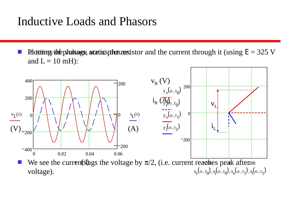
slide10. Inductive Loads and Phasors Plotting the voltage across the resistor and the current through it (using E = 325 V and L = 10 mH):
We see the current lags the voltage by p/2, (i.e. current reaches peak after voltage). In terms of phasors, static picture: (V) (s) (A)<br>
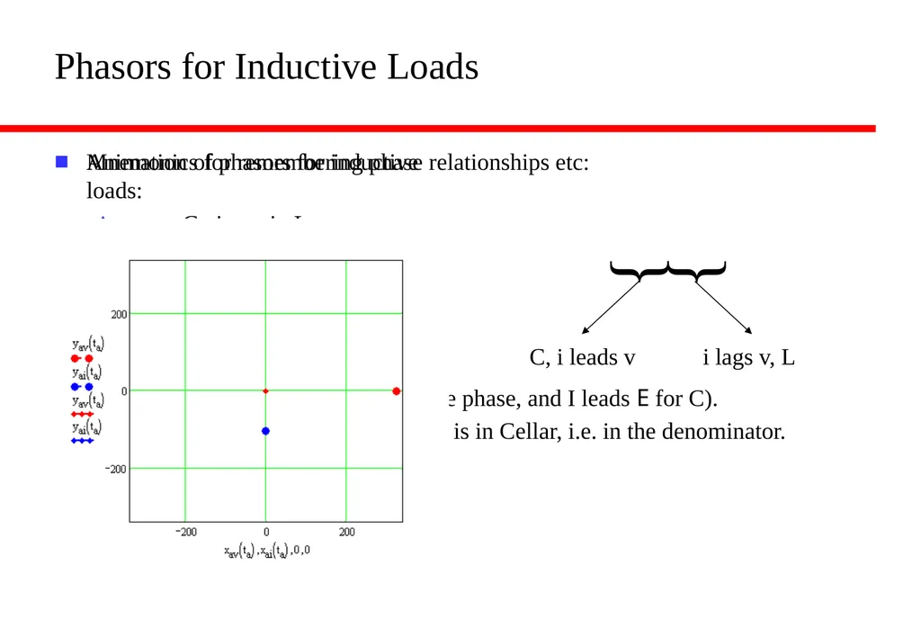
slide11. Phasors for Inductive Loads Animation of phasors for inductive loads: Mnemonics for remembering phase relationships etc:
C i v i L
ELI positively is the ICE man. (i.e. E leads I for L, which has +ive phase, and I leads E for C).
XC = wdC or 1/wdC? Remember that C is in Cellar, i.e. in the denominator.<br>
Alternating current.
Resistive loads and phasors.
Capacitive loads and phasors.
Inductive loads and phasors. After this lecture, you should be able to answer the following questions:
Write down the equations which define the capacitive and inductive reactances. In what units are these measured?
Is the reactance of a capacitor largest for high or low frequencies?
Is the reactance of an inductor largest for high or low frequencies?
Describe the phase relationships between an AC voltage applied (separately) across a resistor, a capacitor and an inductance and the resulting current in each case.<br>
slide2. Alternating Current Recall electricity generator, coil rotated in magnetic field.
Freq. fd, angular freq. wd = 2pfd.
Get induced emf:
E.g for mains, Em = 325 V, fd = 50 Hz Need to understand behaviour of electrical devices when driven by emf varying sinusoidally with time.
This emf will induce current in electrical components.
Label amplitude of current I.
May be out of phase with emf, so write allowing for phase shift of f w.r.t. driving voltage.
Consider separately effects of resistive, capacitive and inductive loads.<br>
slide3. Resistive Load Circuit consists of alternating emf and resistance:
Using Kirchoff’s loop rule, we have:
Inserting the expression for the emf we have or, using VR to represent the amplitude of the potential across R, The current through the resistor is given by i = v/R, therefore:
We can write this as
The amplitudes of the current and voltage are related by:
The phase shift f = 0: the voltage across the resistor and the current through it are in phase.
These relationships apply for all resistors in AC circuits.<br>
slide4. Resistive Loads and Phasors Plotting the voltage across the resistor and the current through it (using Em = 325 V and R = 3 W):
See the voltage and the current oscillate together, i.e. are in phase. The voltage and current can also be represented as phasors.
Phasors are vectors whose length represents the magnitude of the voltage or current.
The projection of the phasor on the vertical axis represents the voltage or current at a particular time.
The phasors rotate in a positive direction (i.e. anticlockwise) around the origin with angular velocity wd.<br>
slide5. Resistive Loads and Phasors Static picture phasors for voltage across, and current through, resistor (parameters as before) at time t: Allowing the phasors to rotate, we see how they describe the time variation of the current and voltage:<br>
slide6. Capacitive Load Circuit consists of alternating emf and capacitance:
Using Kirchoff’s loop rule, we have:
Inserting the expression for the emf we have: From the definition of capacitance:
From this we can find the current:
Introduce the capacitive reactance:
Using the substitution the expression for iC becomes:
Writing this in our standard form, with f = -p/2 and VC = ICXC [19.6]<br>
slide7. Phasors for Capacitive Loads Plotting the voltage across the inductor and the current through it (using Em = 325 V and C = 1 mF):
We see the current leads the voltage by p/2, (i.e. current reaches peak before voltage). In terms of phasors, static picture:<br>
slide8. Phasors for Capacitive Loads Animation of phasors for capacitive loads:<br>
slide9. Inductive Load Circuit consists of alternating emf and inductance:
Using Kirchoff’s loop rule, we have:
Inserting the expression for the emf we have: From the definition of inductance:
We thus have:
Introduce the inductive reactance:
Using the substitution the expression for iL becomes:
Writing this in our standard form, with f = p/2 and VL = ILXL [19.9]<br>
slide10. Inductive Loads and Phasors Plotting the voltage across the resistor and the current through it (using E = 325 V and L = 10 mH):
We see the current lags the voltage by p/2, (i.e. current reaches peak after voltage). In terms of phasors, static picture: (V) (s) (A)<br>
slide11. Phasors for Inductive Loads Animation of phasors for inductive loads: Mnemonics for remembering phase relationships etc:
C i v i L
ELI positively is the ICE man. (i.e. E leads I for L, which has +ive phase, and I leads E for C).
XC = wdC or 1/wdC? Remember that C is in Cellar, i.e. in the denominator.<br>