Modeling in Electrochemical Engineering Your Name
Description: Modeling in Electrochemical Engineering Your Name Introduction: Electrochemical Systems Electrochemical systems are devices or processes in which an ionic conductor mediates the inter-conversion of chemical and electrical energy The
Related Topics
Download Presentation
"Modeling in Electrochemical Engineering Your Name" is the property of its rightful owner. Permission is granted to download and print the materials on this website for personal, non-commercial use only, and to display it on your personal computer provided you do not modify the materials and that you retain all copyright notices contained in the materials. By downloading content from our website, you accept the terms of this agreement.
Presentation Transcript
slide1. Modeling in Electrochemical Engineering Your Name<br>
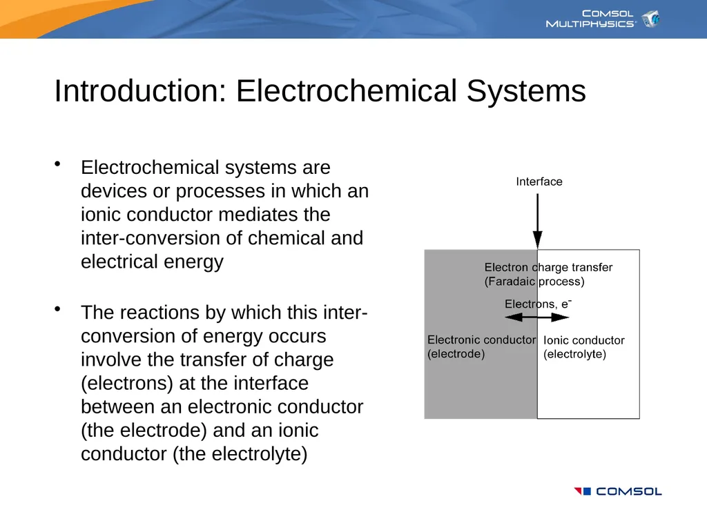
slide2. Introduction: Electrochemical Systems Electrochemical systems are devices or processes in which an ionic conductor mediates the inter-conversion of chemical and electrical energy
The reactions by which this inter-conversion of energy occurs involve the transfer of charge (electrons) at the interface between an electronic conductor (the electrode) and an ionic conductor (the electrolyte)<br>
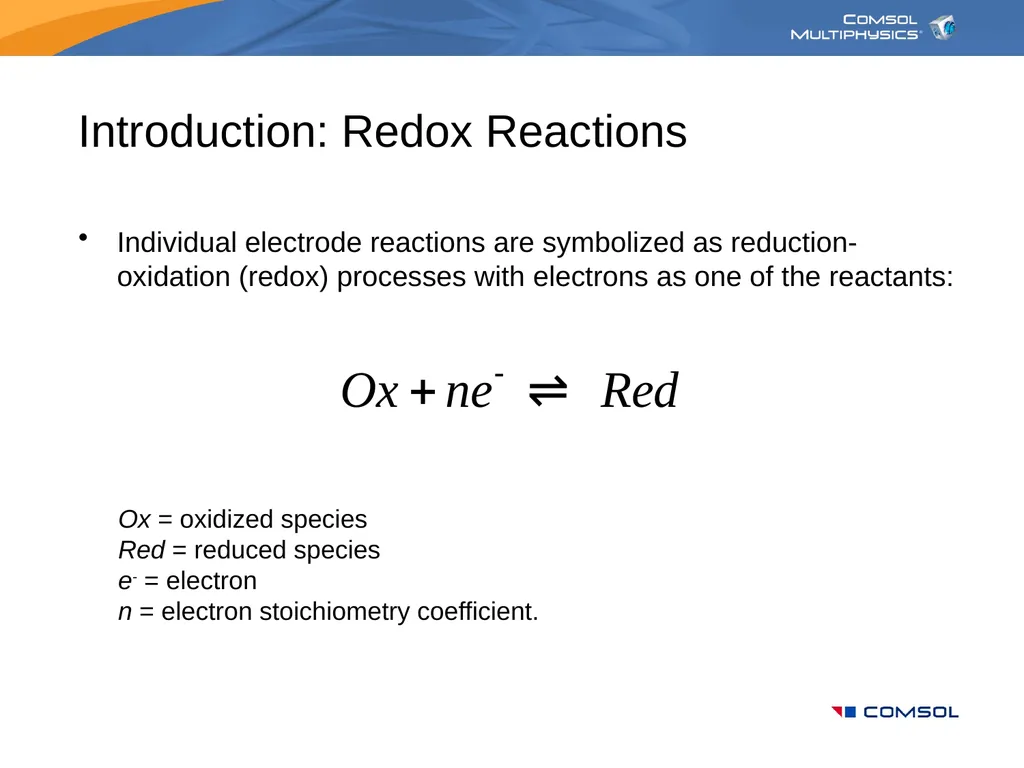
slide3. Introduction: Redox Reactions Individual electrode reactions are symbolized as reduction-oxidation (redox) processes with electrons as one of the reactants: Ox = oxidized species
Red = reduced species
e- = electron
n = electron stoichiometry coefficient.<br>
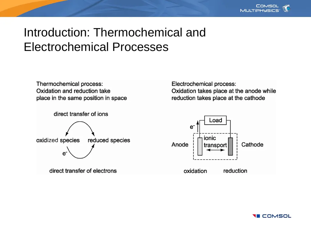
slide4. Introduction: Thermochemical and Electrochemical Processes<br>
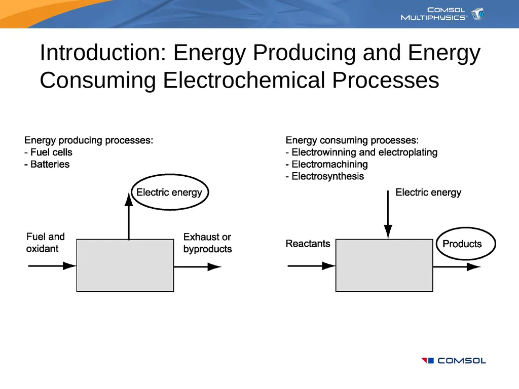
slide5. Introduction: Energy Producing and Energy Consuming Electrochemical Processes<br>
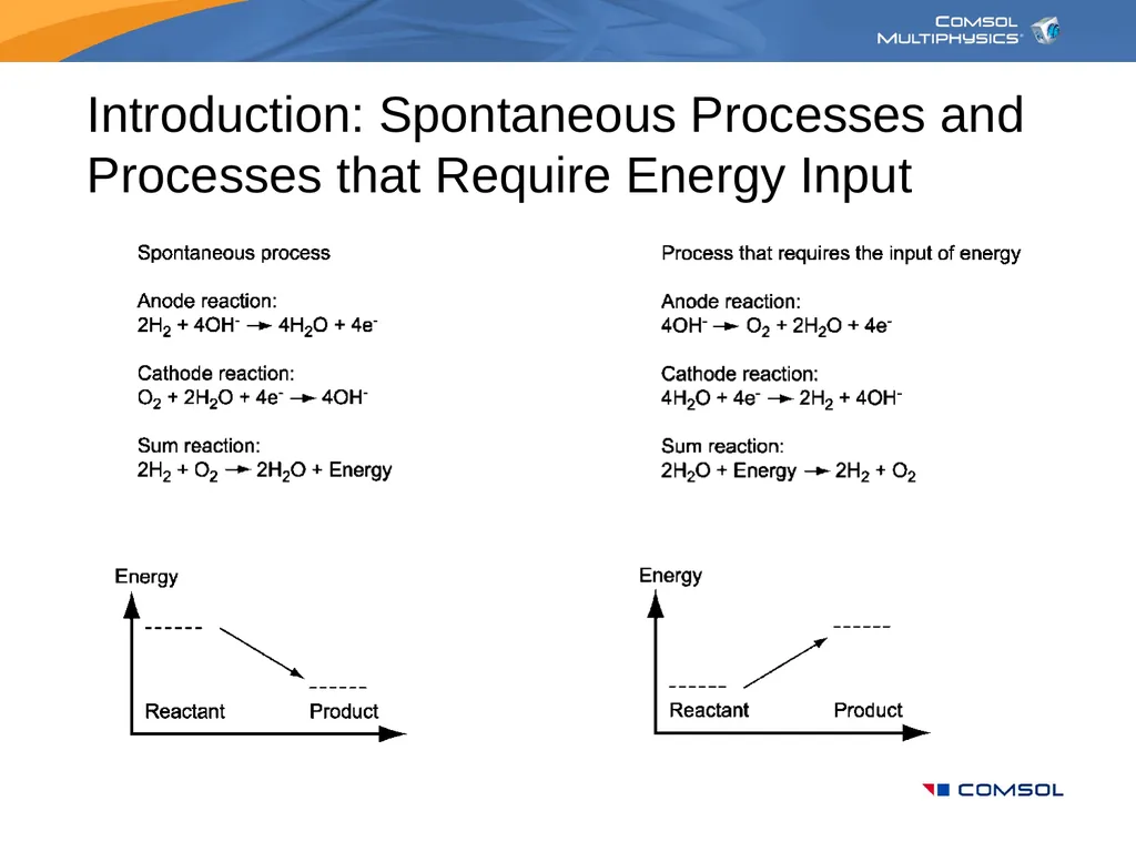
slide6. Introduction: Spontaneous Processes and Processes that Require Energy Input<br>
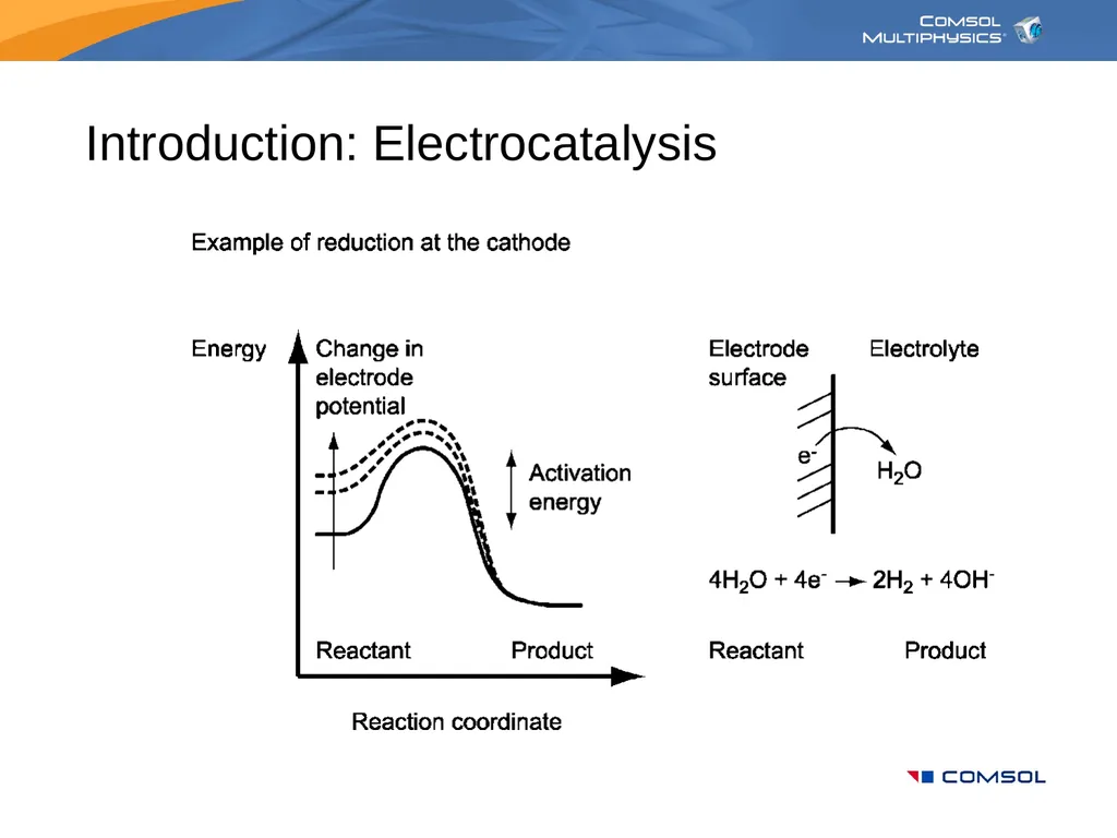
slide7. Introduction: Electrocatalysis<br>
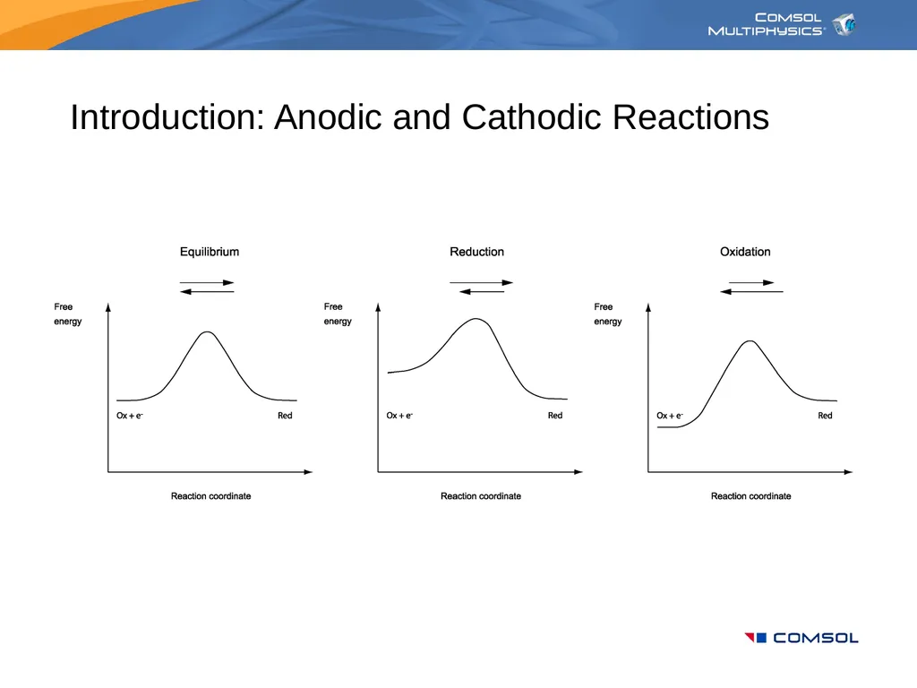
slide8. Introduction: Anodic and Cathodic Reactions<br>
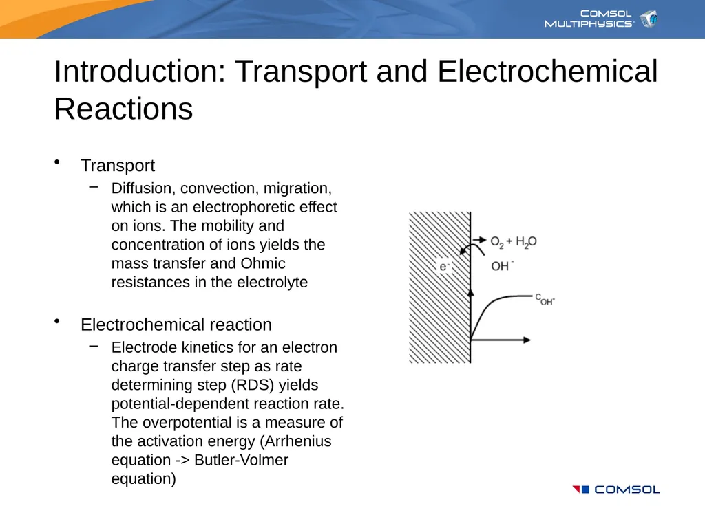
slide9. Introduction: Transport and Electrochemical Reactions Transport
Diffusion, convection, migration, which is an electrophoretic effect on ions. The mobility and concentration of ions yields the mass transfer and Ohmic resistances in the electrolyte
Electrochemical reaction
Electrode kinetics for an electron charge transfer step as rate determining step (RDS) yields potential-dependent reaction rate. The overpotential is a measure of the activation energy (Arrhenius equation -> Butler-Volmer equation)<br>
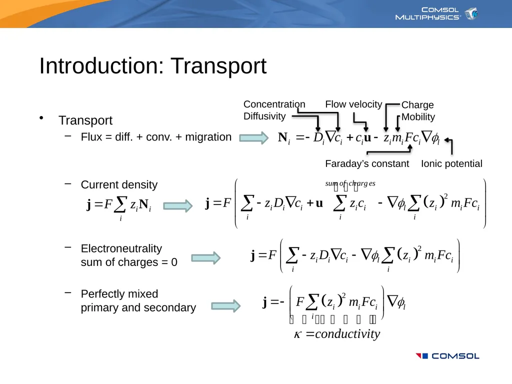
slide10. Introduction: Transport Transport
Flux = diff. + conv. + migration
Current density
Electroneutralitysum of charges = 0
Perfectly mixedprimary and secondary Concentration
Diffusivity Flow velocity Charge
Mobility Ionic potential Faraday’s constant<br>
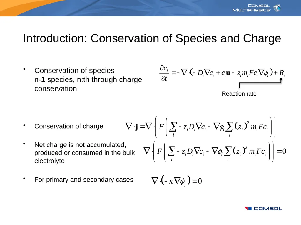
slide11. Introduction: Conservation of Species and Charge Conservation of speciesn-1 species, n:th through chargeconservation
Conservation of charge
Net charge is not accumulated, produced or consumed in the bulk electrolyte
For primary and secondary cases Reaction rate<br>
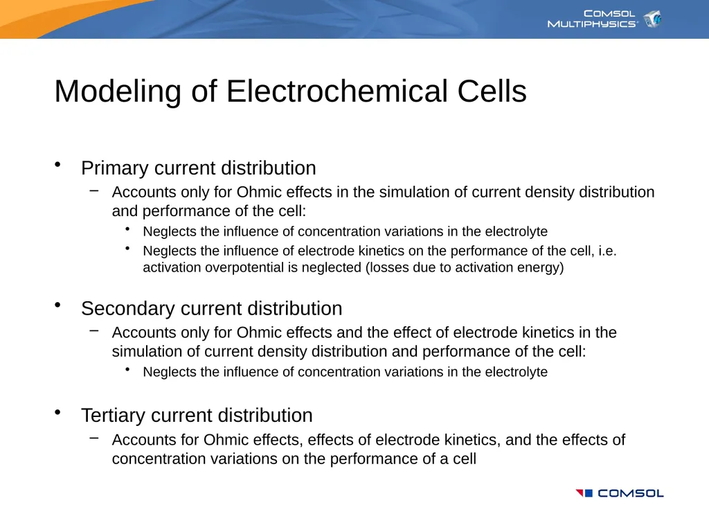
slide12. Modeling of Electrochemical Cells Primary current distribution
Accounts only for Ohmic effects in the simulation of current density distribution and performance of the cell:
Neglects the influence of concentration variations in the electrolyte
Neglects the influence of electrode kinetics on the performance of the cell, i.e. activation overpotential is neglected (losses due to activation energy)
Secondary current distribution
Accounts only for Ohmic effects and the effect of electrode kinetics in the simulation of current density distribution and performance of the cell:
Neglects the influence of concentration variations in the electrolyte
Tertiary current distribution
Accounts for Ohmic effects, effects of electrode kinetics, and the effects of concentration variations on the performance of a cell<br>
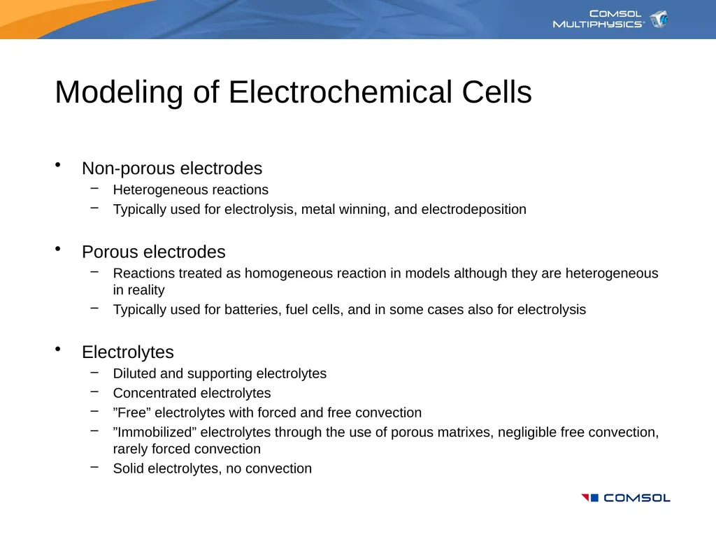
slide13. Modeling of Electrochemical Cells Non-porous electrodes
Heterogeneous reactions
Typically used for electrolysis, metal winning, and electrodeposition
Porous electrodes
Reactions treated as homogeneous reaction in models although they are heterogeneous in reality
Typically used for batteries, fuel cells, and in some cases also for electrolysis
Electrolytes
Diluted and supporting electrolytes
Concentrated electrolytes
”Free” electrolytes with forced and free convection
”Immobilized” electrolytes through the use of porous matrixes, negligible free convection, rarely forced convection
Solid electrolytes, no convection<br>
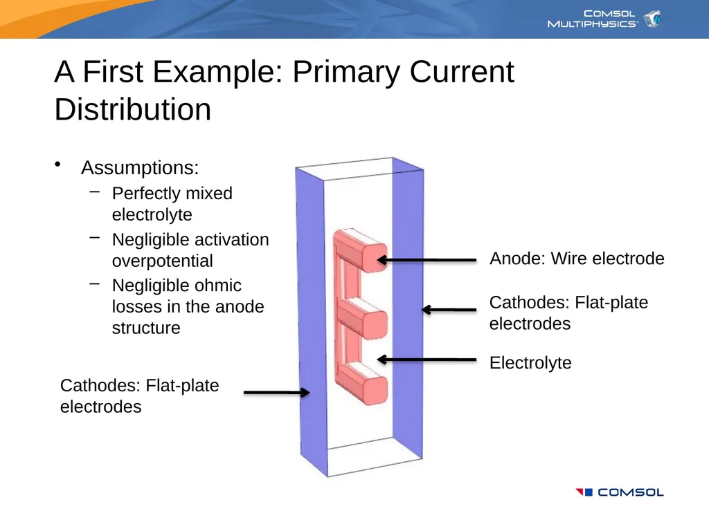
slide14. Assumptions:
Perfectly mixed electrolyte
Negligible activation overpotential
Negligible ohmic losses in the anode structure A First Example: Primary Current Distribution Anode: Wire electrode Cathodes: Flat-plateelectrodes Cathodes: Flat-plateelectrodes Electrolyte<br>
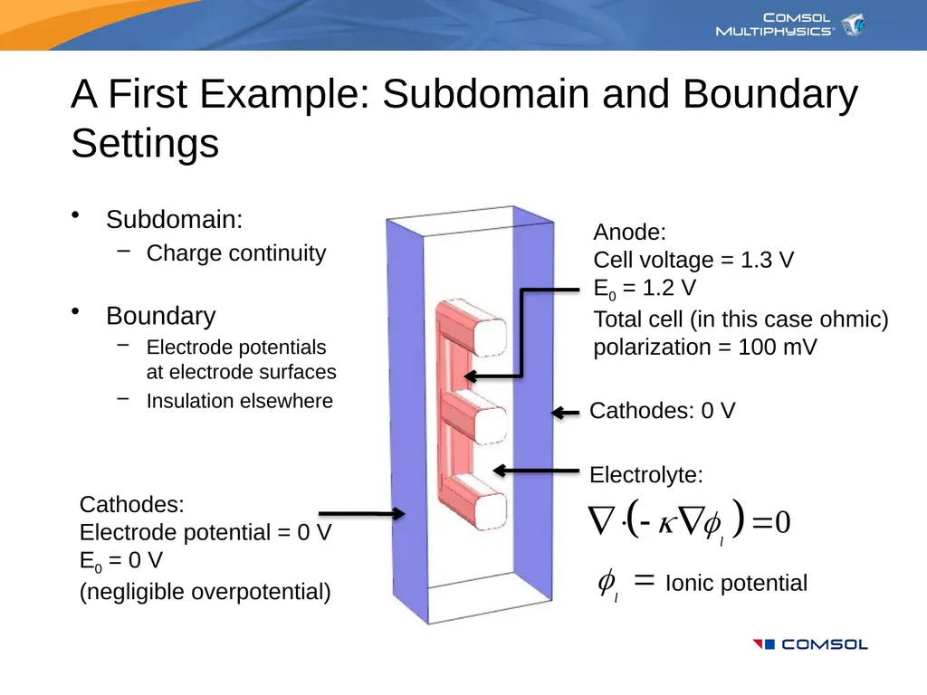
slide15. Subdomain:
Charge continuity
Boundary
Electrode potentialsat electrode surfaces
Insulation elsewhere A First Example: Subdomain and Boundary Settings Anode: Cell voltage = 1.3 V
E0 = 1.2 V
Total cell (in this case ohmic) polarization = 100 mV Cathodes:
Electrode potential = 0 V
E0 = 0 V
(negligible overpotential) Cathodes: 0 V Electrolyte: Ionic potential<br>
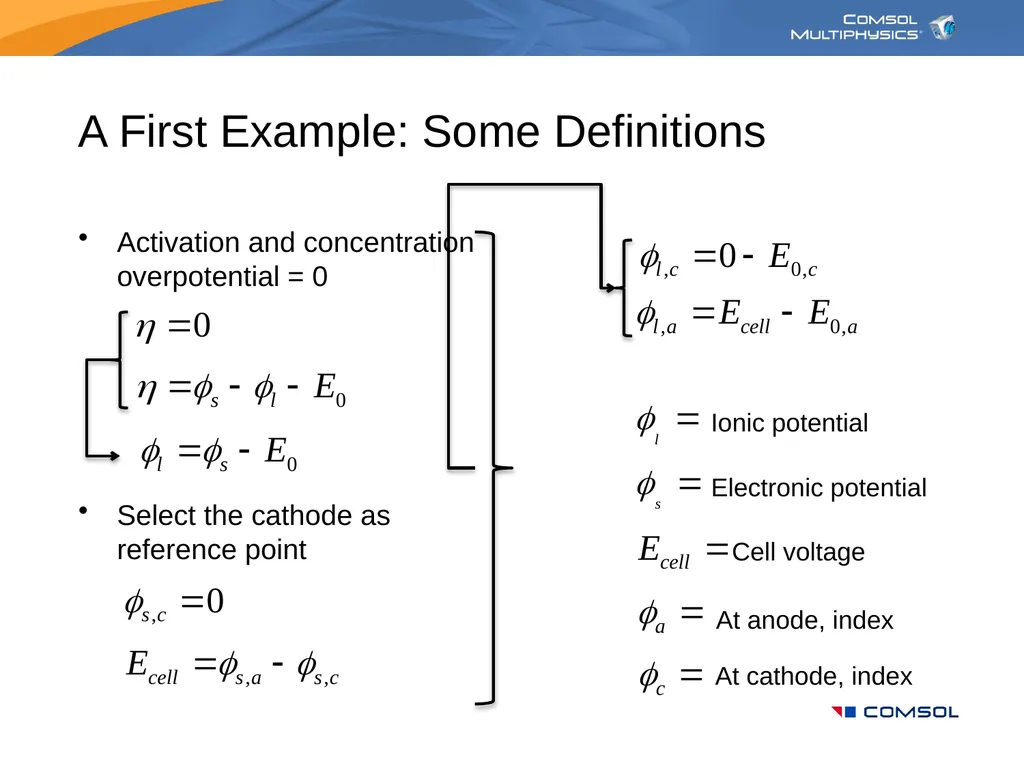
slide16. A First Example: Some Definitions Activation and concentration overpotential = 0
Select the cathode as reference point Electronic potential Cell voltage Ionic potential At anode, index At cathode, index<br>
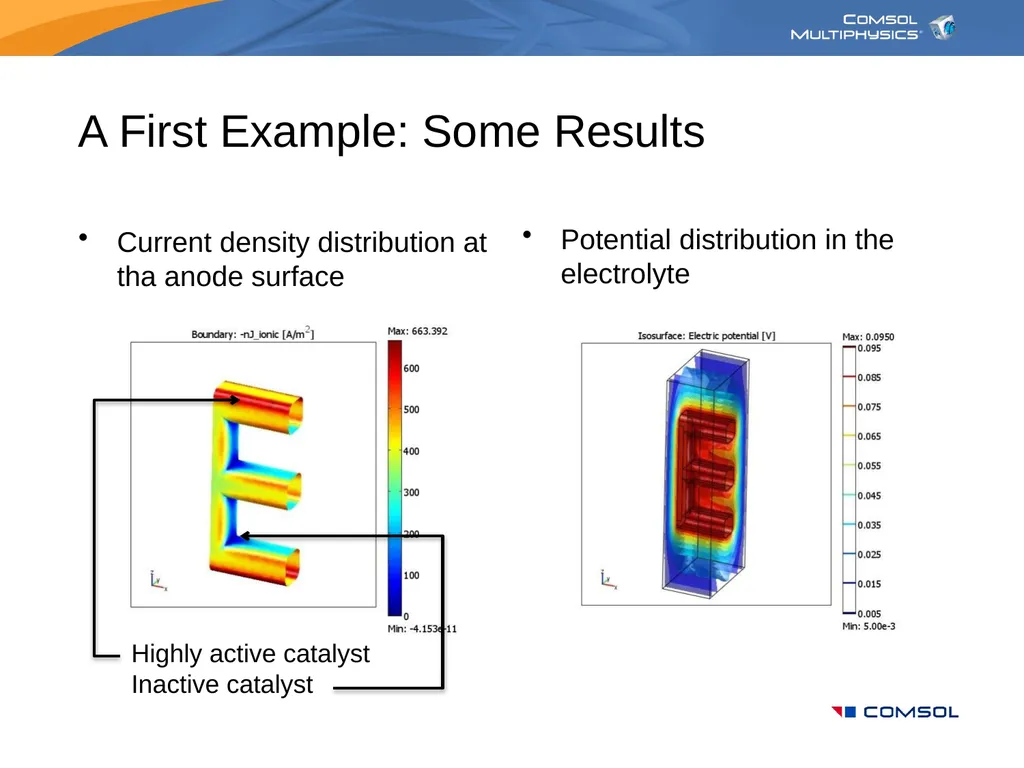
slide17. A First Example: Some Results Current density distribution at tha anode surface Highly active catalyst
Inactive catalyst Potential distribution in the electrolyte<br>
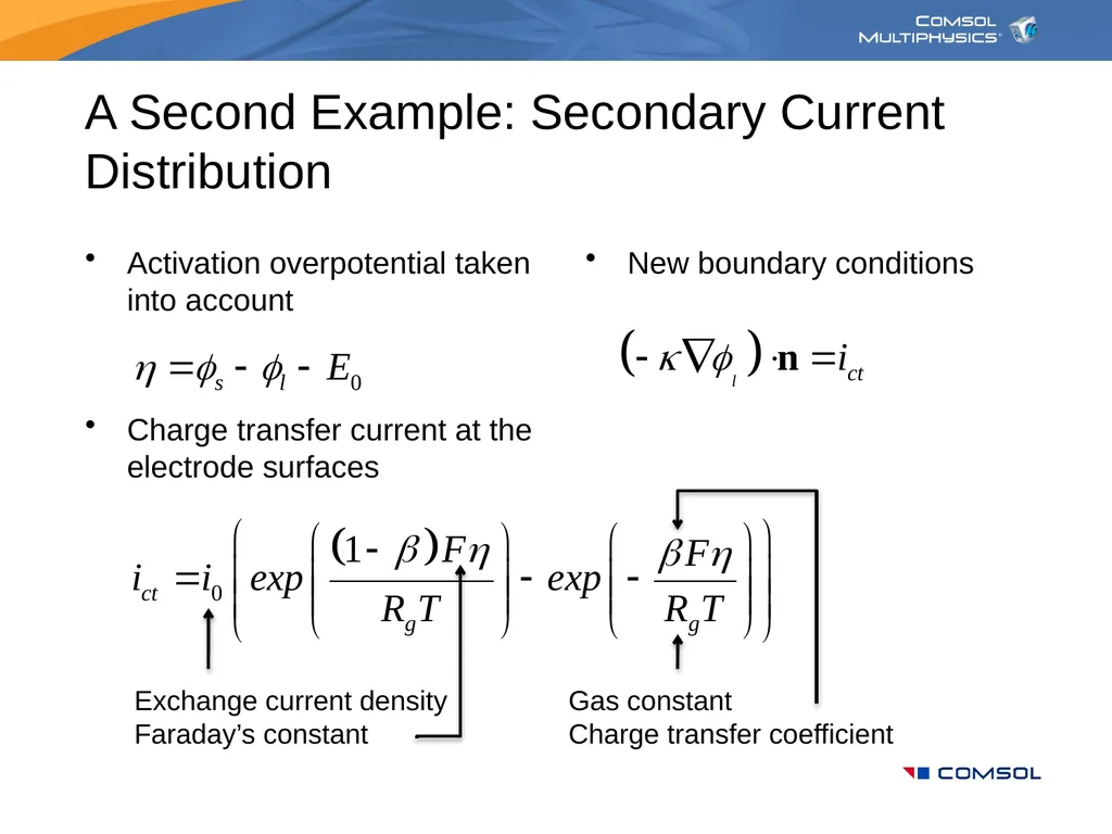
slide18. A Second Example: Secondary Current Distribution Activation overpotential taken into account
Charge transfer current at the electrode surfaces New boundary conditions Exchange current density
Faraday’s constant Gas constant
Charge transfer coefficient<br>
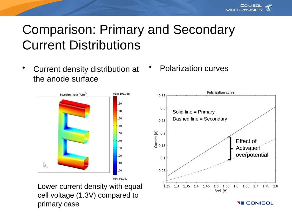
slide19. Comparison: Primary and Secondary Current Distributions Current density distribution at the anode surface Lower current density with equal cell voltage (1.3V) compared to primary case Polarization curves Effect of
Activation
overpotential Solid line = Primary Dashed line = Secondary<br>
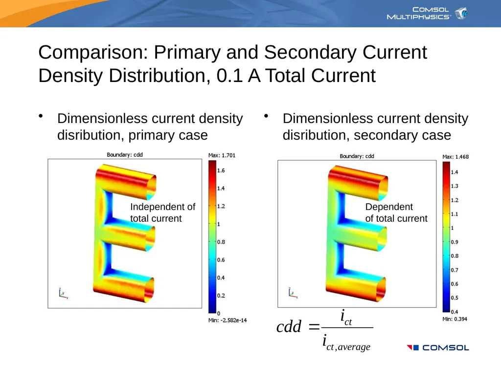
slide20. Comparison: Primary and Secondary Current Density Distribution, 0.1 A Total Current Dimensionless current density disribution, primary case Dimensionless current density disribution, secondary case Independent of total current Dependent
of total current<br>
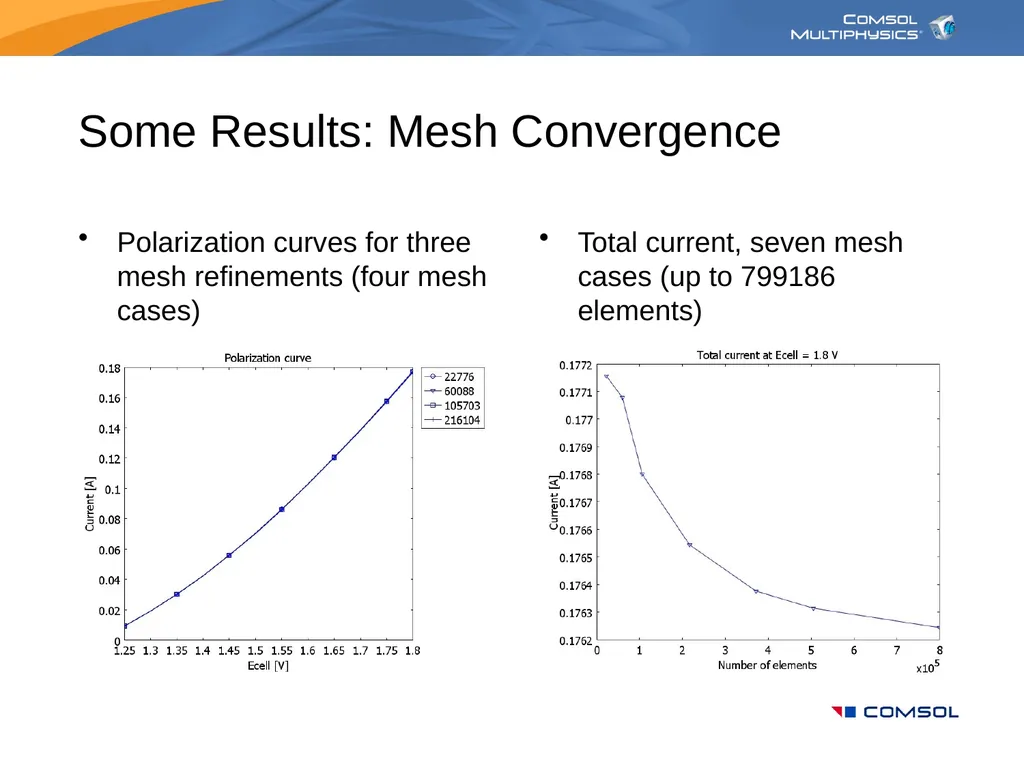
slide21. Some Results: Mesh Convergence Polarization curves for three mesh refinements (four mesh cases) Total current, seven mesh cases (up to 799186 elements)<br>
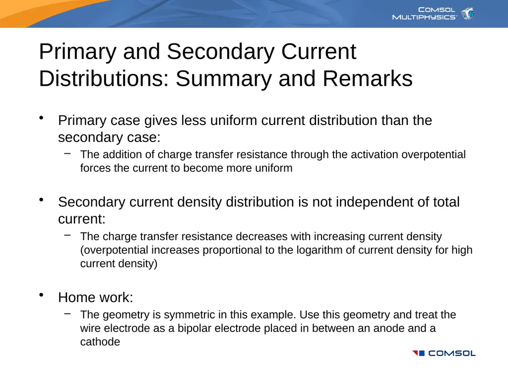
slide22. Primary and Secondary Current Distributions: Summary and Remarks Primary case gives less uniform current distribution than the secondary case:
The addition of charge transfer resistance through the activation overpotential forces the current to become more uniform
Secondary current density distribution is not independent of total current:
The charge transfer resistance decreases with increasing current density (overpotential increases proportional to the logarithm of current density for high current density)
Home work:
The geometry is symmetric in this example. Use this geometry and treat the wire electrode as a bipolar electrode placed in between an anode and a cathode<br>
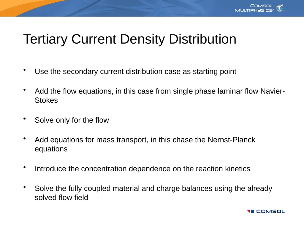
slide23. Tertiary Current Density Distribution Use the secondary current distribution case as starting point
Add the flow equations, in this case from single phase laminar flow Navier-Stokes
Solve only for the flow
Add equations for mass transport, in this chase the Nernst-Planck equations
Introduce the concentration dependence on the reaction kinetics
Solve the fully coupled material and charge balances using the already solved flow field<br>
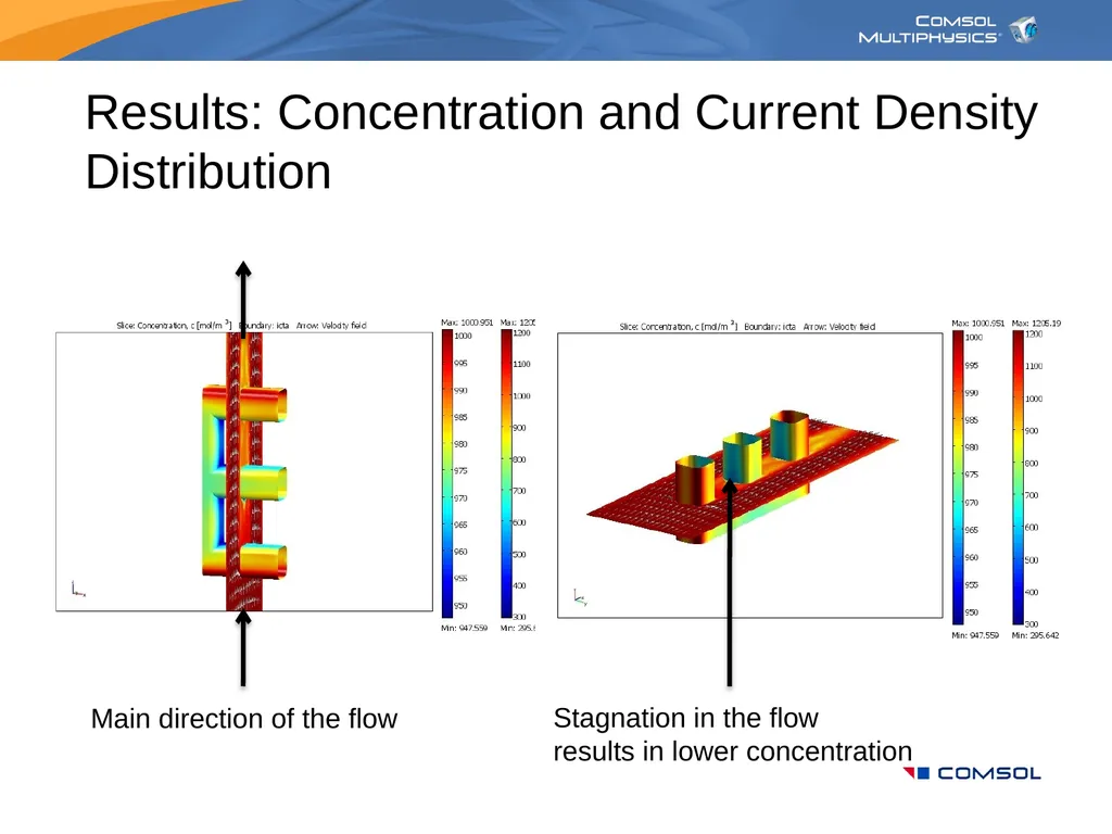
slide24. Results: Concentration and Current Density Distribution Main direction of the flow Stagnation in the flowresults in lower concentration<br>
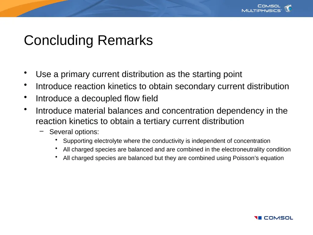
slide25. Concluding Remarks Use a primary current distribution as the starting point
Introduce reaction kinetics to obtain secondary current distribution
Introduce a decoupled flow field
Introduce material balances and concentration dependency in the reaction kinetics to obtain a tertiary current distribution
Several options:
Supporting electrolyte where the conductivity is independent of concentration
All charged species are balanced and are combined in the electroneutrality condition
All charged species are balanced but they are combined using Poisson’s equation<br>

slide2. Introduction: Electrochemical Systems Electrochemical systems are devices or processes in which an ionic conductor mediates the inter-conversion of chemical and electrical energy
The reactions by which this inter-conversion of energy occurs involve the transfer of charge (electrons) at the interface between an electronic conductor (the electrode) and an ionic conductor (the electrolyte)<br>
slide3. Introduction: Redox Reactions Individual electrode reactions are symbolized as reduction-oxidation (redox) processes with electrons as one of the reactants: Ox = oxidized species
Red = reduced species
e- = electron
n = electron stoichiometry coefficient.<br>
slide4. Introduction: Thermochemical and Electrochemical Processes<br>
slide5. Introduction: Energy Producing and Energy Consuming Electrochemical Processes<br>
slide6. Introduction: Spontaneous Processes and Processes that Require Energy Input<br>
slide7. Introduction: Electrocatalysis<br>
slide8. Introduction: Anodic and Cathodic Reactions<br>
slide9. Introduction: Transport and Electrochemical Reactions Transport
Diffusion, convection, migration, which is an electrophoretic effect on ions. The mobility and concentration of ions yields the mass transfer and Ohmic resistances in the electrolyte
Electrochemical reaction
Electrode kinetics for an electron charge transfer step as rate determining step (RDS) yields potential-dependent reaction rate. The overpotential is a measure of the activation energy (Arrhenius equation -> Butler-Volmer equation)<br>
slide10. Introduction: Transport Transport
Flux = diff. + conv. + migration
Current density
Electroneutralitysum of charges = 0
Perfectly mixedprimary and secondary Concentration
Diffusivity Flow velocity Charge
Mobility Ionic potential Faraday’s constant<br>
slide11. Introduction: Conservation of Species and Charge Conservation of speciesn-1 species, n:th through chargeconservation
Conservation of charge
Net charge is not accumulated, produced or consumed in the bulk electrolyte
For primary and secondary cases Reaction rate<br>
slide12. Modeling of Electrochemical Cells Primary current distribution
Accounts only for Ohmic effects in the simulation of current density distribution and performance of the cell:
Neglects the influence of concentration variations in the electrolyte
Neglects the influence of electrode kinetics on the performance of the cell, i.e. activation overpotential is neglected (losses due to activation energy)
Secondary current distribution
Accounts only for Ohmic effects and the effect of electrode kinetics in the simulation of current density distribution and performance of the cell:
Neglects the influence of concentration variations in the electrolyte
Tertiary current distribution
Accounts for Ohmic effects, effects of electrode kinetics, and the effects of concentration variations on the performance of a cell<br>
slide13. Modeling of Electrochemical Cells Non-porous electrodes
Heterogeneous reactions
Typically used for electrolysis, metal winning, and electrodeposition
Porous electrodes
Reactions treated as homogeneous reaction in models although they are heterogeneous in reality
Typically used for batteries, fuel cells, and in some cases also for electrolysis
Electrolytes
Diluted and supporting electrolytes
Concentrated electrolytes
”Free” electrolytes with forced and free convection
”Immobilized” electrolytes through the use of porous matrixes, negligible free convection, rarely forced convection
Solid electrolytes, no convection<br>
slide14. Assumptions:
Perfectly mixed electrolyte
Negligible activation overpotential
Negligible ohmic losses in the anode structure A First Example: Primary Current Distribution Anode: Wire electrode Cathodes: Flat-plateelectrodes Cathodes: Flat-plateelectrodes Electrolyte<br>
slide15. Subdomain:
Charge continuity
Boundary
Electrode potentialsat electrode surfaces
Insulation elsewhere A First Example: Subdomain and Boundary Settings Anode: Cell voltage = 1.3 V
E0 = 1.2 V
Total cell (in this case ohmic) polarization = 100 mV Cathodes:
Electrode potential = 0 V
E0 = 0 V
(negligible overpotential) Cathodes: 0 V Electrolyte: Ionic potential<br>
slide16. A First Example: Some Definitions Activation and concentration overpotential = 0
Select the cathode as reference point Electronic potential Cell voltage Ionic potential At anode, index At cathode, index<br>
slide17. A First Example: Some Results Current density distribution at tha anode surface Highly active catalyst
Inactive catalyst Potential distribution in the electrolyte<br>
slide18. A Second Example: Secondary Current Distribution Activation overpotential taken into account
Charge transfer current at the electrode surfaces New boundary conditions Exchange current density
Faraday’s constant Gas constant
Charge transfer coefficient<br>
slide19. Comparison: Primary and Secondary Current Distributions Current density distribution at the anode surface Lower current density with equal cell voltage (1.3V) compared to primary case Polarization curves Effect of
Activation
overpotential Solid line = Primary Dashed line = Secondary<br>
slide20. Comparison: Primary and Secondary Current Density Distribution, 0.1 A Total Current Dimensionless current density disribution, primary case Dimensionless current density disribution, secondary case Independent of total current Dependent
of total current<br>
slide21. Some Results: Mesh Convergence Polarization curves for three mesh refinements (four mesh cases) Total current, seven mesh cases (up to 799186 elements)<br>
slide22. Primary and Secondary Current Distributions: Summary and Remarks Primary case gives less uniform current distribution than the secondary case:
The addition of charge transfer resistance through the activation overpotential forces the current to become more uniform
Secondary current density distribution is not independent of total current:
The charge transfer resistance decreases with increasing current density (overpotential increases proportional to the logarithm of current density for high current density)
Home work:
The geometry is symmetric in this example. Use this geometry and treat the wire electrode as a bipolar electrode placed in between an anode and a cathode<br>
slide23. Tertiary Current Density Distribution Use the secondary current distribution case as starting point
Add the flow equations, in this case from single phase laminar flow Navier-Stokes
Solve only for the flow
Add equations for mass transport, in this chase the Nernst-Planck equations
Introduce the concentration dependence on the reaction kinetics
Solve the fully coupled material and charge balances using the already solved flow field<br>
slide24. Results: Concentration and Current Density Distribution Main direction of the flow Stagnation in the flowresults in lower concentration<br>
slide25. Concluding Remarks Use a primary current distribution as the starting point
Introduce reaction kinetics to obtain secondary current distribution
Introduce a decoupled flow field
Introduce material balances and concentration dependency in the reaction kinetics to obtain a tertiary current distribution
Several options:
Supporting electrolyte where the conductivity is independent of concentration
All charged species are balanced and are combined in the electroneutrality condition
All charged species are balanced but they are combined using Poisson’s equation<br>