04
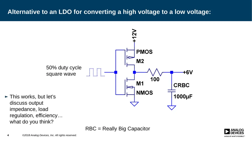
Alternative to an LDO for converting a high voltage to a low voltage: This works, but let’s discuss output impedance, load regulation, efficiency… what do you think? 4 ©2018 Analog Devices, Inc. All rights reserved. 50% duty cycle square wave RBC = Really Big Capacitor<br>
05
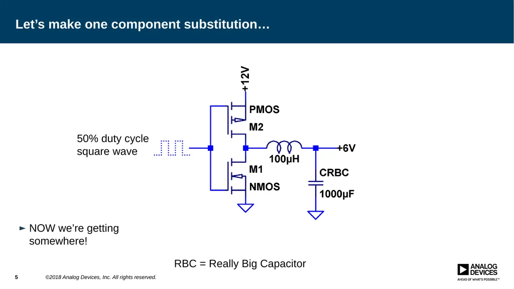
Let’s make one component substitution… NOW we’re getting somewhere! 5 ©2018 Analog Devices, Inc. All rights reserved. 50% duty cycle square wave RBC = Really Big Capacitor<br>
06
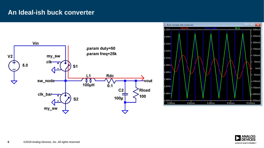
An Ideal-ish buck converter 6 ©2018 Analog Devices, Inc. All rights reserved.<br>
07
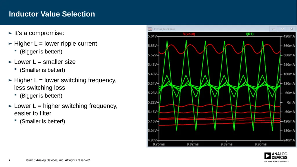
Inductor Value Selection It’s a compromise:
Higher L = lower ripple current
(Bigger is better!)
Lower L = smaller size
(Smaller is better!)
Higher L = lower switching frequency, less switching loss
(Bigger is better!)
Lower L = higher switching frequency, easier to filter
(Smaller is better!) 7 ©2018 Analog Devices, Inc. All rights reserved.<br>
08
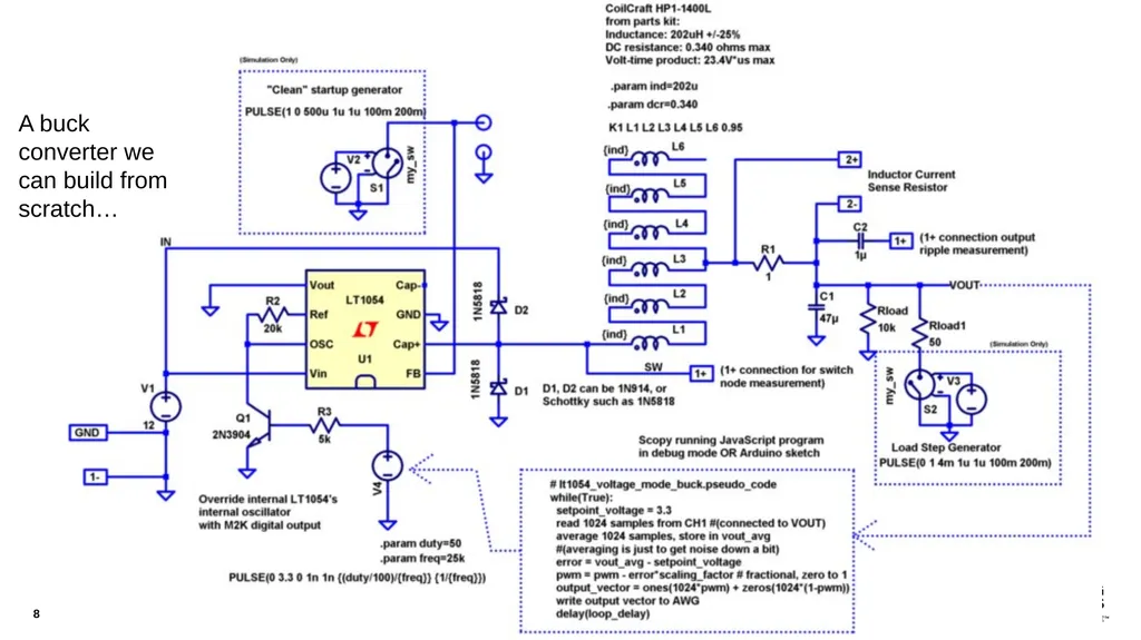
8 ©2018 Analog Devices, Inc. All rights reserved. A buck converter we can build from scratch…<br>
09
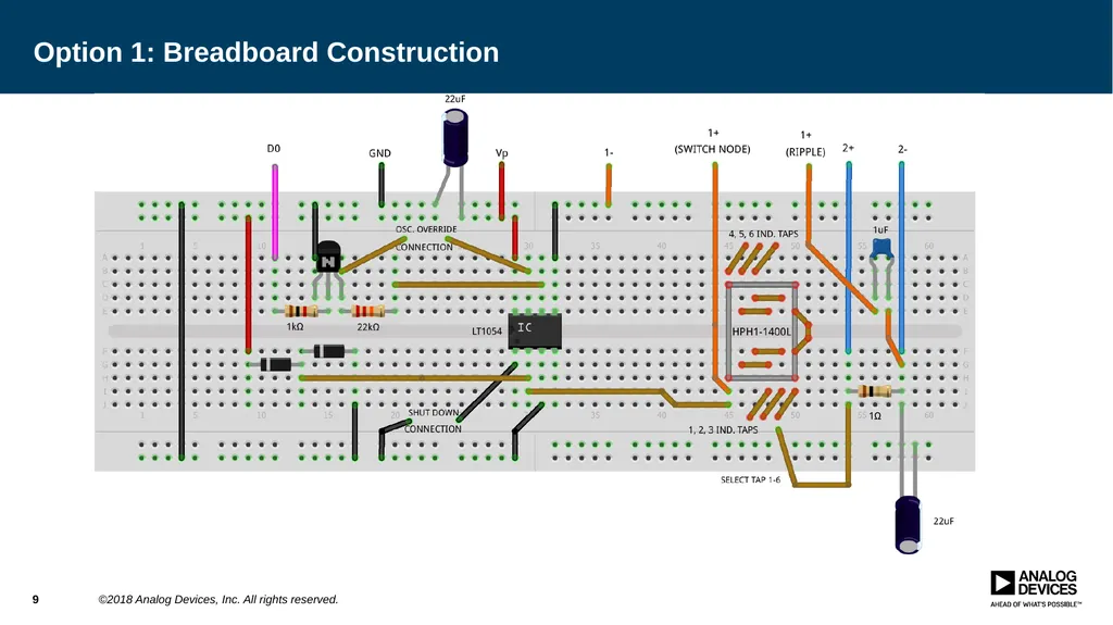
Option 1: Breadboard Construction 9 ©2018 Analog Devices, Inc. All rights reserved.<br>
10
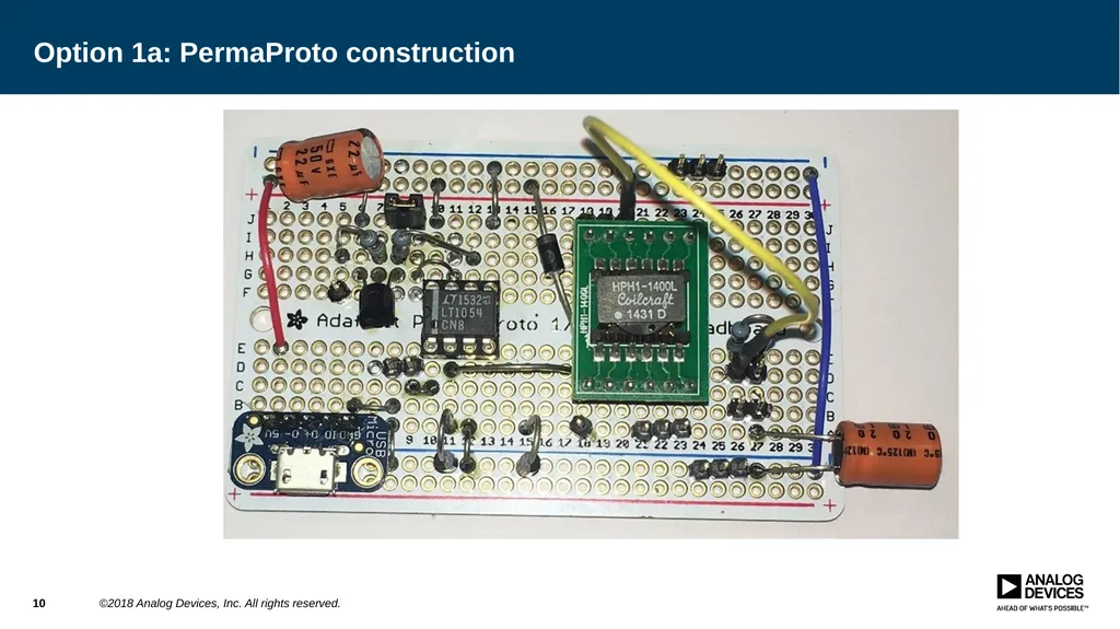
Option 1a: PermaProto construction 10 ©2018 Analog Devices, Inc. All rights reserved.<br>
11
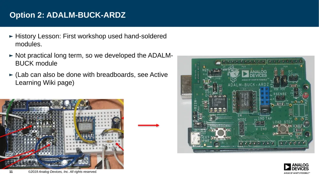
Option 2: ADALM-BUCK-ARDZ History Lesson: First workshop used hand-soldered modules.
Not practical long term, so we developed the ADALM-BUCK module
(Lab can also be done with breadboards, see Active Learning Wiki page) 11 ©2019 Analog Devices, Inc. All rights reserved.<br>
12
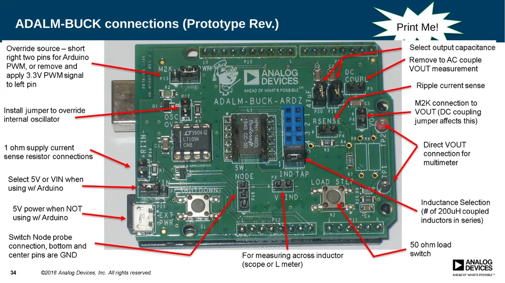
ADALM-BUCK connections (Prototype Rev.) 12 ©2018 Analog Devices, Inc. All rights reserved. Select output capacitance Inductance Selection: to pin 4,5,6,10,11,12) Short to use ext. pulse Switch Node probe conn. Ext. pulse source Ripple current sense 50 ohm load switch Print Me!<br>
13
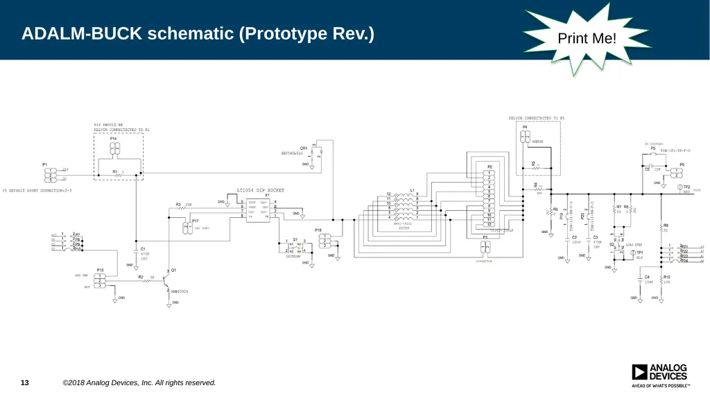
ADALM-BUCK schematic (Prototype Rev.) 13 ©2018 Analog Devices, Inc. All rights reserved. Print Me!<br>
14
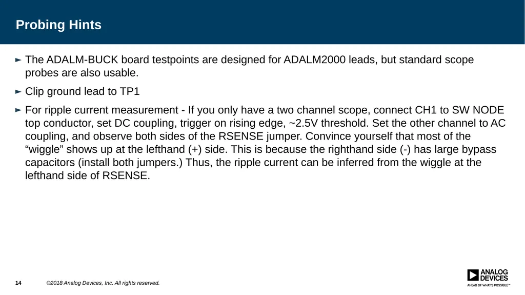
Probing Hints The ADALM-BUCK board testpoints are designed for ADALM2000 leads, but standard scope probes are also usable.
Clip ground lead to TP1
For ripple current measurement - If you only have a two channel scope, connect CH1 to SW NODE top conductor, set DC coupling, trigger on rising edge, ~2.5V threshold. Set the other channel to AC coupling, and observe both sides of the RSENSE jumper. Convince yourself that most of the “wiggle” shows up at the lefthand (+) side. This is because the righthand side (-) has large bypass capacitors (install both jumpers.) Thus, the ripple current can be inferred from the wiggle at the lefthand side of RSENSE. 14 ©2018 Analog Devices, Inc. All rights reserved.<br>
15
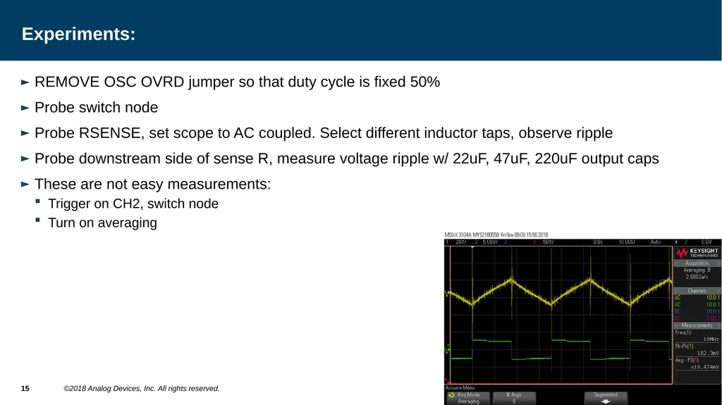
Experiments: REMOVE OSC OVRD jumper so that duty cycle is fixed 50%
Probe switch node
Probe RSENSE, set scope to AC coupled. Select different inductor taps, observe ripple
Probe downstream side of sense R, measure voltage ripple w/ 22uF, 47uF, 220uF output caps
These are not easy measurements:
Trigger on CH2, switch node
Turn on averaging 15 ©2018 Analog Devices, Inc. All rights reserved.<br>
16
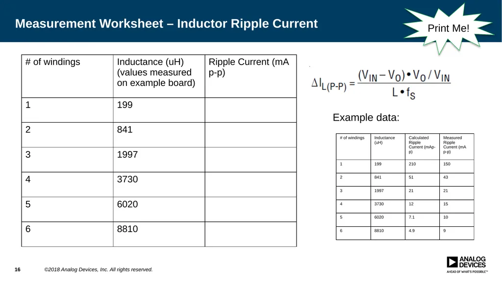
Measurement Worksheet – Inductor Ripple Current 16 ©2018 Analog Devices, Inc. All rights reserved. Example data: Print Me!<br>
17
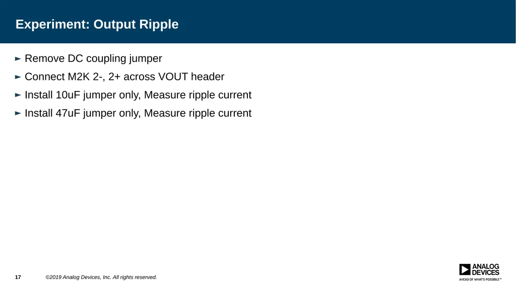
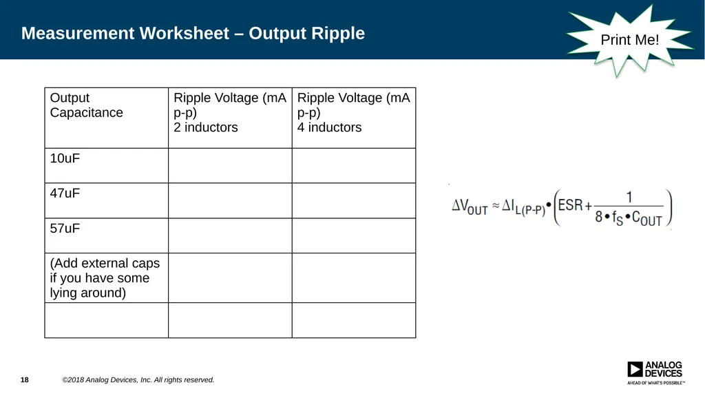
Experiment: Output Ripple Remove DC coupling jumper
Connect M2K 2-, 2+ across VOUT header
Install 10uF jumper only, Measure ripple current
Install 47uF jumper only, Measure ripple current 17 ©2019 Analog Devices, Inc. All rights reserved.<br>
18
Measurement Worksheet – Output Ripple 18 ©2018 Analog Devices, Inc. All rights reserved. Print Me!<br>
19
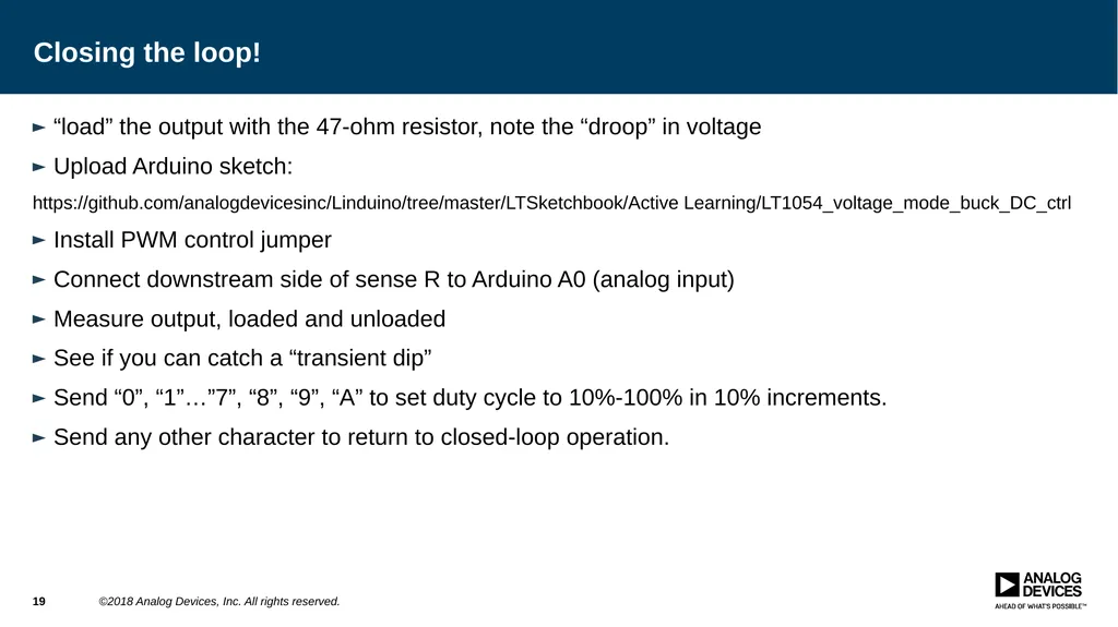
Closing the loop! “load” the output with the 47-ohm resistor, note the “droop” in voltage
Upload Arduino sketch:
https://github.com/analogdevicesinc/Linduino/tree/master/LTSketchbook/Active Learning/LT1054_voltage_mode_buck_DC_ctrl
Install PWM control jumper
Connect downstream side of sense R to Arduino A0 (analog input)
Measure output, loaded and unloaded
See if you can catch a “transient dip”
Send “0”, “1”…”7”, “8”, “9”, “A” to set duty cycle to 10%-100% in 10% increments.
Send any other character to return to closed-loop operation. 19 ©2018 Analog Devices, Inc. All rights reserved.<br>
20
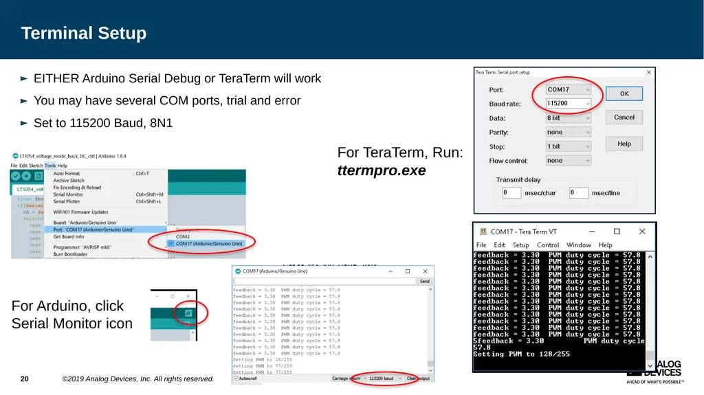
Terminal Setup EITHER Arduino Serial Debug or TeraTerm will work
You may have several COM ports, trial and error
Set to 115200 Baud, 8N1 20 ©2019 Analog Devices, Inc. All rights reserved. For TeraTerm, Run:
ttermpro.exe For Arduino, click Serial Monitor icon<br>
21
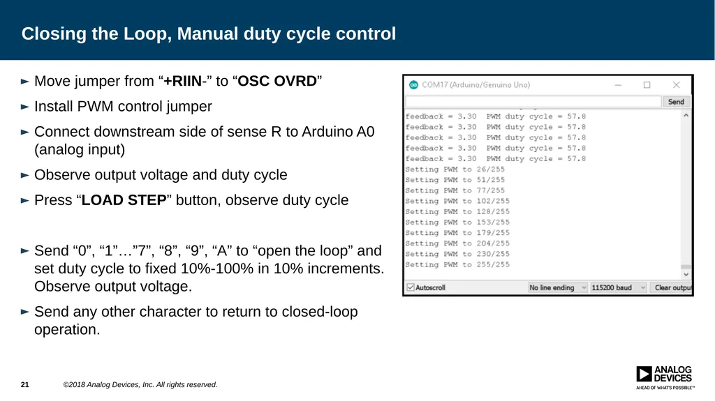
Closing the Loop, Manual duty cycle control Move jumper from “+RIIN-” to “OSC OVRD”
Install PWM control jumper
Connect downstream side of sense R to Arduino A0 (analog input)
Observe output voltage and duty cycle
Press “LOAD STEP” button, observe duty cycle
Send “0”, “1”…”7”, “8”, “9”, “A” to “open the loop” and set duty cycle to fixed 10%-100% in 10% increments. Observe output voltage.
Send any other character to return to closed-loop operation. 21 ©2018 Analog Devices, Inc. All rights reserved.<br>
22
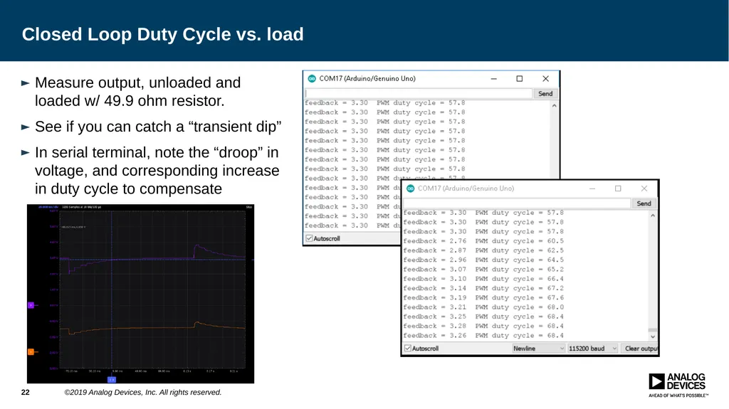
Closed Loop Duty Cycle vs. load Measure output, unloaded and loaded w/ 49.9 ohm resistor.
See if you can catch a “transient dip”
In serial terminal, note the “droop” in voltage, and corresponding increase in duty cycle to compensate 22 ©2019 Analog Devices, Inc. All rights reserved.<br>
23
Acknowledgements 23 ©2018 Analog Devices, Inc. All rights reserved.<br>
24
Thanks! 24 ©2018 Analog Devices, Inc. All rights reserved.<br>