
QUIZ 2 solutions 1 - Consider a file system with

Description: QUIZ 2 solutions 1 - Consider a file system with a graphical user interface, such as Macintoshs Finder, MicrosoftsWindows Explorer, or Linuxs KDE. The following objects were identified from a use case describing how to copy a file from a
Related Topics
Download Presentation
"QUIZ 2 solutions 1 - Consider a file system with" is the property of its rightful owner. Permission is granted to download and print the materials on this website for personal, non-commercial use only, and to display it on your personal computer provided you do not modify the materials and that you retain all copyright notices contained in the materials. By downloading content from our website, you accept the terms of this agreement.
Presentation Transcript
slide1. QUIZ 2 solutions<br>
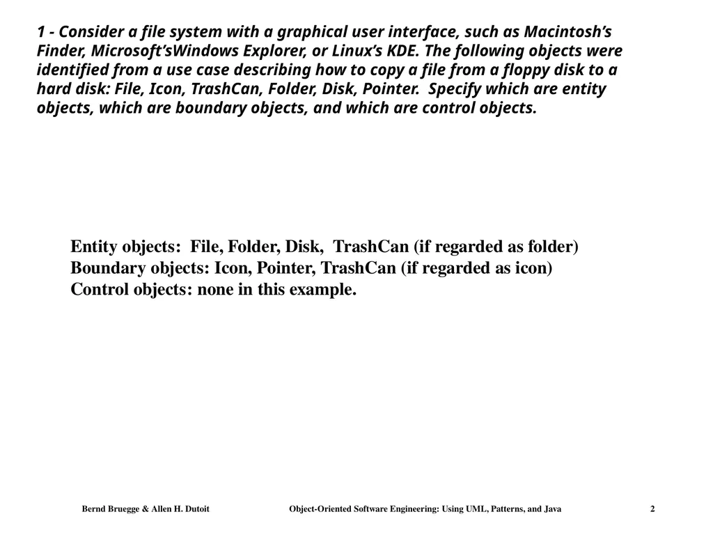
slide2. 1 - Consider a file system with a graphical user interface, such as Macintosh’s Finder, Microsoft’sWindows Explorer, or Linux’s KDE. The following objects were identified from a use case describing how to copy a file from a floppy disk to a hard disk: File, Icon, TrashCan, Folder, Disk, Pointer. Specify which are entity objects, which are boundary objects, and which are control objects. Entity objects: File, Folder, Disk, TrashCan (if regarded as folder)
Boundary objects: Icon, Pointer, TrashCan (if regarded as icon)
Control objects: none in this example.<br>
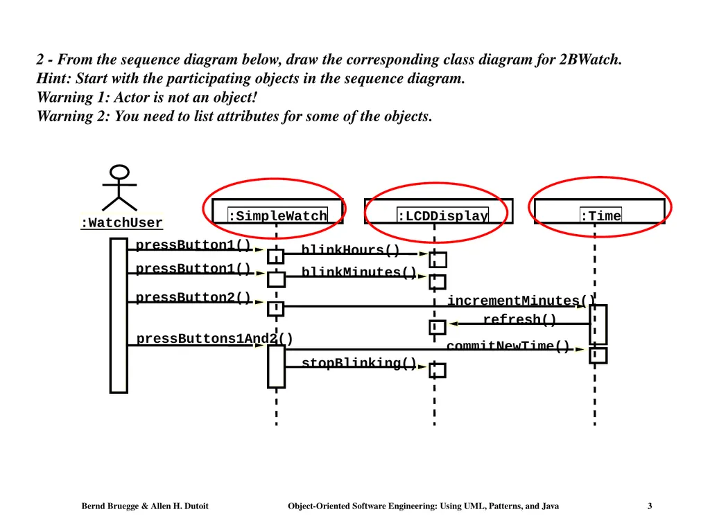
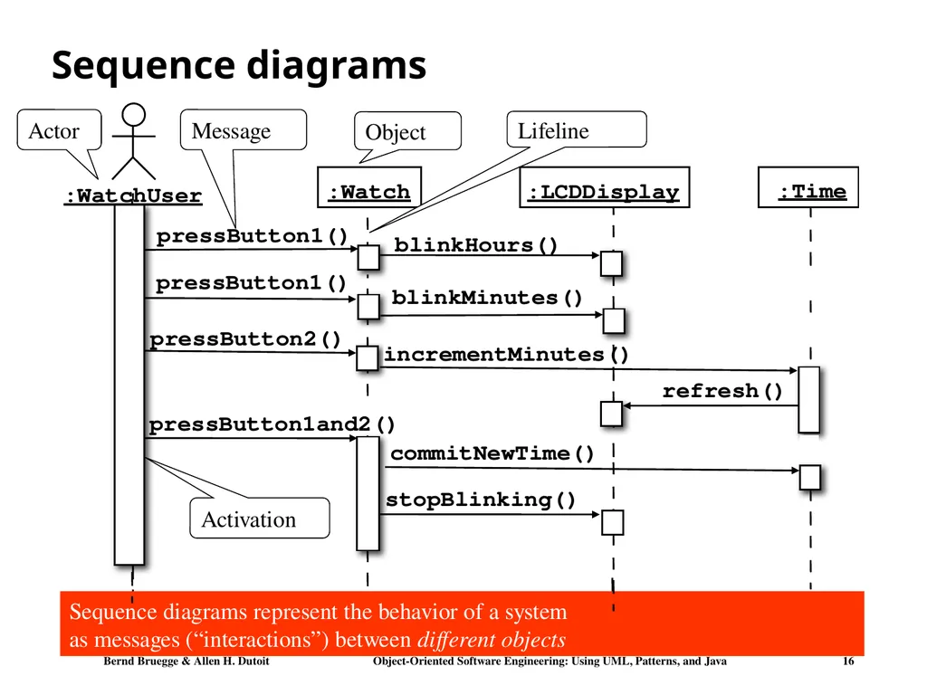
slide3. 2 - From the sequence diagram below, draw the corresponding class diagram for 2BWatch. Hint: Start with the participating objects in the sequence diagram.
Warning 1: Actor is not an object!
Warning 2: You need to list attributes for some of the objects.<br>
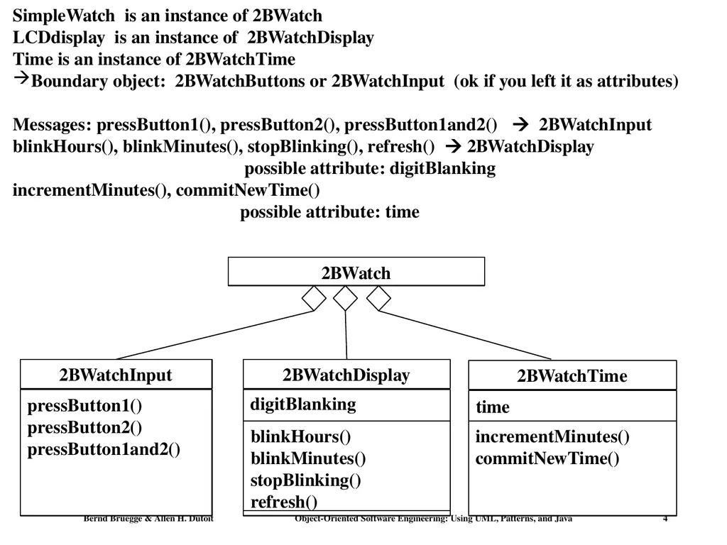
slide4. SimpleWatch is an instance of 2BWatch
LCDdisplay is an instance of 2BWatchDisplay
Time is an instance of 2BWatchTime
Boundary object: 2BWatchButtons or 2BWatchInput (ok if you left it as attributes)
Messages: pressButton1(), pressButton2(), pressButton1and2() 2BWatchInput
blinkHours(), blinkMinutes(), stopBlinking(), refresh() 2BWatchDisplay
possible attribute: digitBlanking
incrementMinutes(), commitNewTime()
possible attribute: time 2BWatch 2BWatchInput pressButton1()
pressButton2()
pressButton1and2() 2BWatchDisplay 2BWatchTime blinkHours()
blinkMinutes()
stopBlinking()
refresh() digitBlanking incrementMinutes()
commitNewTime() time<br>
slide5. Midterm: Chapters 1-5<br>
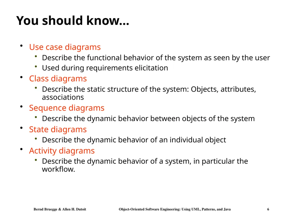
slide6. You should know… Use case diagrams
Describe the functional behavior of the system as seen by the user
Used during requirements elicitation
Class diagrams
Describe the static structure of the system: Objects, attributes, associations
Sequence diagrams
Describe the dynamic behavior between objects of the system
State diagrams
Describe the dynamic behavior of an individual object
Activity diagrams
Describe the dynamic behavior of a system, in particular the workflow.<br>
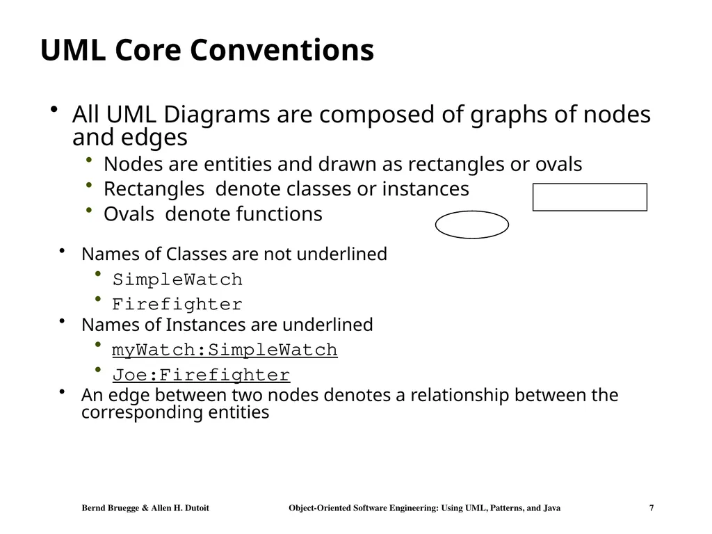
slide7. UML Core Conventions All UML Diagrams are composed of graphs of nodes and edges
Nodes are entities and drawn as rectangles or ovals
Rectangles denote classes or instances
Ovals denote functions Names of Classes are not underlined
SimpleWatch
Firefighter
Names of Instances are underlined
myWatch:SimpleWatch
Joe:Firefighter
An edge between two nodes denotes a relationship between the corresponding entities<br>
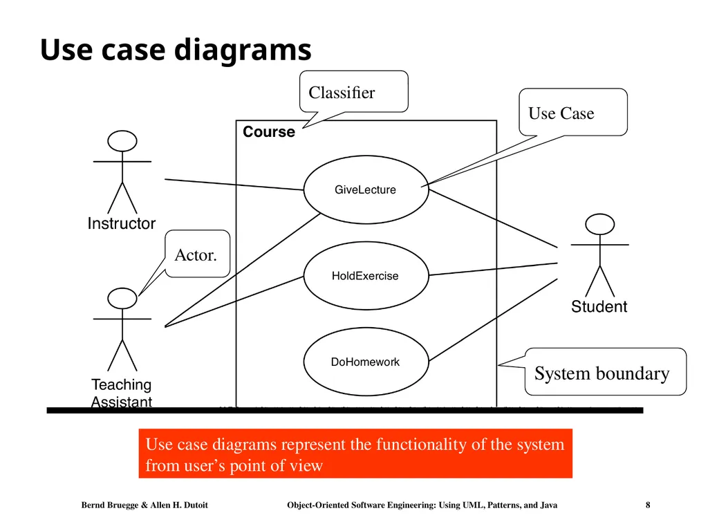
slide8. Use case diagrams Use case diagrams represent the functionality of the system
from user’s point of view Actor. Use Case System boundary Classifier<br>
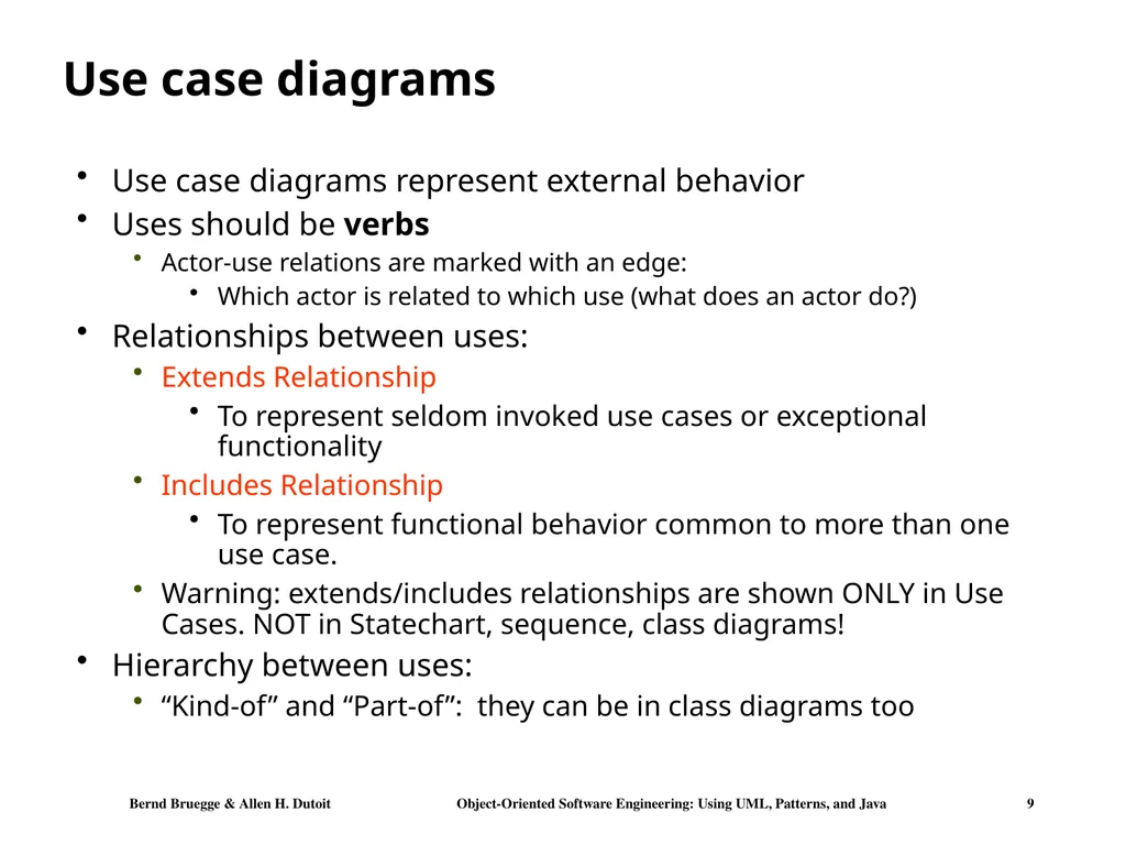
slide9. Use case diagrams Use case diagrams represent external behavior
Uses should be verbs
Actor-use relations are marked with an edge:
Which actor is related to which use (what does an actor do?)
Relationships between uses:
Extends Relationship
To represent seldom invoked use cases or exceptional functionality
Includes Relationship
To represent functional behavior common to more than one use case.
Warning: extends/includes relationships are shown ONLY in Use Cases. NOT in Statechart, sequence, class diagrams!
Hierarchy between uses:
“Kind-of” and “Part-of”: they can be in class diagrams too<br>
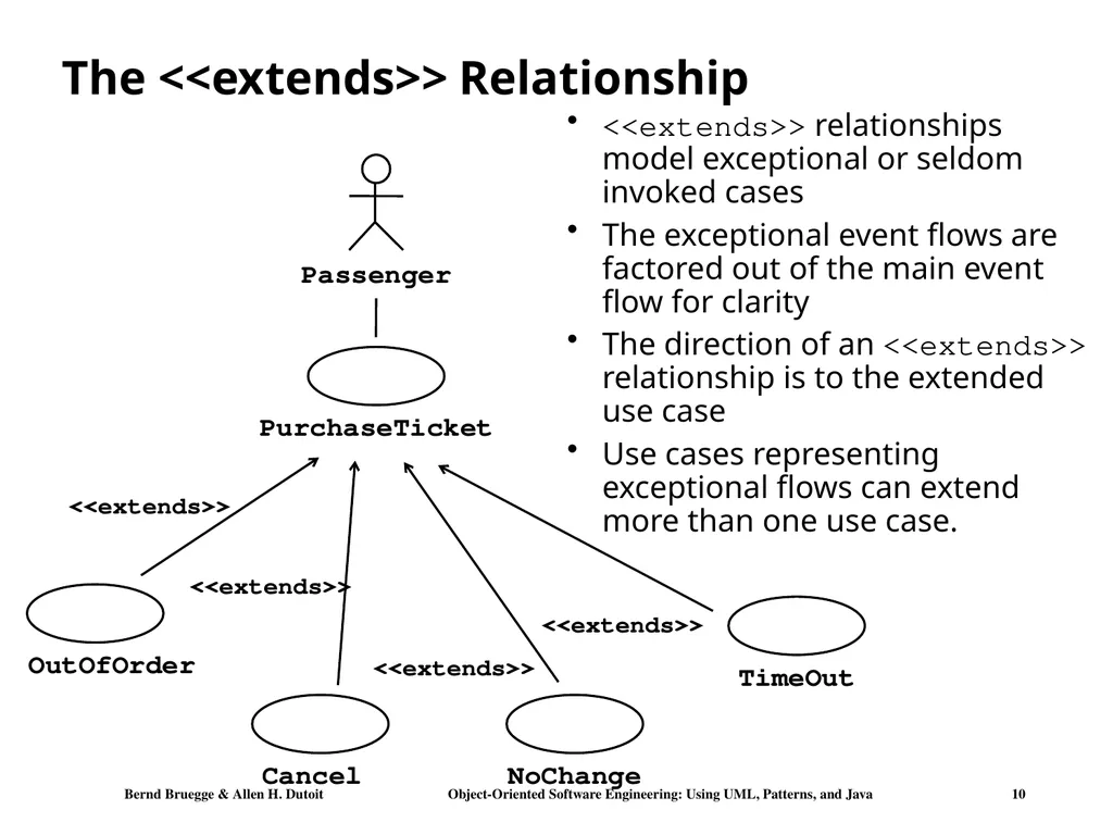
slide10. The <<extends>> Relationship <<extends>> relationships model exceptional or seldom invoked cases
The exceptional event flows are factored out of the main event flow for clarity
The direction of an <<extends>> relationship is to the extended use case
Use cases representing exceptional flows can extend more than one use case.<br>
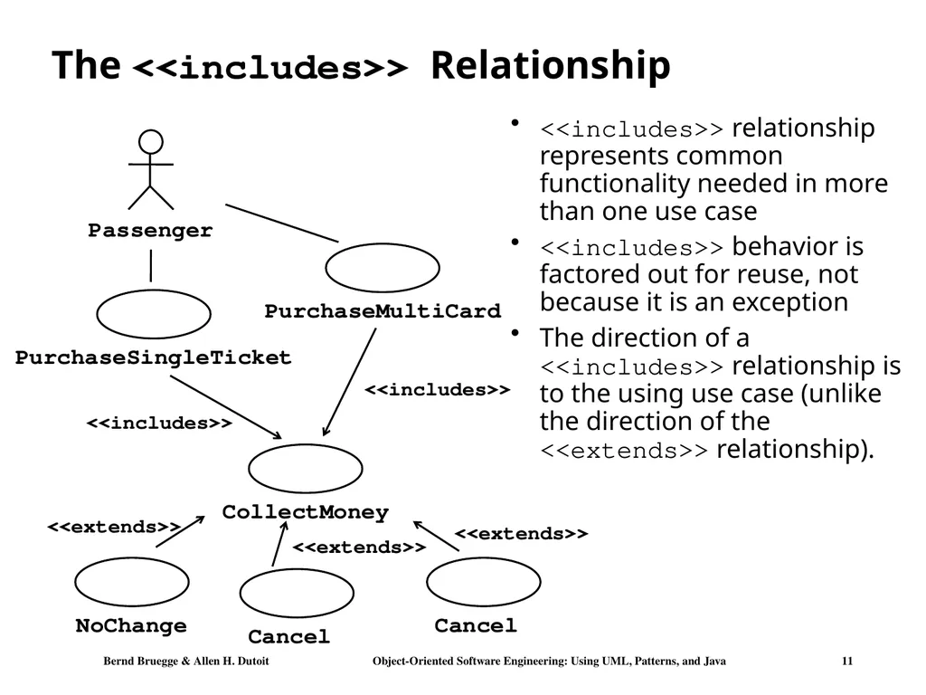
slide11. The <<includes>> Relationship <<includes>> relationship represents common functionality needed in more than one use case
<<includes>> behavior is factored out for reuse, not because it is an exception
The direction of a <<includes>> relationship is to the using use case (unlike the direction of the <<extends>> relationship).<br>
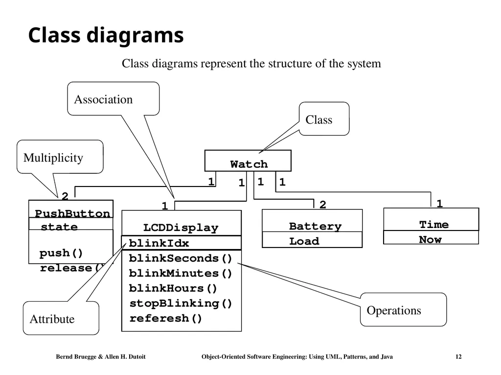
slide12. Class diagrams 1 2 push() release() 1 Watch Operations state PushButton Attribute Class diagrams represent the structure of the system Class Association Multiplicity<br>
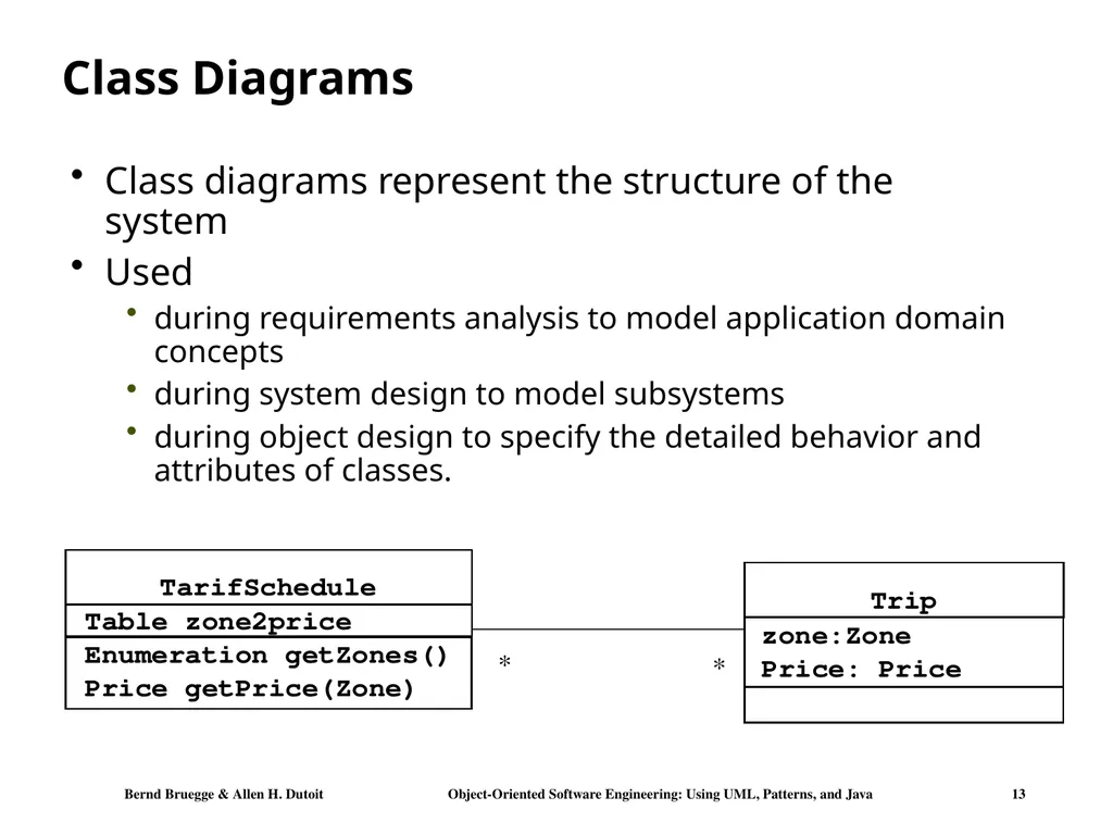
slide13. Class Diagrams Class diagrams represent the structure of the system
Used
during requirements analysis to model application domain concepts
during system design to model subsystems
during object design to specify the detailed behavior and attributes of classes.<br>
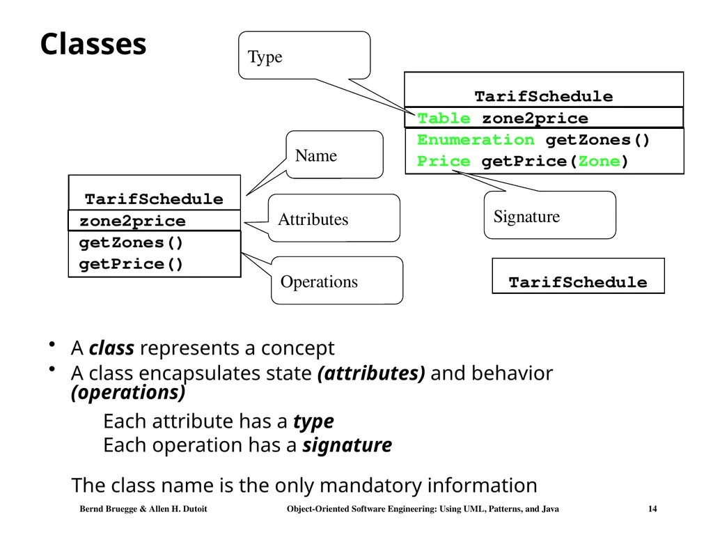
slide14. Classes A class represents a concept
A class encapsulates state (attributes) and behavior (operations) Signature The class name is the only mandatory information Each attribute has a type
Each operation has a signature Type<br>
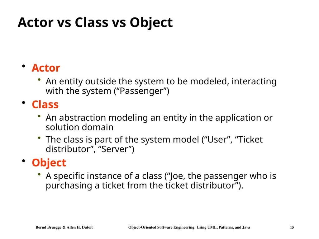
slide15. Actor vs Class vs Object Actor
An entity outside the system to be modeled, interacting with the system (“Passenger”)
Class
An abstraction modeling an entity in the application or solution domain
The class is part of the system model (“User”, “Ticket distributor”, “Server”)
Object
A specific instance of a class (“Joe, the passenger who is purchasing a ticket from the ticket distributor”).<br>
slide16. Message Sequence diagrams :Time Object Activation Sequence diagrams represent the behavior of a system
as messages (“interactions”) between different objects Actor Lifeline<br>
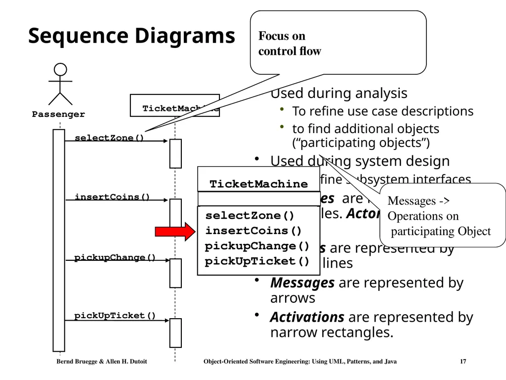
slide17. Sequence Diagrams Used during analysis
To refine use case descriptions
to find additional objects (“participating objects”)
Used during system design
to refine subsystem interfaces
Instances are represented by rectangles. Actors by sticky figures
Lifelines are represented by dashed lines
Messages are represented by arrows
Activations are represented by narrow rectangles. Focus on
control flow Messages ->
Operations on
participating Object<br>
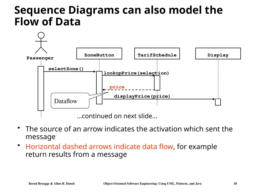
slide18. Sequence Diagrams can also model the Flow of Data The source of an arrow indicates the activation which sent the message
Horizontal dashed arrows indicate data flow, for example return results from a message Dataflow …continued on next slide...<br>
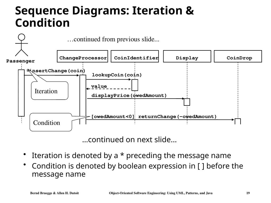
slide19. Sequence Diagrams: Iteration & Condition Iteration is denoted by a * preceding the message name
Condition is denoted by boolean expression in [ ] before the message name ChangeProcessor Iteration Condition …continued on next slide... …continued from previous slide... *<br>
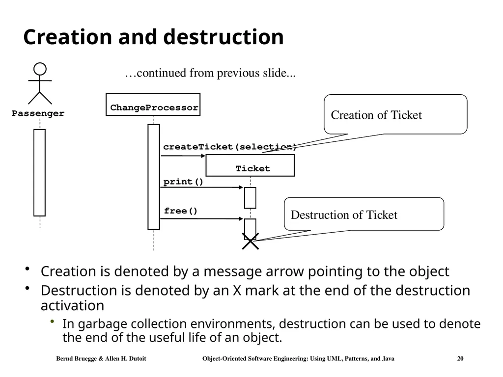
slide20. Creation and destruction Creation is denoted by a message arrow pointing to the object
Destruction is denoted by an X mark at the end of the destruction activation
In garbage collection environments, destruction can be used to denote the end of the useful life of an object. ChangeProcessor …continued from previous slide... Creation of Ticket Destruction of Ticket<br>
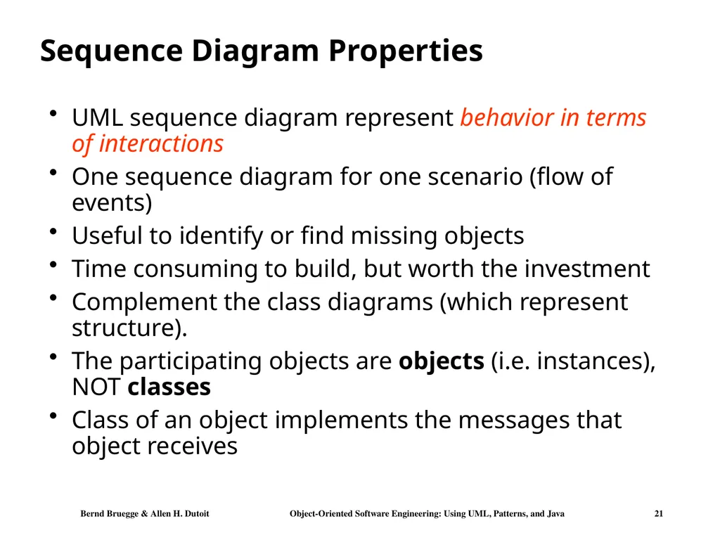
slide21. Sequence Diagram Properties UML sequence diagram represent behavior in terms of interactions
One sequence diagram for one scenario (flow of events)
Useful to identify or find missing objects
Time consuming to build, but worth the investment
Complement the class diagrams (which represent structure).
The participating objects are objects (i.e. instances), NOT classes
Class of an object implements the messages that object receives<br>
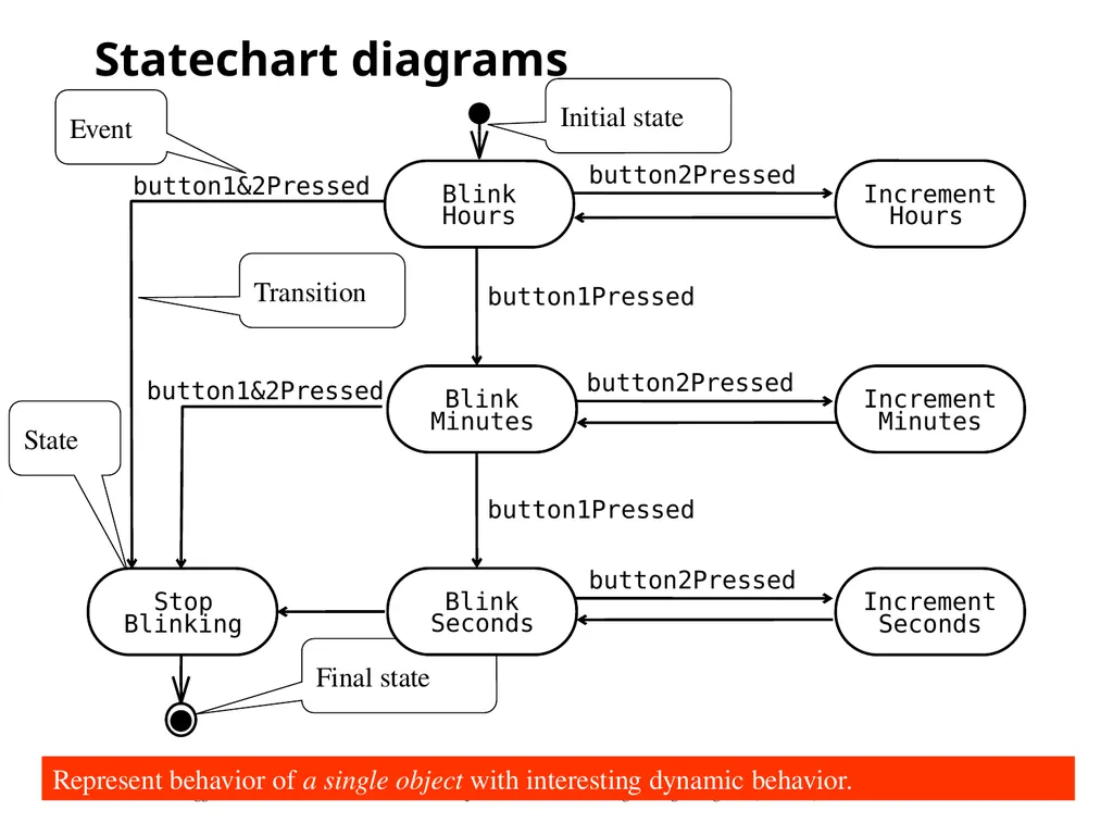
slide22. Statechart diagrams State Initial state Final state Transition Event Represent behavior of a single object with interesting dynamic behavior.<br>
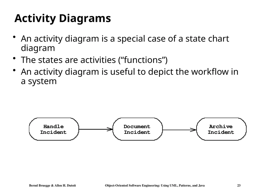
slide23. Activity Diagrams An activity diagram is a special case of a state chart diagram
The states are activities (“functions”)
An activity diagram is useful to depict the workflow in a system<br>
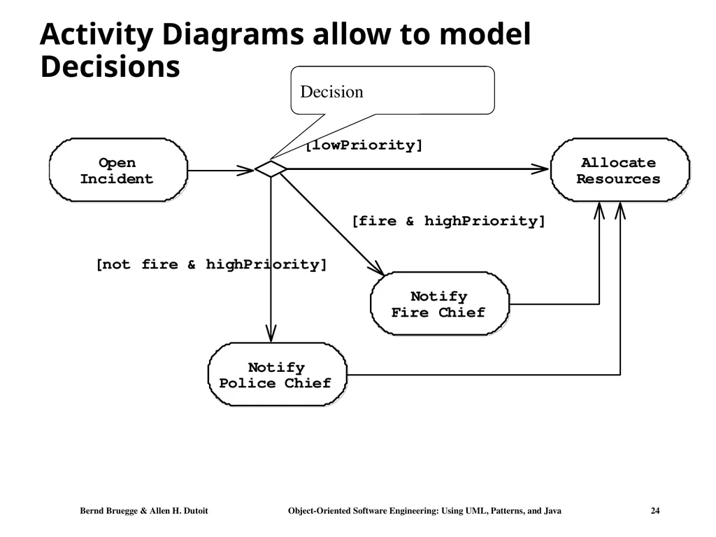
slide24. Activity Diagrams allow to model Decisions Decision<br>
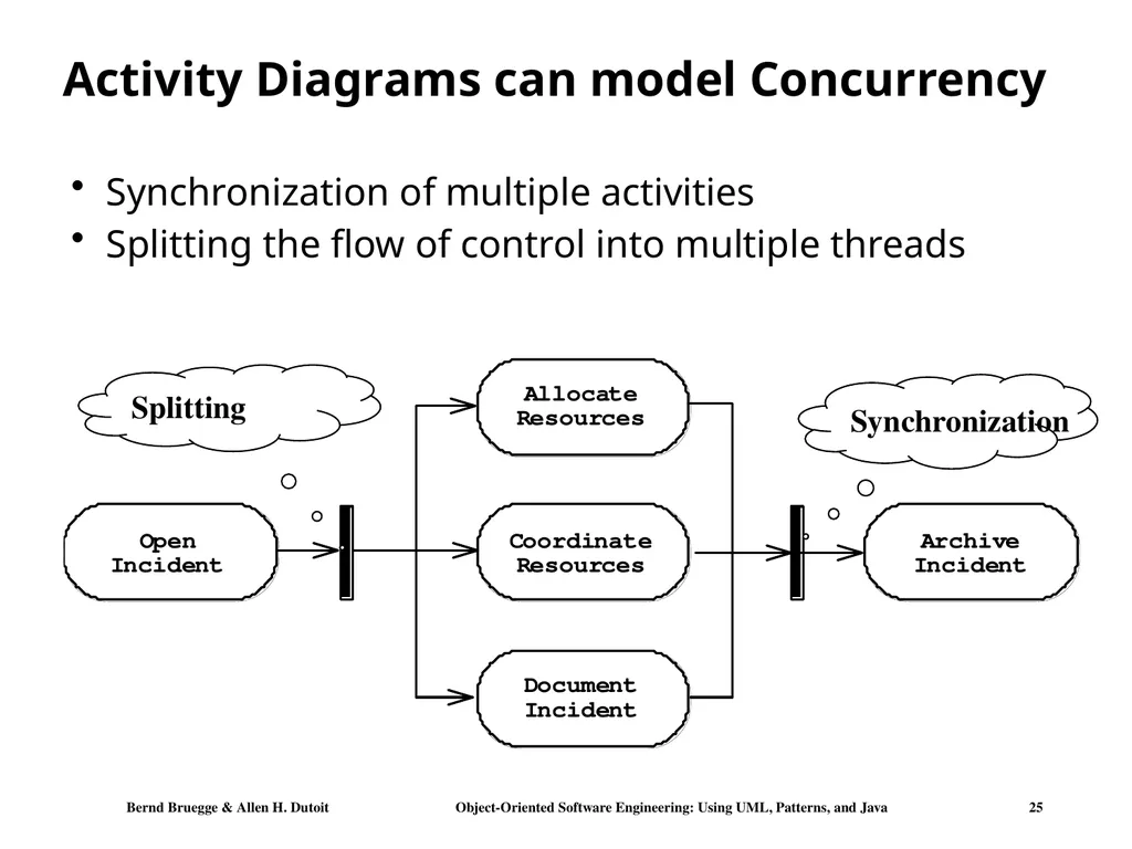
slide25. Activity Diagrams can model Concurrency Synchronization of multiple activities
Splitting the flow of control into multiple threads Synchronization Splitting<br>
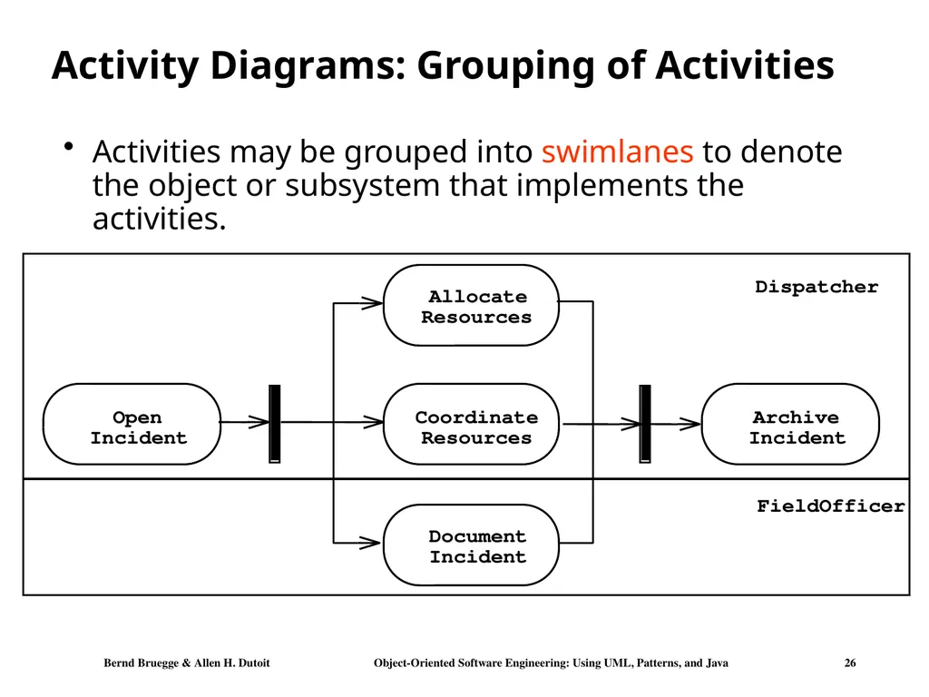
slide26. Activity Diagrams: Grouping of Activities Activities may be grouped into swimlanes to denote the object or subsystem that implements the activities. Open Incident Allocate Resources Coordinate Resources Document Incident Archive Incident Dispatcher FieldOfficer<br>
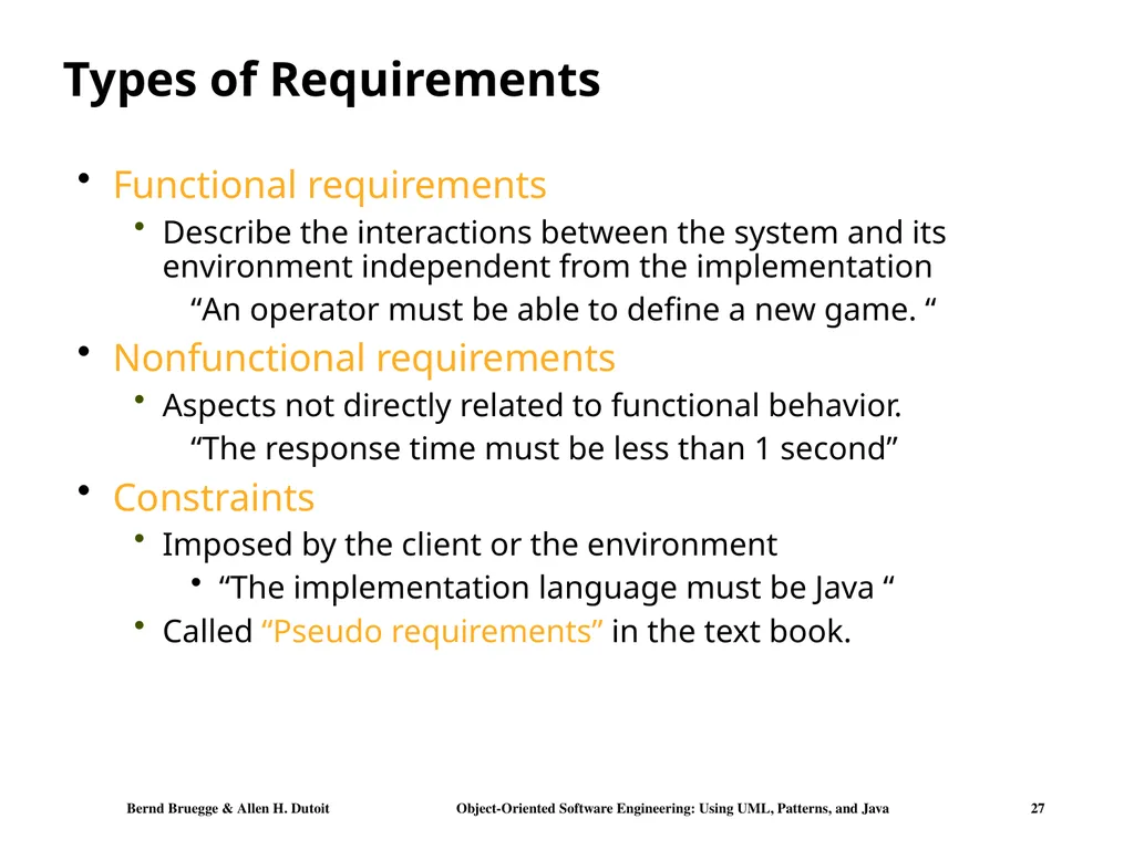
slide27. Types of Requirements Functional requirements
Describe the interactions between the system and its environment independent from the implementation
“An operator must be able to define a new game. “
Nonfunctional requirements
Aspects not directly related to functional behavior.
“The response time must be less than 1 second”
Constraints
Imposed by the client or the environment
“The implementation language must be Java “
Called “Pseudo requirements” in the text book.<br>
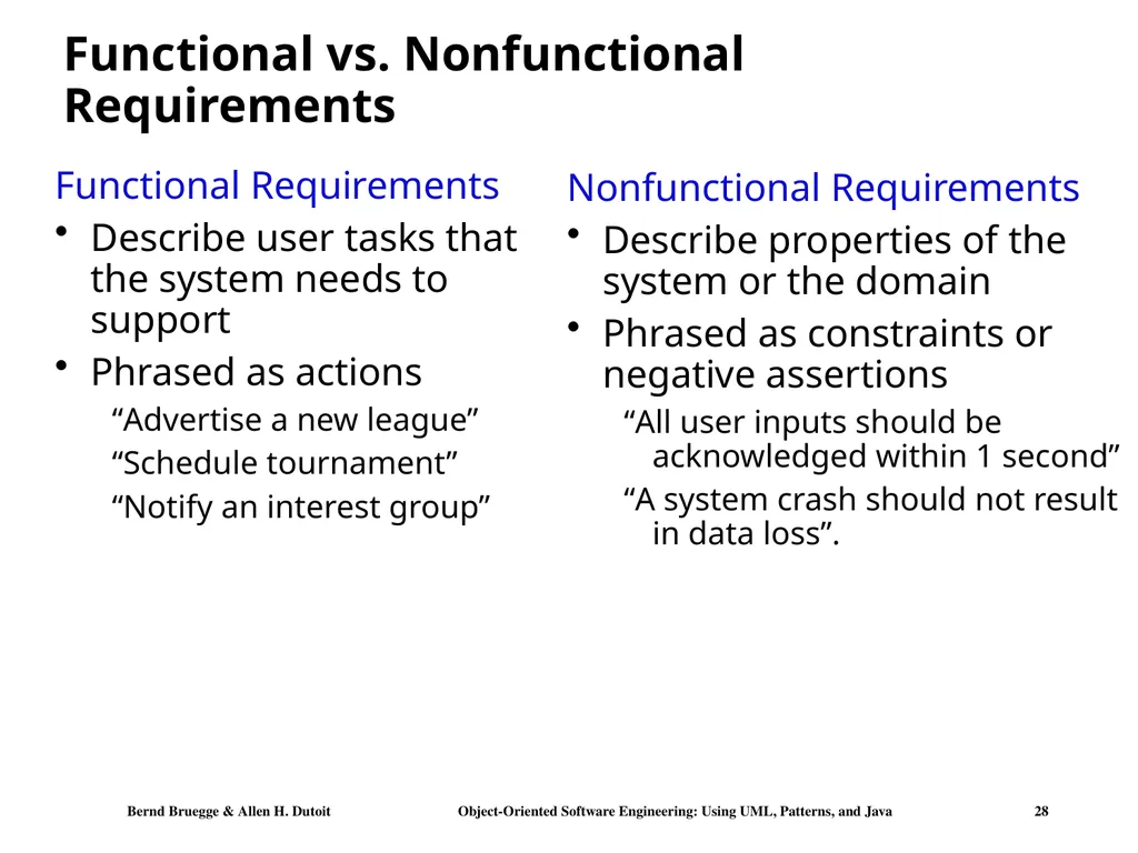
slide28. Functional vs. Nonfunctional Requirements Functional Requirements
Describe user tasks that the system needs to support
Phrased as actions
“Advertise a new league”
“Schedule tournament”
“Notify an interest group” Nonfunctional Requirements
Describe properties of the system or the domain
Phrased as constraints or negative assertions
“All user inputs should be acknowledged within 1 second”
“A system crash should not result in data loss”.<br>
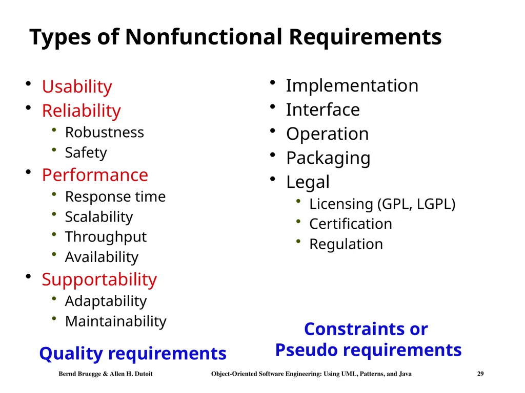
slide29. Types of Nonfunctional Requirements Usability
Reliability
Robustness
Safety
Performance
Response time
Scalability
Throughput
Availability
Supportability
Adaptability
Maintainability Implementation
Interface
Operation
Packaging
Legal
Licensing (GPL, LGPL)
Certification
Regulation Quality requirements Constraints or Pseudo requirements<br>
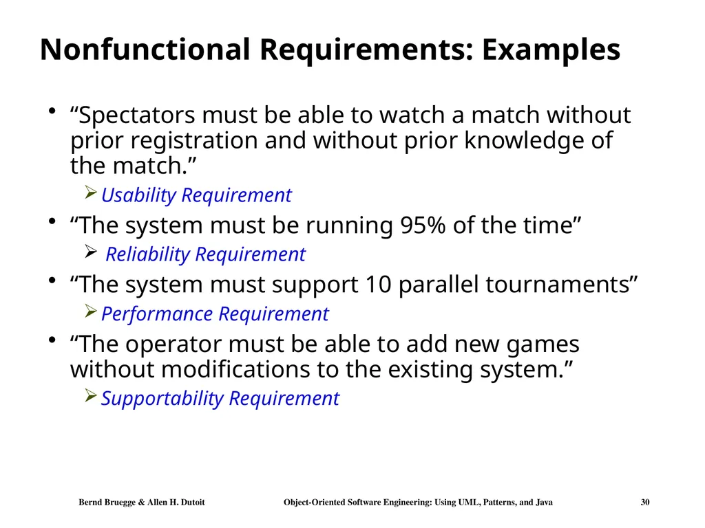
slide30. Nonfunctional Requirements: Examples “Spectators must be able to watch a match without prior registration and without prior knowledge of the match.”
Usability Requirement
“The system must be running 95% of the time”
Reliability Requirement
“The system must support 10 parallel tournaments”
Performance Requirement
“The operator must be able to add new games without modifications to the existing system.”
Supportability Requirement<br>
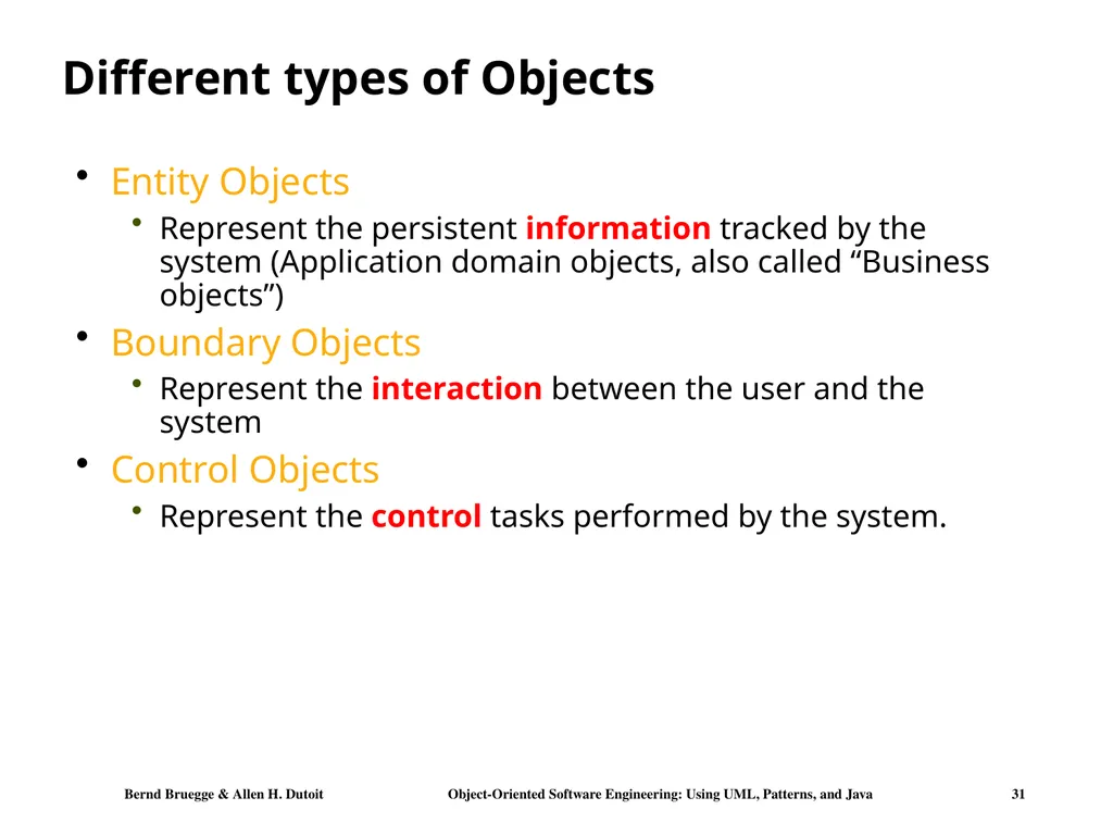
slide31. Different types of Objects Entity Objects
Represent the persistent information tracked by the system (Application domain objects, also called “Business objects”)
Boundary Objects
Represent the interaction between the user and the system
Control Objects
Represent the control tasks performed by the system.<br>
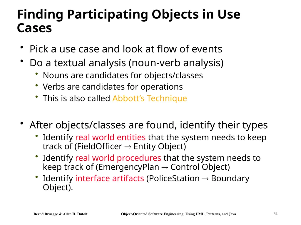
slide32. Finding Participating Objects in Use Cases Pick a use case and look at flow of events
Do a textual analysis (noun-verb analysis)
Nouns are candidates for objects/classes
Verbs are candidates for operations
This is also called Abbott’s Technique
After objects/classes are found, identify their types
Identify real world entities that the system needs to keep track of (FieldOfficer Entity Object)
Identify real world procedures that the system needs to keep track of (EmergencyPlan Control Object)
Identify interface artifacts (PoliceStation Boundary Object).<br>
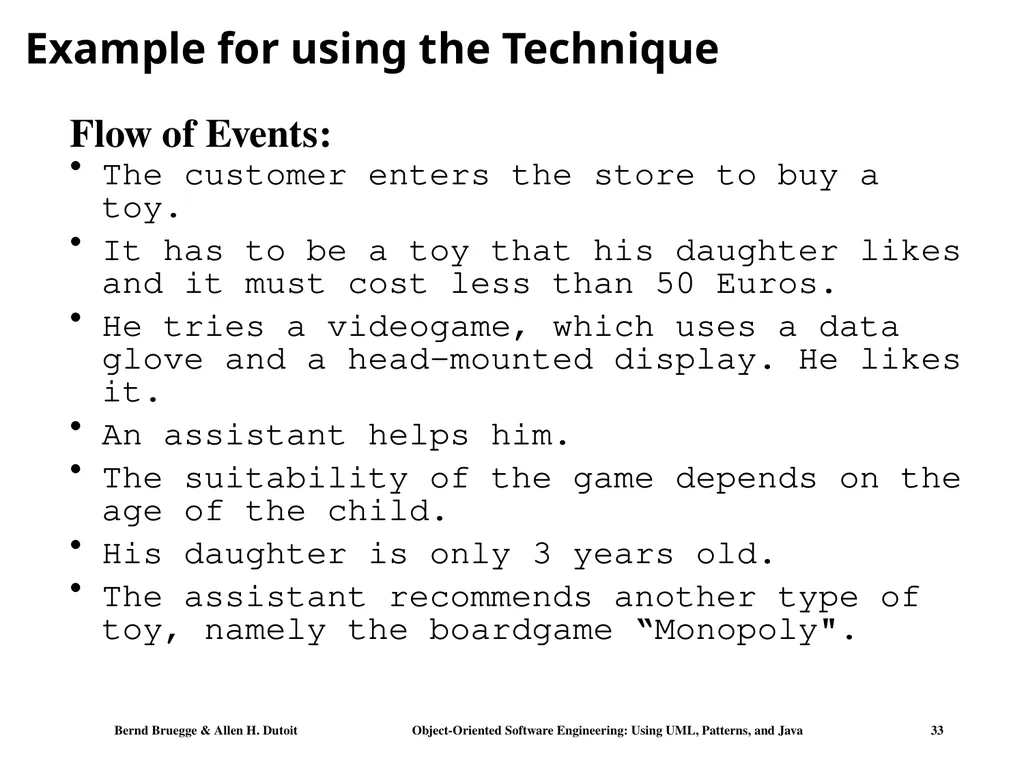
slide33. Example for using the Technique The customer enters the store to buy a toy.
It has to be a toy that his daughter likes and it must cost less than 50 Euros.
He tries a videogame, which uses a data glove and a head-mounted display. He likes it.
An assistant helps him.
The suitability of the game depends on the age of the child.
His daughter is only 3 years old.
The assistant recommends another type of toy, namely the boardgame “Monopoly". Flow of Events:<br>
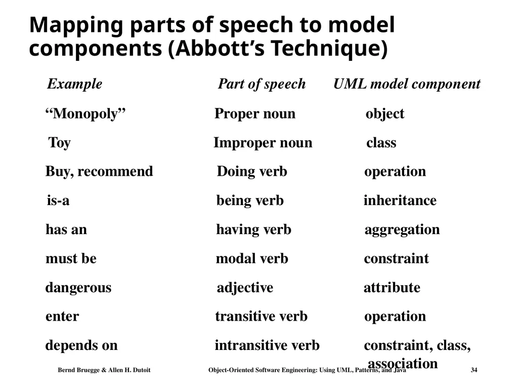
slide34. Mapping parts of speech to model components (Abbott’s Technique)<br>
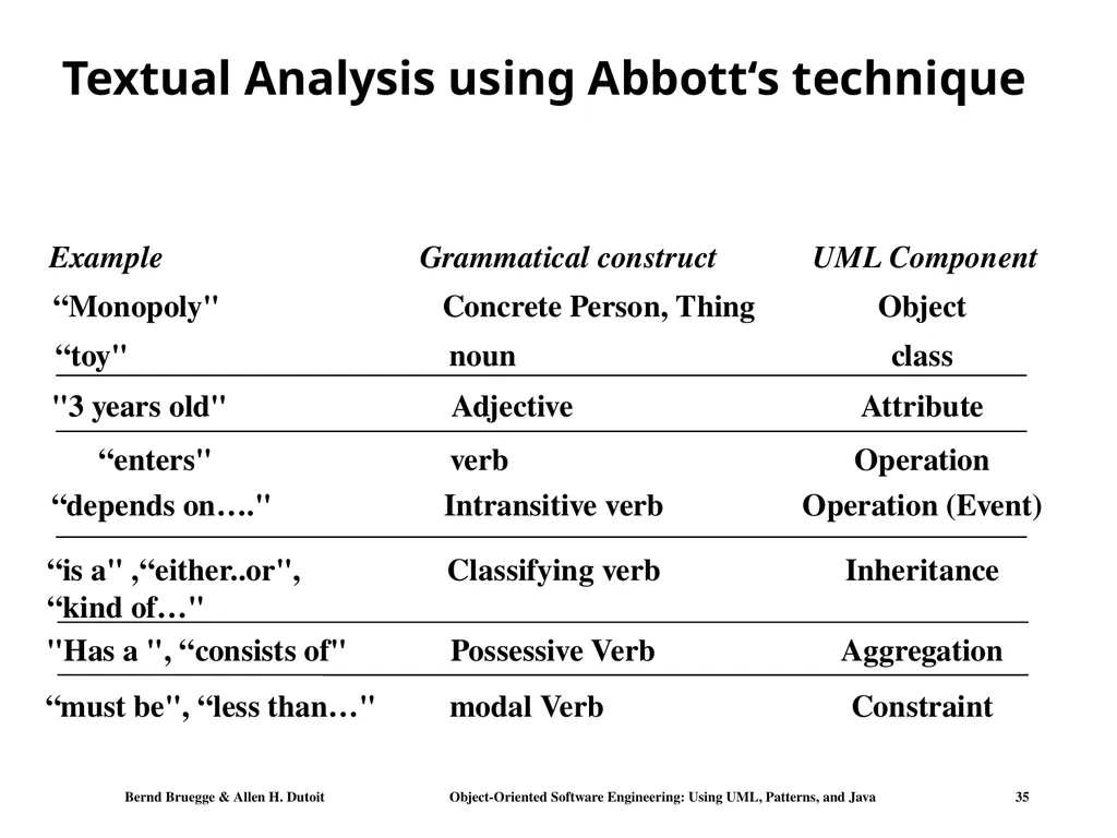
slide35. Grammatical construct UML Component Concrete Person, Thing Object noun class verb Operation Classifying verb Inheritance Possessive Verb Aggregation modal Verb Constraint Adjective Attribute Intransitive verb Operation (Event) Textual Analysis using Abbott‘s technique Example “Monopoly" “toy" “enters" “is a" ,“either..or",
“kind of…" "Has a ", “consists of" “must be", “less than…" "3 years old" “depends on…."<br>
slide36. The customer enters the store to buy a toy. It has to be a toy that his daughter likes and it must cost less than 50 Euro. He tries a videogame, which uses a data glove and a head-mounted display. He likes it. Generating a Class Diagram from Flow of Events An assistant helps him. The suitability of the game depends on the age of the child. His daughter is only 3 years old. The assistant recommends another type of toy, namely a boardgame. The customer buy the game and leaves the store Customer Flow of events:<br>
slide37. Chapter 7 System Design: Addressing Design Goals<br>
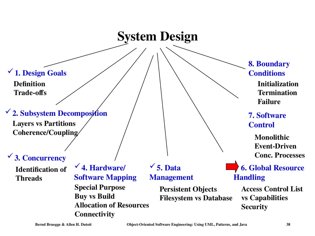
slide38. System Design 4. Hardware/
Software Mapping<br>
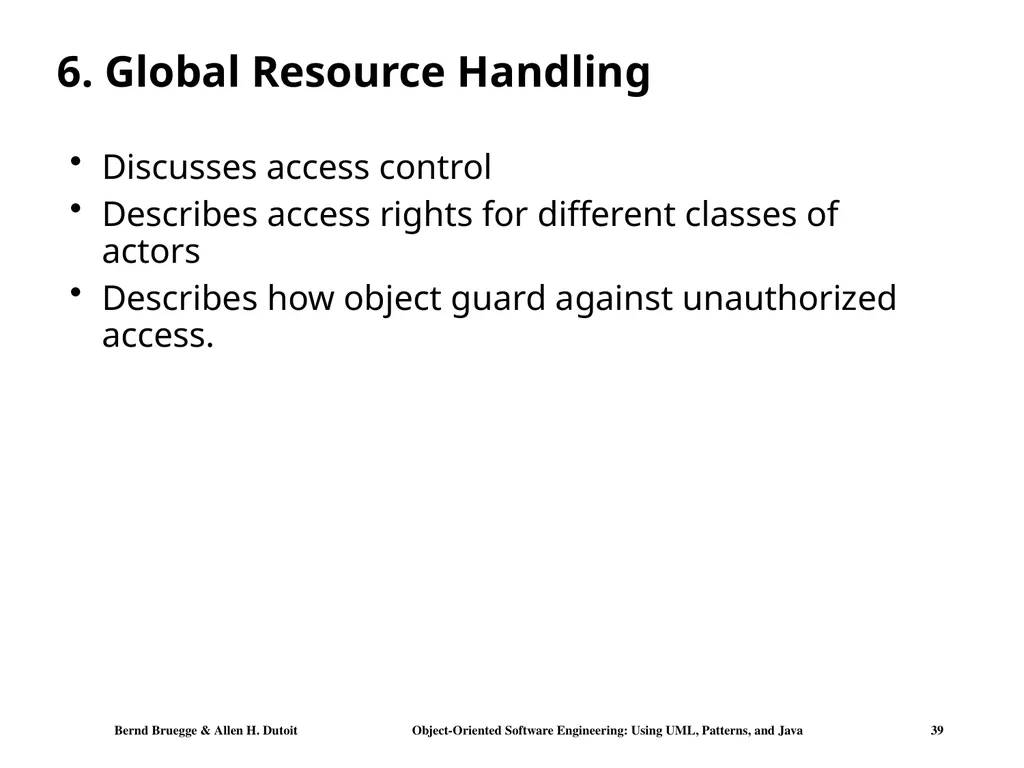
slide39. 6. Global Resource Handling Discusses access control
Describes access rights for different classes of actors
Describes how object guard against unauthorized access.<br>
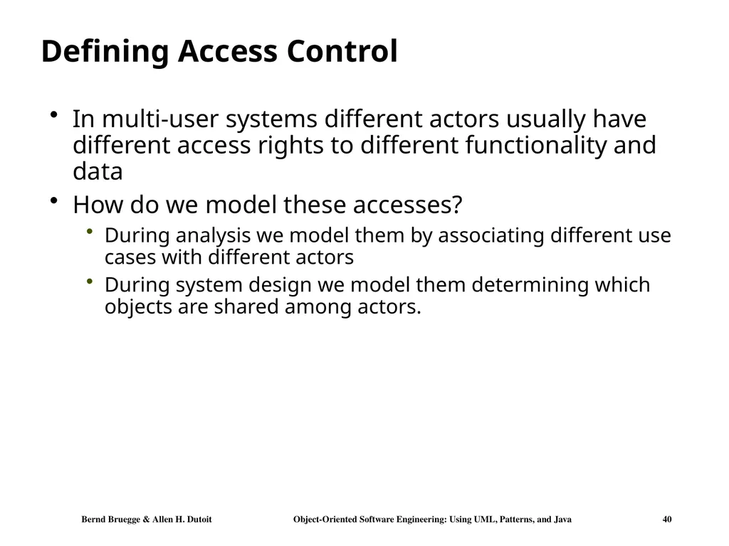
slide40. Defining Access Control In multi-user systems different actors usually have different access rights to different functionality and data
How do we model these accesses?
During analysis we model them by associating different use cases with different actors
During system design we model them determining which objects are shared among actors.<br>
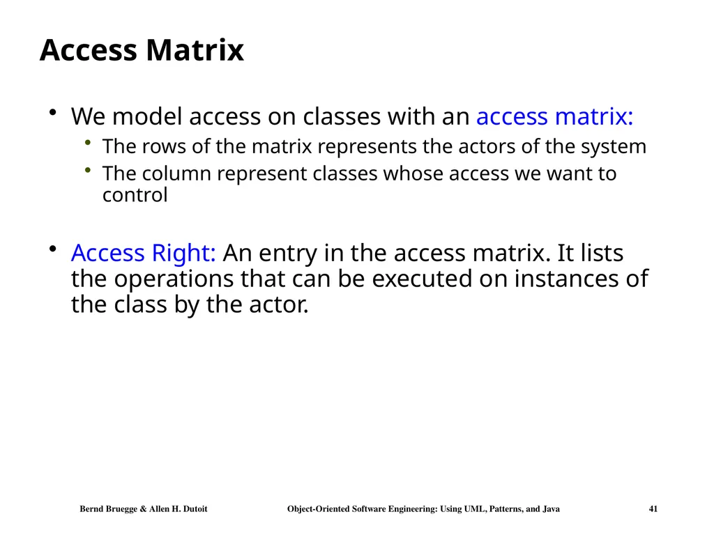
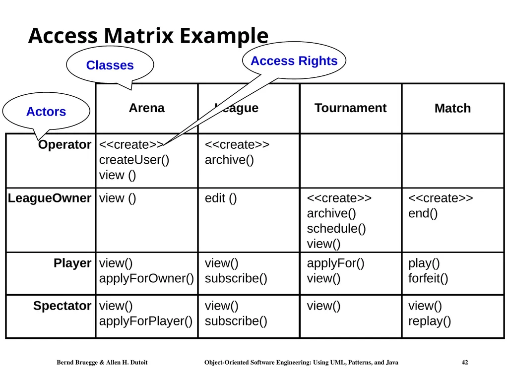
slide41. Access Matrix We model access on classes with an access matrix:
The rows of the matrix represents the actors of the system
The column represent classes whose access we want to control
Access Right: An entry in the access matrix. It lists the operations that can be executed on instances of the class by the actor.<br>
slide42. Access Matrix Example Arena League Operator LeagueOwner Player Spectator Tournament <<create>> archive() schedule() view() applyFor() view() view() <<create>> createUser() view () view () view() applyForPlayer() view() applyForOwner() <<create>> archive() view() subscribe() view() subscribe() edit () Match <<create>> end() play() forfeit() view() replay() Actors Classes Access Rights<br>
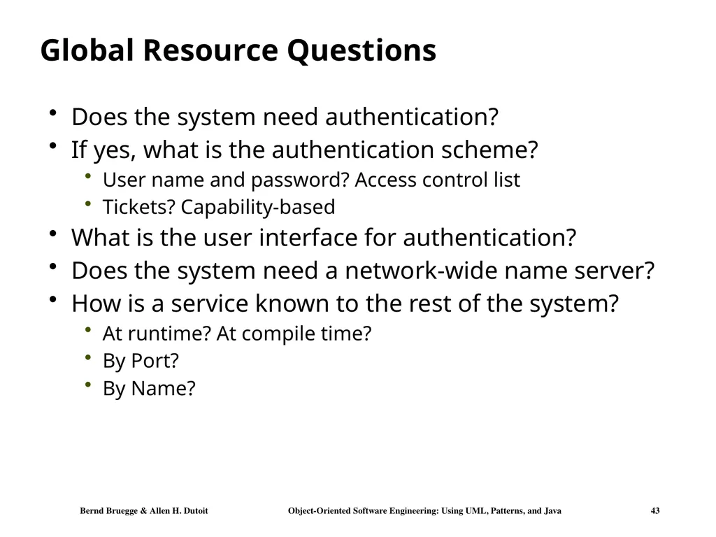
slide43. Global Resource Questions Does the system need authentication?
If yes, what is the authentication scheme?
User name and password? Access control list
Tickets? Capability-based
What is the user interface for authentication?
Does the system need a network-wide name server?
How is a service known to the rest of the system?
At runtime? At compile time?
By Port?
By Name?<br>
slide44. System Design 4. Hardware/
Software Mapping<br>
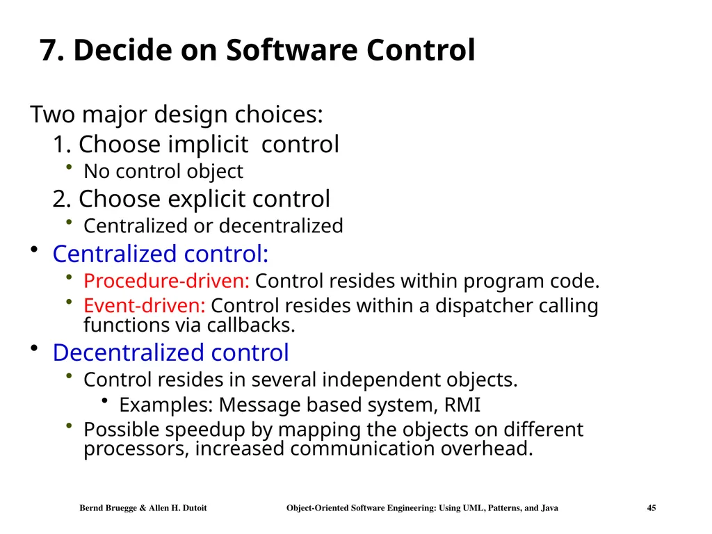
slide45. 7. Decide on Software Control Two major design choices:
1. Choose implicit control
No control object
2. Choose explicit control
Centralized or decentralized
Centralized control:
Procedure-driven: Control resides within program code.
Event-driven: Control resides within a dispatcher calling functions via callbacks.
Decentralized control
Control resides in several independent objects.
Examples: Message based system, RMI
Possible speedup by mapping the objects on different processors, increased communication overhead.<br>
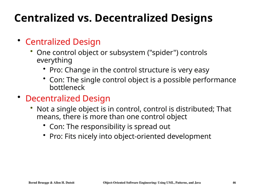
slide46. Centralized vs. Decentralized Designs Centralized Design
One control object or subsystem ("spider") controls everything
Pro: Change in the control structure is very easy
Con: The single control object is a possible performance bottleneck
Decentralized Design
Not a single object is in control, control is distributed; That means, there is more than one control object
Con: The responsibility is spread out
Pro: Fits nicely into object-oriented development<br>
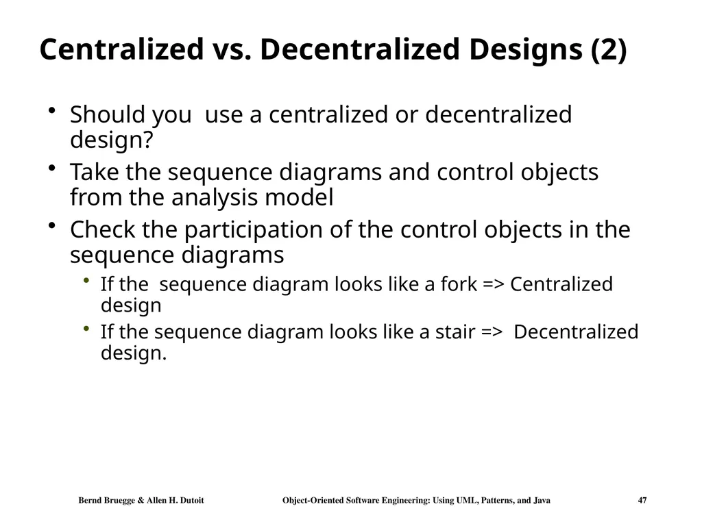
slide47. Centralized vs. Decentralized Designs (2) Should you use a centralized or decentralized design?
Take the sequence diagrams and control objects from the analysis model
Check the participation of the control objects in the sequence diagrams
If the sequence diagram looks like a fork => Centralized design
If the sequence diagram looks like a stair => Decentralized design.<br>
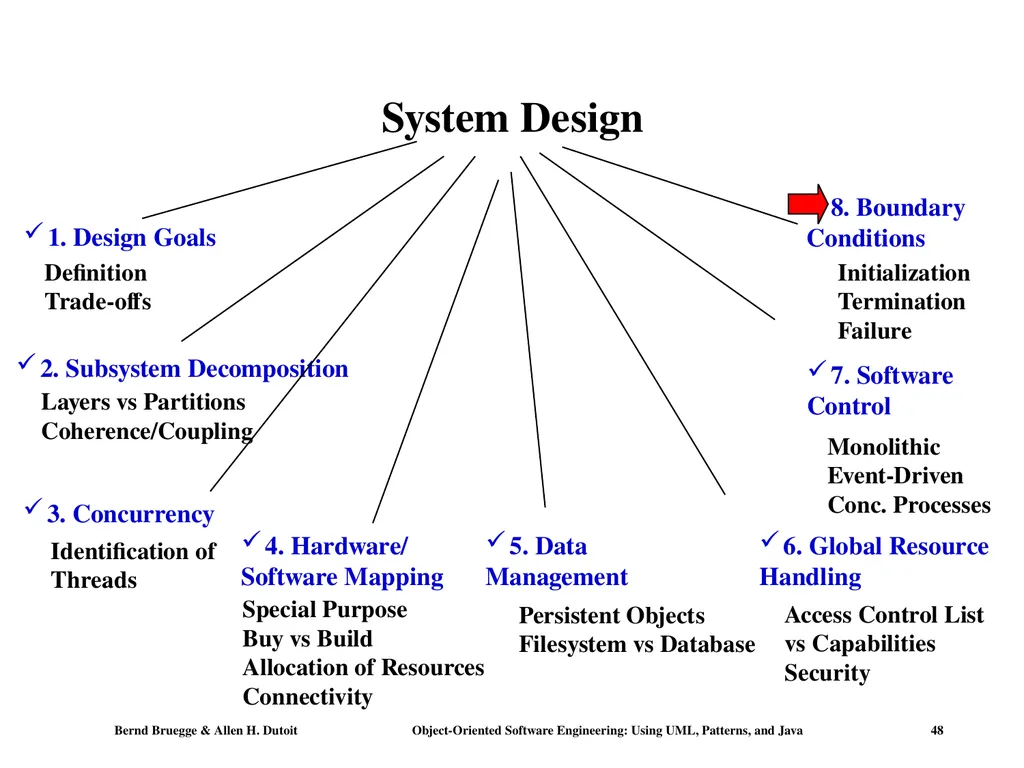
slide48. System Design 4. Hardware/
Software Mapping<br>
slide49. 8. Boundary Conditions Initialization
The system is brought from a non-initialized state to steady-state
Termination
Resources are cleaned up and other systems are notified upon termination
Failure
Possible failures: Bugs, errors, external problems
Good system design foresees fatal failures and provides mechanisms to deal with them.<br>
slide50. Boundary Condition Questions Initialization
What data need to be accessed at startup time?
What services have to registered?
What does the user interface do at start up time?
Termination
Are single subsystems allowed to terminate?
Are subsystems notified if a single subsystem terminates?
How are updates communicated to the database?
Failure
How does the system behave when a node or communication link fails?
How does the system recover from failure?<br>
slide51. Modeling Boundary Conditions Boundary conditions are best modeled as use cases with actors and objects
We call them boundary use cases or administrative use cases
Actor: the system administrator
Interesting use cases:
Start up of a subsystem
Start up of the full system
Termination of a subsystem
Error in a subsystem or component, failure of a subsystem or component.<br>
slide52. Example: Boundary Use Case for ARENA Let us assume, we identified the subsystem AdvertisementServer during system design
This server takes a big load during the holiday season
During hardware software mapping we decide to dedicate a special node for this server
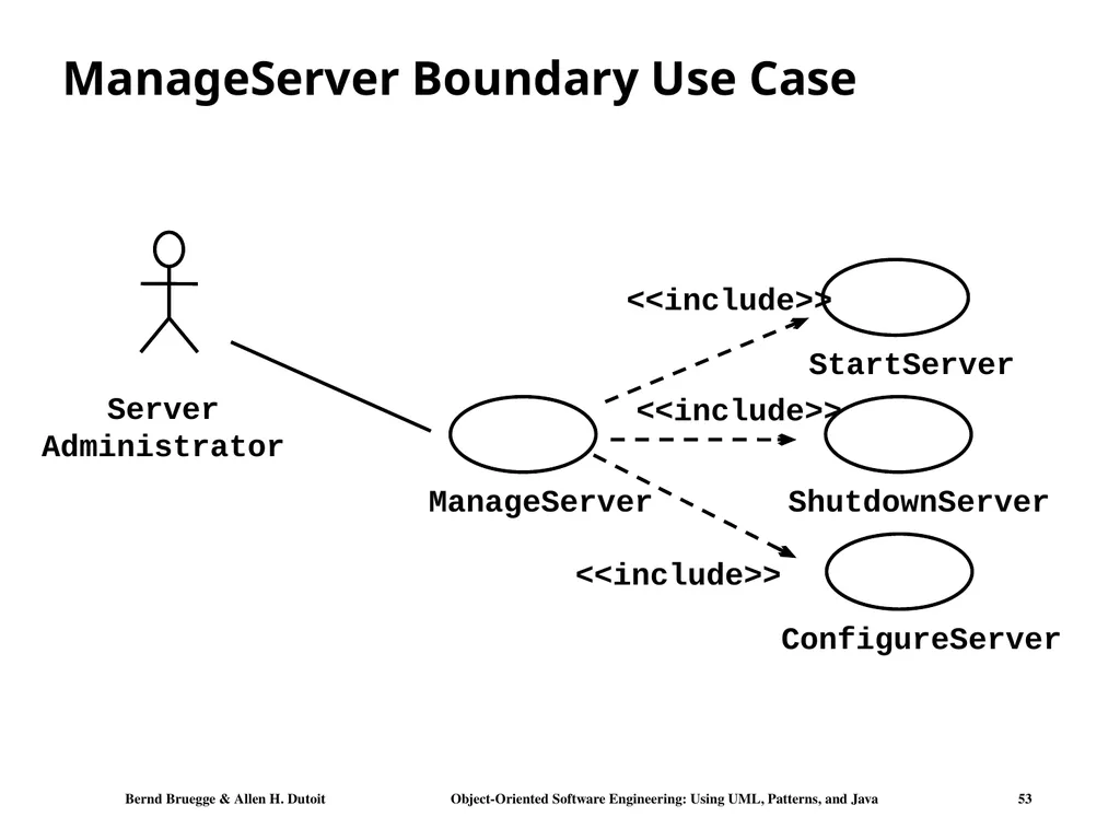
For this node we define a new boundary use case ManageServer
ManageServer includes all the functions necessary to start up and shutdown the AdvertisementServer.<br>
slide53. ManageServer Boundary Use Case Server
Administrator ManageServer StartServer ShutdownServer ConfigureServer <<include>> <<include>> <<include>><br>
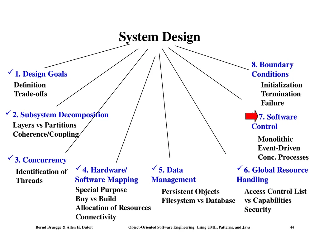
slide54. Summary System design activities:
Concurrency identification
Hardware/Software mapping
Persistent data management
Global resource handling
Software control selection
Boundary conditions
Each of these activities may affect the subsystem decomposition
Two new UML Notations
UML Component Diagram: Showing compile time and runtime dependencies between subsystems
UML Deployment Diagram: Drawing the runtime configuration of the system.<br>
slide2. 1 - Consider a file system with a graphical user interface, such as Macintosh’s Finder, Microsoft’sWindows Explorer, or Linux’s KDE. The following objects were identified from a use case describing how to copy a file from a floppy disk to a hard disk: File, Icon, TrashCan, Folder, Disk, Pointer. Specify which are entity objects, which are boundary objects, and which are control objects. Entity objects: File, Folder, Disk, TrashCan (if regarded as folder)
Boundary objects: Icon, Pointer, TrashCan (if regarded as icon)
Control objects: none in this example.<br>
slide3. 2 - From the sequence diagram below, draw the corresponding class diagram for 2BWatch. Hint: Start with the participating objects in the sequence diagram.
Warning 1: Actor is not an object!
Warning 2: You need to list attributes for some of the objects.<br>
slide4. SimpleWatch is an instance of 2BWatch
LCDdisplay is an instance of 2BWatchDisplay
Time is an instance of 2BWatchTime
Boundary object: 2BWatchButtons or 2BWatchInput (ok if you left it as attributes)
Messages: pressButton1(), pressButton2(), pressButton1and2() 2BWatchInput
blinkHours(), blinkMinutes(), stopBlinking(), refresh() 2BWatchDisplay
possible attribute: digitBlanking
incrementMinutes(), commitNewTime()
possible attribute: time 2BWatch 2BWatchInput pressButton1()
pressButton2()
pressButton1and2() 2BWatchDisplay 2BWatchTime blinkHours()
blinkMinutes()
stopBlinking()
refresh() digitBlanking incrementMinutes()
commitNewTime() time<br>
slide5. Midterm: Chapters 1-5<br>
slide6. You should know… Use case diagrams
Describe the functional behavior of the system as seen by the user
Used during requirements elicitation
Class diagrams
Describe the static structure of the system: Objects, attributes, associations
Sequence diagrams
Describe the dynamic behavior between objects of the system
State diagrams
Describe the dynamic behavior of an individual object
Activity diagrams
Describe the dynamic behavior of a system, in particular the workflow.<br>
slide7. UML Core Conventions All UML Diagrams are composed of graphs of nodes and edges
Nodes are entities and drawn as rectangles or ovals
Rectangles denote classes or instances
Ovals denote functions Names of Classes are not underlined
SimpleWatch
Firefighter
Names of Instances are underlined
myWatch:SimpleWatch
Joe:Firefighter
An edge between two nodes denotes a relationship between the corresponding entities<br>
slide8. Use case diagrams Use case diagrams represent the functionality of the system
from user’s point of view Actor. Use Case System boundary Classifier<br>
slide9. Use case diagrams Use case diagrams represent external behavior
Uses should be verbs
Actor-use relations are marked with an edge:
Which actor is related to which use (what does an actor do?)
Relationships between uses:
Extends Relationship
To represent seldom invoked use cases or exceptional functionality
Includes Relationship
To represent functional behavior common to more than one use case.
Warning: extends/includes relationships are shown ONLY in Use Cases. NOT in Statechart, sequence, class diagrams!
Hierarchy between uses:
“Kind-of” and “Part-of”: they can be in class diagrams too<br>
slide10. The <<extends>> Relationship <<extends>> relationships model exceptional or seldom invoked cases
The exceptional event flows are factored out of the main event flow for clarity
The direction of an <<extends>> relationship is to the extended use case
Use cases representing exceptional flows can extend more than one use case.<br>
slide11. The <<includes>> Relationship <<includes>> relationship represents common functionality needed in more than one use case
<<includes>> behavior is factored out for reuse, not because it is an exception
The direction of a <<includes>> relationship is to the using use case (unlike the direction of the <<extends>> relationship).<br>
slide12. Class diagrams 1 2 push() release() 1 Watch Operations state PushButton Attribute Class diagrams represent the structure of the system Class Association Multiplicity<br>
slide13. Class Diagrams Class diagrams represent the structure of the system
Used
during requirements analysis to model application domain concepts
during system design to model subsystems
during object design to specify the detailed behavior and attributes of classes.<br>
slide14. Classes A class represents a concept
A class encapsulates state (attributes) and behavior (operations) Signature The class name is the only mandatory information Each attribute has a type
Each operation has a signature Type<br>
slide15. Actor vs Class vs Object Actor
An entity outside the system to be modeled, interacting with the system (“Passenger”)
Class
An abstraction modeling an entity in the application or solution domain
The class is part of the system model (“User”, “Ticket distributor”, “Server”)
Object
A specific instance of a class (“Joe, the passenger who is purchasing a ticket from the ticket distributor”).<br>
slide16. Message Sequence diagrams :Time Object Activation Sequence diagrams represent the behavior of a system
as messages (“interactions”) between different objects Actor Lifeline<br>
slide17. Sequence Diagrams Used during analysis
To refine use case descriptions
to find additional objects (“participating objects”)
Used during system design
to refine subsystem interfaces
Instances are represented by rectangles. Actors by sticky figures
Lifelines are represented by dashed lines
Messages are represented by arrows
Activations are represented by narrow rectangles. Focus on
control flow Messages ->
Operations on
participating Object<br>
slide18. Sequence Diagrams can also model the Flow of Data The source of an arrow indicates the activation which sent the message
Horizontal dashed arrows indicate data flow, for example return results from a message Dataflow …continued on next slide...<br>
slide19. Sequence Diagrams: Iteration & Condition Iteration is denoted by a * preceding the message name
Condition is denoted by boolean expression in [ ] before the message name ChangeProcessor Iteration Condition …continued on next slide... …continued from previous slide... *<br>
slide20. Creation and destruction Creation is denoted by a message arrow pointing to the object
Destruction is denoted by an X mark at the end of the destruction activation
In garbage collection environments, destruction can be used to denote the end of the useful life of an object. ChangeProcessor …continued from previous slide... Creation of Ticket Destruction of Ticket<br>
slide21. Sequence Diagram Properties UML sequence diagram represent behavior in terms of interactions
One sequence diagram for one scenario (flow of events)
Useful to identify or find missing objects
Time consuming to build, but worth the investment
Complement the class diagrams (which represent structure).
The participating objects are objects (i.e. instances), NOT classes
Class of an object implements the messages that object receives<br>
slide22. Statechart diagrams State Initial state Final state Transition Event Represent behavior of a single object with interesting dynamic behavior.<br>
slide23. Activity Diagrams An activity diagram is a special case of a state chart diagram
The states are activities (“functions”)
An activity diagram is useful to depict the workflow in a system<br>
slide24. Activity Diagrams allow to model Decisions Decision<br>
slide25. Activity Diagrams can model Concurrency Synchronization of multiple activities
Splitting the flow of control into multiple threads Synchronization Splitting<br>
slide26. Activity Diagrams: Grouping of Activities Activities may be grouped into swimlanes to denote the object or subsystem that implements the activities. Open Incident Allocate Resources Coordinate Resources Document Incident Archive Incident Dispatcher FieldOfficer<br>
slide27. Types of Requirements Functional requirements
Describe the interactions between the system and its environment independent from the implementation
“An operator must be able to define a new game. “
Nonfunctional requirements
Aspects not directly related to functional behavior.
“The response time must be less than 1 second”
Constraints
Imposed by the client or the environment
“The implementation language must be Java “
Called “Pseudo requirements” in the text book.<br>
slide28. Functional vs. Nonfunctional Requirements Functional Requirements
Describe user tasks that the system needs to support
Phrased as actions
“Advertise a new league”
“Schedule tournament”
“Notify an interest group” Nonfunctional Requirements
Describe properties of the system or the domain
Phrased as constraints or negative assertions
“All user inputs should be acknowledged within 1 second”
“A system crash should not result in data loss”.<br>
slide29. Types of Nonfunctional Requirements Usability
Reliability
Robustness
Safety
Performance
Response time
Scalability
Throughput
Availability
Supportability
Adaptability
Maintainability Implementation
Interface
Operation
Packaging
Legal
Licensing (GPL, LGPL)
Certification
Regulation Quality requirements Constraints or Pseudo requirements<br>
slide30. Nonfunctional Requirements: Examples “Spectators must be able to watch a match without prior registration and without prior knowledge of the match.”
Usability Requirement
“The system must be running 95% of the time”
Reliability Requirement
“The system must support 10 parallel tournaments”
Performance Requirement
“The operator must be able to add new games without modifications to the existing system.”
Supportability Requirement<br>
slide31. Different types of Objects Entity Objects
Represent the persistent information tracked by the system (Application domain objects, also called “Business objects”)
Boundary Objects
Represent the interaction between the user and the system
Control Objects
Represent the control tasks performed by the system.<br>
slide32. Finding Participating Objects in Use Cases Pick a use case and look at flow of events
Do a textual analysis (noun-verb analysis)
Nouns are candidates for objects/classes
Verbs are candidates for operations
This is also called Abbott’s Technique
After objects/classes are found, identify their types
Identify real world entities that the system needs to keep track of (FieldOfficer Entity Object)
Identify real world procedures that the system needs to keep track of (EmergencyPlan Control Object)
Identify interface artifacts (PoliceStation Boundary Object).<br>
slide33. Example for using the Technique The customer enters the store to buy a toy.
It has to be a toy that his daughter likes and it must cost less than 50 Euros.
He tries a videogame, which uses a data glove and a head-mounted display. He likes it.
An assistant helps him.
The suitability of the game depends on the age of the child.
His daughter is only 3 years old.
The assistant recommends another type of toy, namely the boardgame “Monopoly". Flow of Events:<br>
slide34. Mapping parts of speech to model components (Abbott’s Technique)<br>
slide35. Grammatical construct UML Component Concrete Person, Thing Object noun class verb Operation Classifying verb Inheritance Possessive Verb Aggregation modal Verb Constraint Adjective Attribute Intransitive verb Operation (Event) Textual Analysis using Abbott‘s technique Example “Monopoly" “toy" “enters" “is a" ,“either..or",
“kind of…" "Has a ", “consists of" “must be", “less than…" "3 years old" “depends on…."<br>
slide36. The customer enters the store to buy a toy. It has to be a toy that his daughter likes and it must cost less than 50 Euro. He tries a videogame, which uses a data glove and a head-mounted display. He likes it. Generating a Class Diagram from Flow of Events An assistant helps him. The suitability of the game depends on the age of the child. His daughter is only 3 years old. The assistant recommends another type of toy, namely a boardgame. The customer buy the game and leaves the store Customer Flow of events:<br>
slide37. Chapter 7 System Design: Addressing Design Goals<br>
slide38. System Design 4. Hardware/
Software Mapping<br>
slide39. 6. Global Resource Handling Discusses access control
Describes access rights for different classes of actors
Describes how object guard against unauthorized access.<br>
slide40. Defining Access Control In multi-user systems different actors usually have different access rights to different functionality and data
How do we model these accesses?
During analysis we model them by associating different use cases with different actors
During system design we model them determining which objects are shared among actors.<br>
slide41. Access Matrix We model access on classes with an access matrix:
The rows of the matrix represents the actors of the system
The column represent classes whose access we want to control
Access Right: An entry in the access matrix. It lists the operations that can be executed on instances of the class by the actor.<br>
slide42. Access Matrix Example Arena League Operator LeagueOwner Player Spectator Tournament <<create>> archive() schedule() view() applyFor() view() view() <<create>> createUser() view () view () view() applyForPlayer() view() applyForOwner() <<create>> archive() view() subscribe() view() subscribe() edit () Match <<create>> end() play() forfeit() view() replay() Actors Classes Access Rights<br>
slide43. Global Resource Questions Does the system need authentication?
If yes, what is the authentication scheme?
User name and password? Access control list
Tickets? Capability-based
What is the user interface for authentication?
Does the system need a network-wide name server?
How is a service known to the rest of the system?
At runtime? At compile time?
By Port?
By Name?<br>
slide44. System Design 4. Hardware/
Software Mapping<br>
slide45. 7. Decide on Software Control Two major design choices:
1. Choose implicit control
No control object
2. Choose explicit control
Centralized or decentralized
Centralized control:
Procedure-driven: Control resides within program code.
Event-driven: Control resides within a dispatcher calling functions via callbacks.
Decentralized control
Control resides in several independent objects.
Examples: Message based system, RMI
Possible speedup by mapping the objects on different processors, increased communication overhead.<br>
slide46. Centralized vs. Decentralized Designs Centralized Design
One control object or subsystem ("spider") controls everything
Pro: Change in the control structure is very easy
Con: The single control object is a possible performance bottleneck
Decentralized Design
Not a single object is in control, control is distributed; That means, there is more than one control object
Con: The responsibility is spread out
Pro: Fits nicely into object-oriented development<br>
slide47. Centralized vs. Decentralized Designs (2) Should you use a centralized or decentralized design?
Take the sequence diagrams and control objects from the analysis model
Check the participation of the control objects in the sequence diagrams
If the sequence diagram looks like a fork => Centralized design
If the sequence diagram looks like a stair => Decentralized design.<br>
slide48. System Design 4. Hardware/
Software Mapping<br>
slide49. 8. Boundary Conditions Initialization
The system is brought from a non-initialized state to steady-state
Termination
Resources are cleaned up and other systems are notified upon termination
Failure
Possible failures: Bugs, errors, external problems
Good system design foresees fatal failures and provides mechanisms to deal with them.<br>
slide50. Boundary Condition Questions Initialization
What data need to be accessed at startup time?
What services have to registered?
What does the user interface do at start up time?
Termination
Are single subsystems allowed to terminate?
Are subsystems notified if a single subsystem terminates?
How are updates communicated to the database?
Failure
How does the system behave when a node or communication link fails?
How does the system recover from failure?<br>
slide51. Modeling Boundary Conditions Boundary conditions are best modeled as use cases with actors and objects
We call them boundary use cases or administrative use cases
Actor: the system administrator
Interesting use cases:
Start up of a subsystem
Start up of the full system
Termination of a subsystem
Error in a subsystem or component, failure of a subsystem or component.<br>
slide52. Example: Boundary Use Case for ARENA Let us assume, we identified the subsystem AdvertisementServer during system design
This server takes a big load during the holiday season
During hardware software mapping we decide to dedicate a special node for this server
For this node we define a new boundary use case ManageServer
ManageServer includes all the functions necessary to start up and shutdown the AdvertisementServer.<br>
slide53. ManageServer Boundary Use Case Server
Administrator ManageServer StartServer ShutdownServer ConfigureServer <<include>> <<include>> <<include>><br>
slide54. Summary System design activities:
Concurrency identification
Hardware/Software mapping
Persistent data management
Global resource handling
Software control selection
Boundary conditions
Each of these activities may affect the subsystem decomposition
Two new UML Notations
UML Component Diagram: Showing compile time and runtime dependencies between subsystems
UML Deployment Diagram: Drawing the runtime configuration of the system.<br>