04
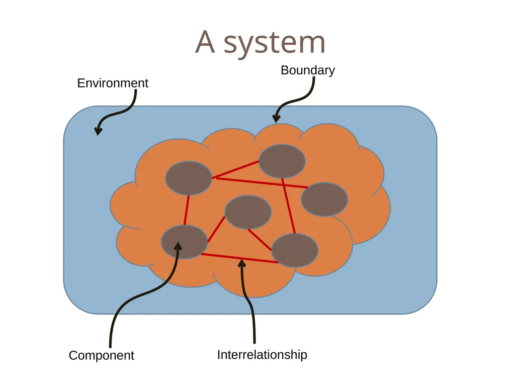
A system Component Interrelationship Boundary Environment<br>
05
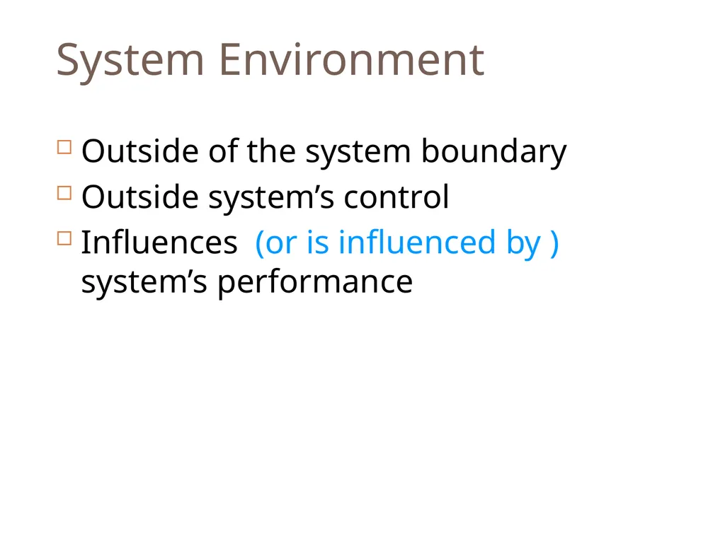
System Environment Outside of the system boundary
Outside system’s control
Influences (or is influenced by ) system’s performance<br>
06
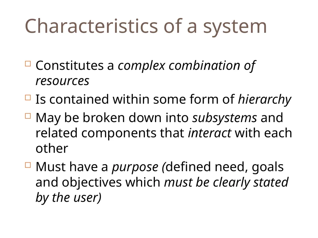
Characteristics of a system Constitutes a complex combination of resources
Is contained within some form of hierarchy
May be broken down into subsystems and related components that interact with each other
Must have a purpose (defined need, goals and objectives which must be clearly stated by the user)<br>
07
3 Phase Lifecycle Definition
Development
Deployment<br>
08
Module 2 – Bringing systems into being Remember remember…<br>
09
Objective for Module 2 Principles and processes
To “engineer” a system
Integration and iteration in system design
Implementation of systems engineering and analysis<br>
10
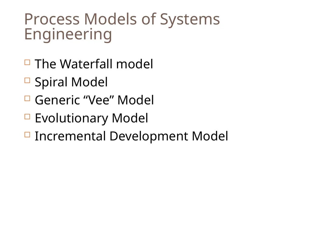
Process Models of Systems Engineering The Waterfall model
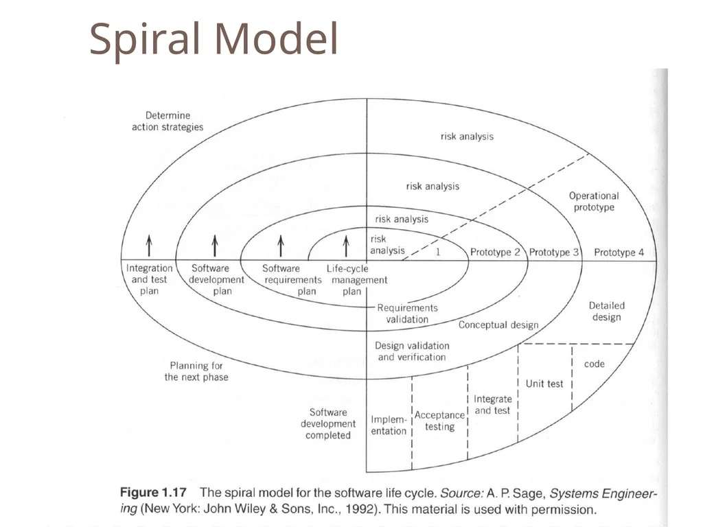
Spiral Model
Generic “Vee” Model
Evolutionary Model
Incremental Development Model<br>
11
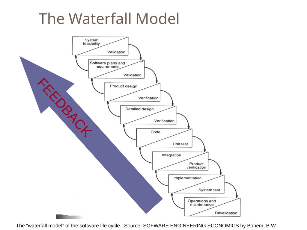
The Waterfall Model The “waterfall model” of the software life cycle. Source: SOFWARE ENGINEERING ECONOMICS by Bohem, B.W. FEEDBACK<br>
13
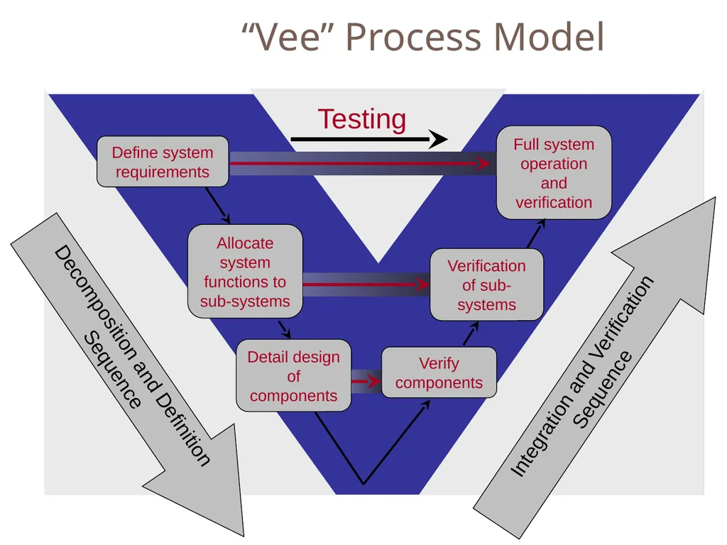
“Vee” Process Model Define system requirements Allocate system functions to sub-systems Detail design of components Full system operation and verification Verification of sub-systems Verify components Integration and Verification Sequence Decomposition and Definition Sequence Testing<br>
14
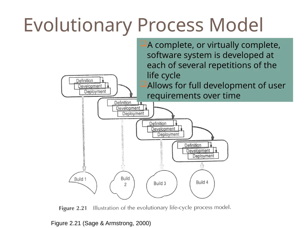
Evolutionary Process Model A complete, or virtually complete, software system is developed at each of several repetitions of the life cycle
Allows for full development of user requirements over time Figure 2.21 (Sage & Armstrong, 2000)<br>
15
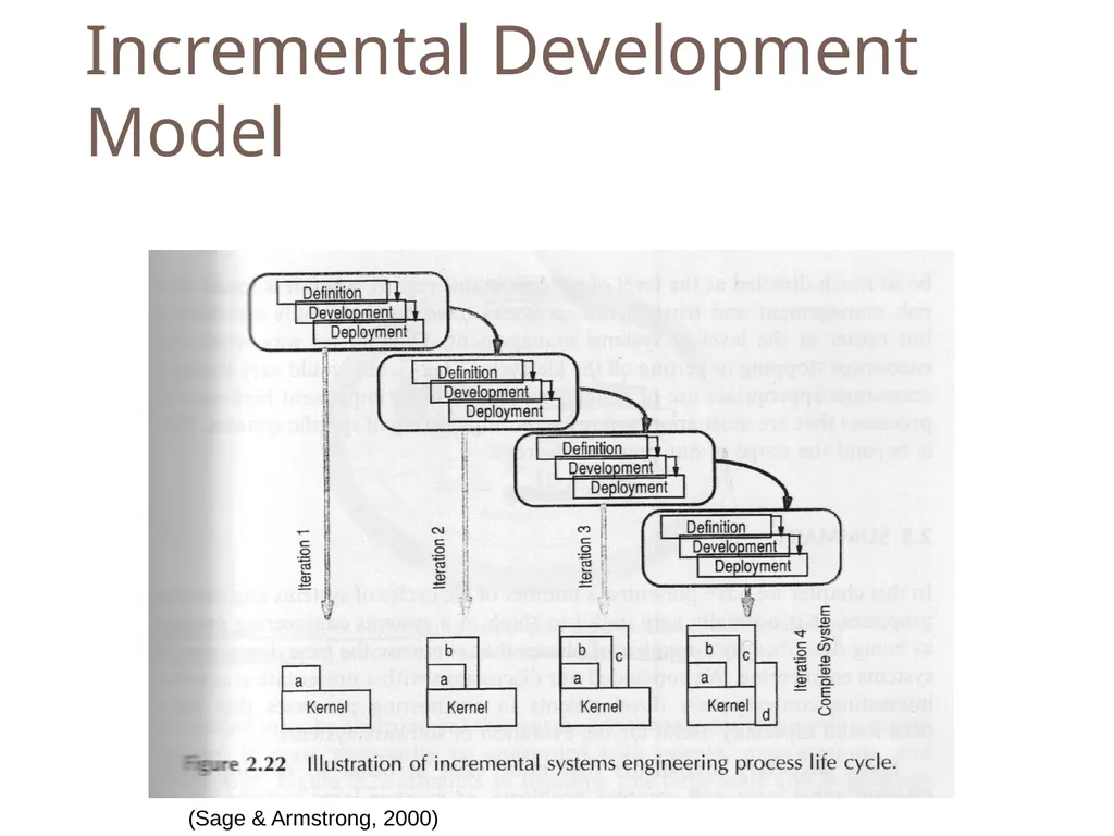
Incremental Development Model (Sage & Armstrong, 2000)<br>
16
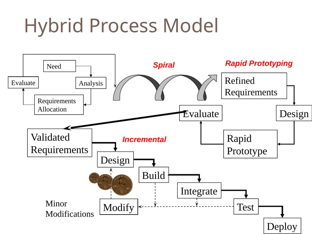
Hybrid Process Model<br>
17
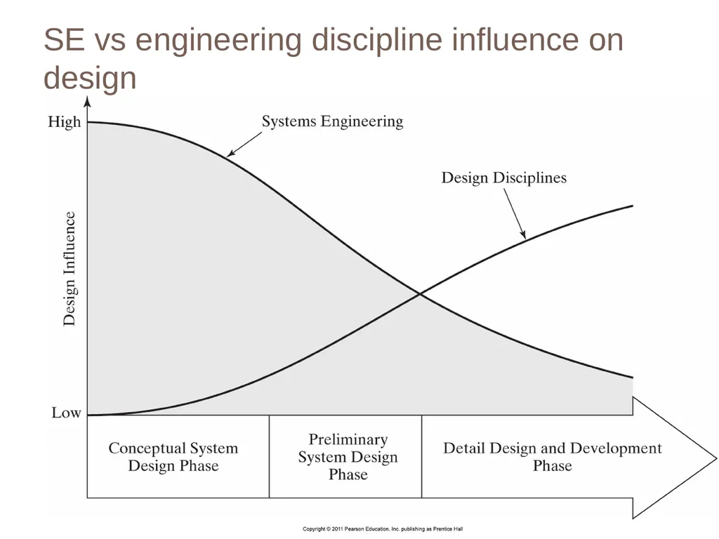
SE vs engineering discipline influence on design<br>
18
Module 3 – Conceptual Design Phase Remember remember…<br>
19
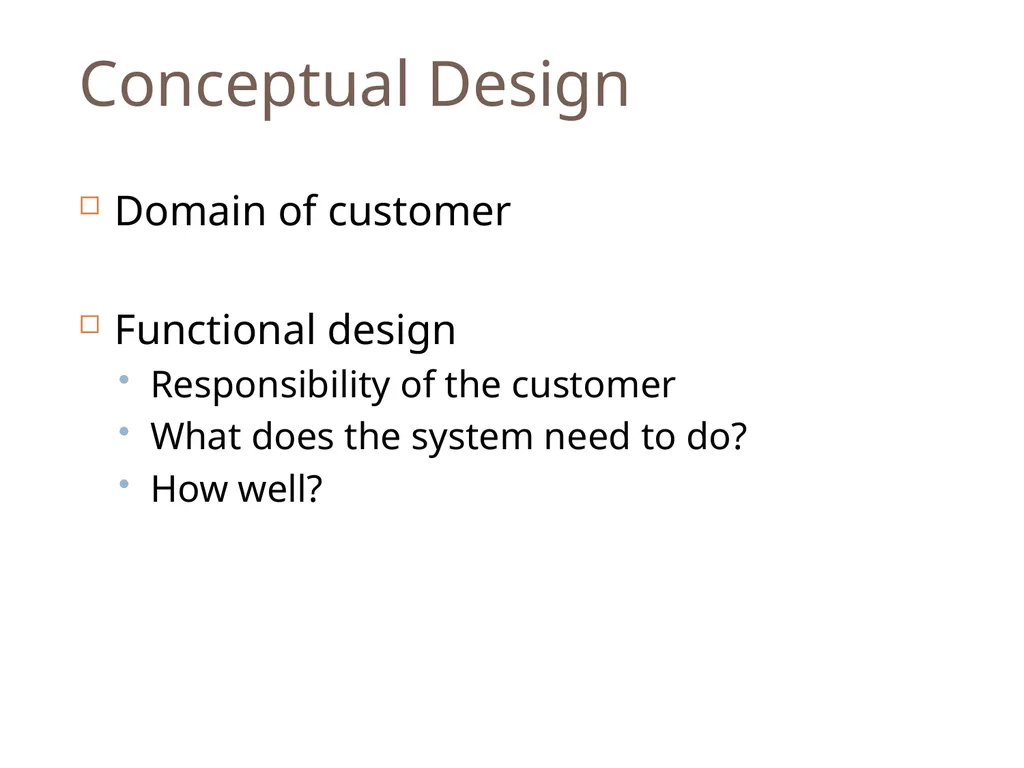
Conceptual Design Domain of customer
Functional design
Responsibility of the customer
What does the system need to do?
How well?<br>
20
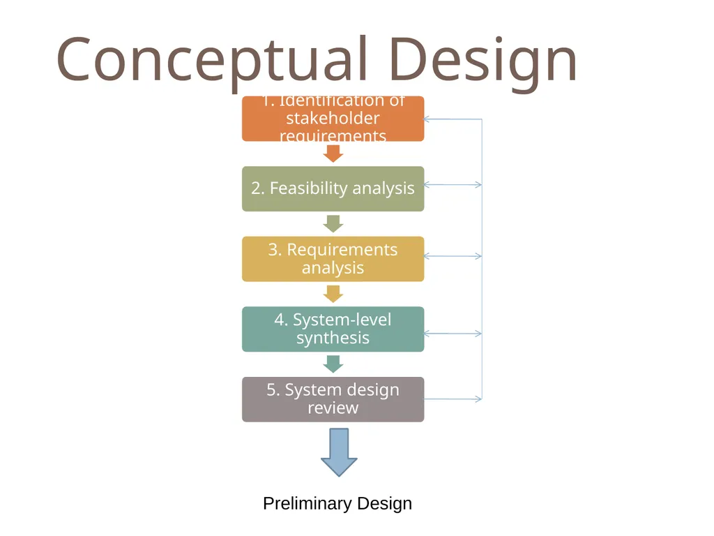
Conceptual Design Preliminary Design<br>
21
Module 4 – Preliminary Design Remember remember…<br>
22
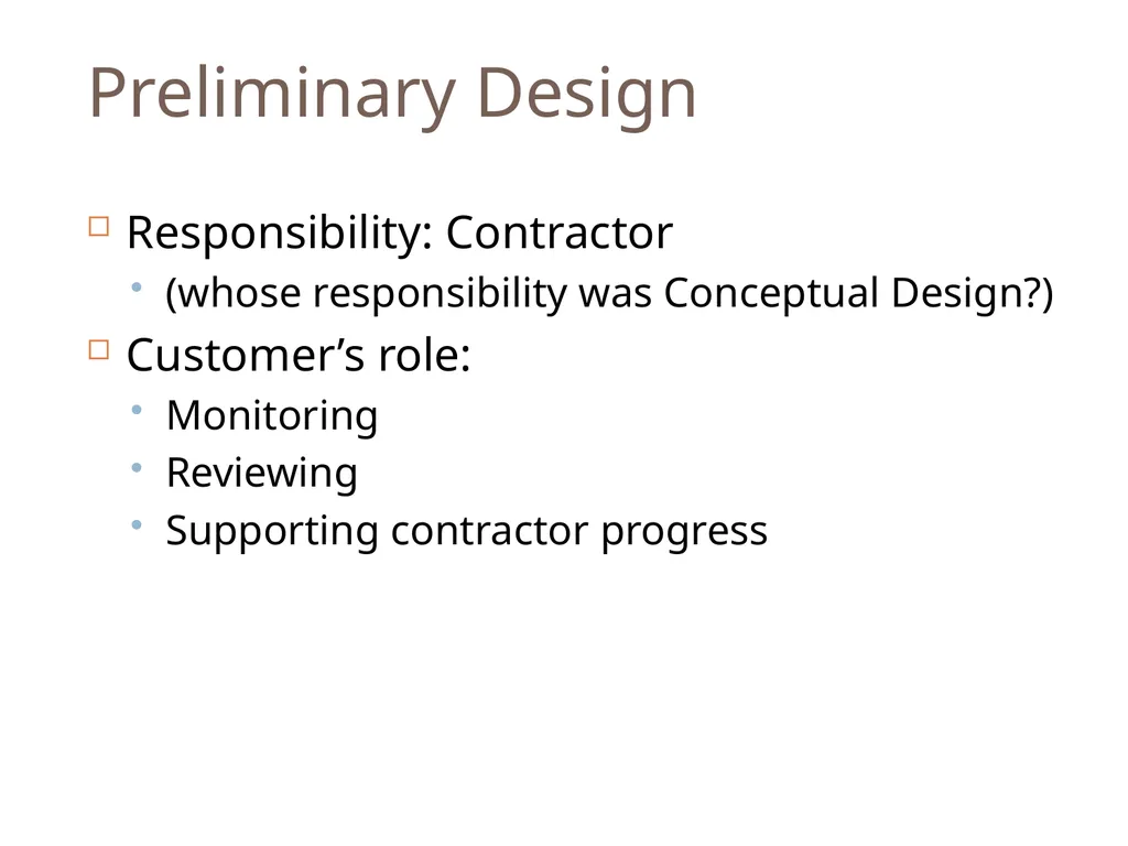
Preliminary Design Responsibility: Contractor
(whose responsibility was Conceptual Design?)
Customer’s role:
Monitoring
Reviewing
Supporting contractor progress<br>
23
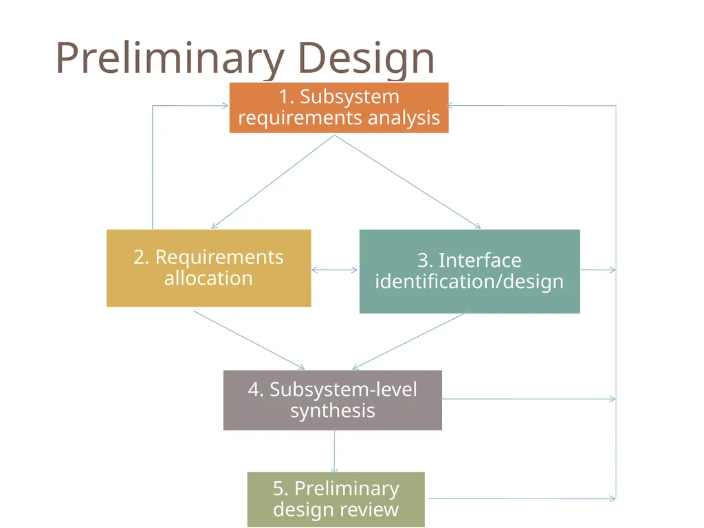
Preliminary Design<br>
24
Module 5 – Detailed Design and Development Remember remember…<br>
26
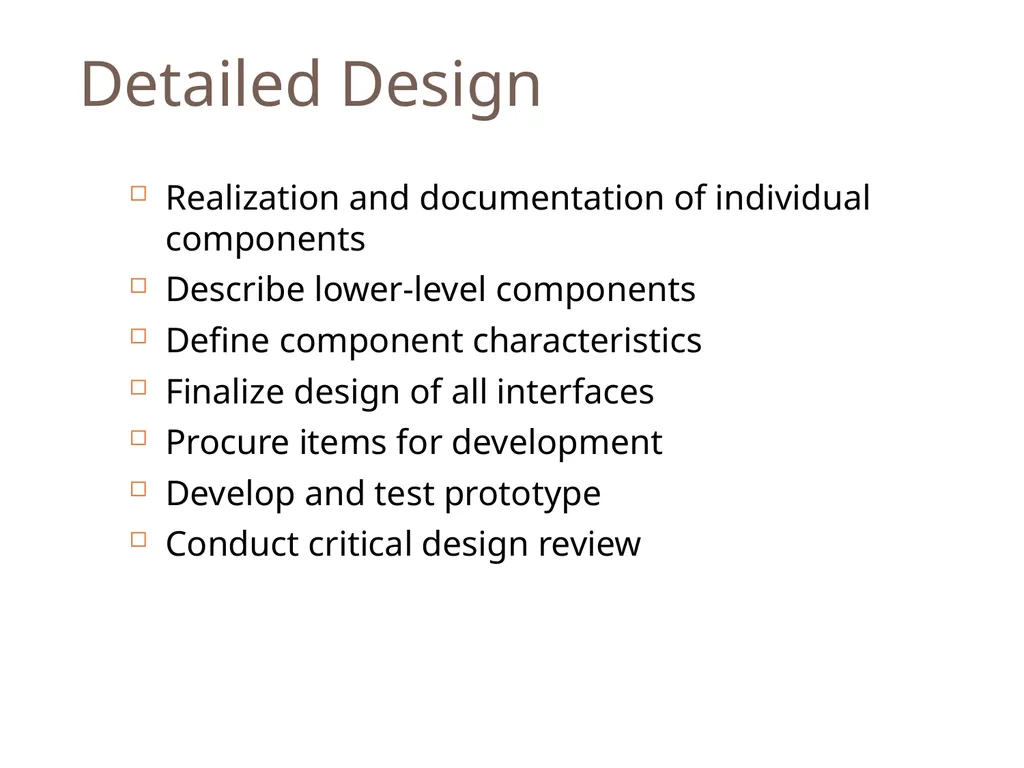
Detailed Design Realization and documentation of individual components
Describe lower-level components
Define component characteristics
Finalize design of all interfaces
Procure items for development
Develop and test prototype
Conduct critical design review<br>
27
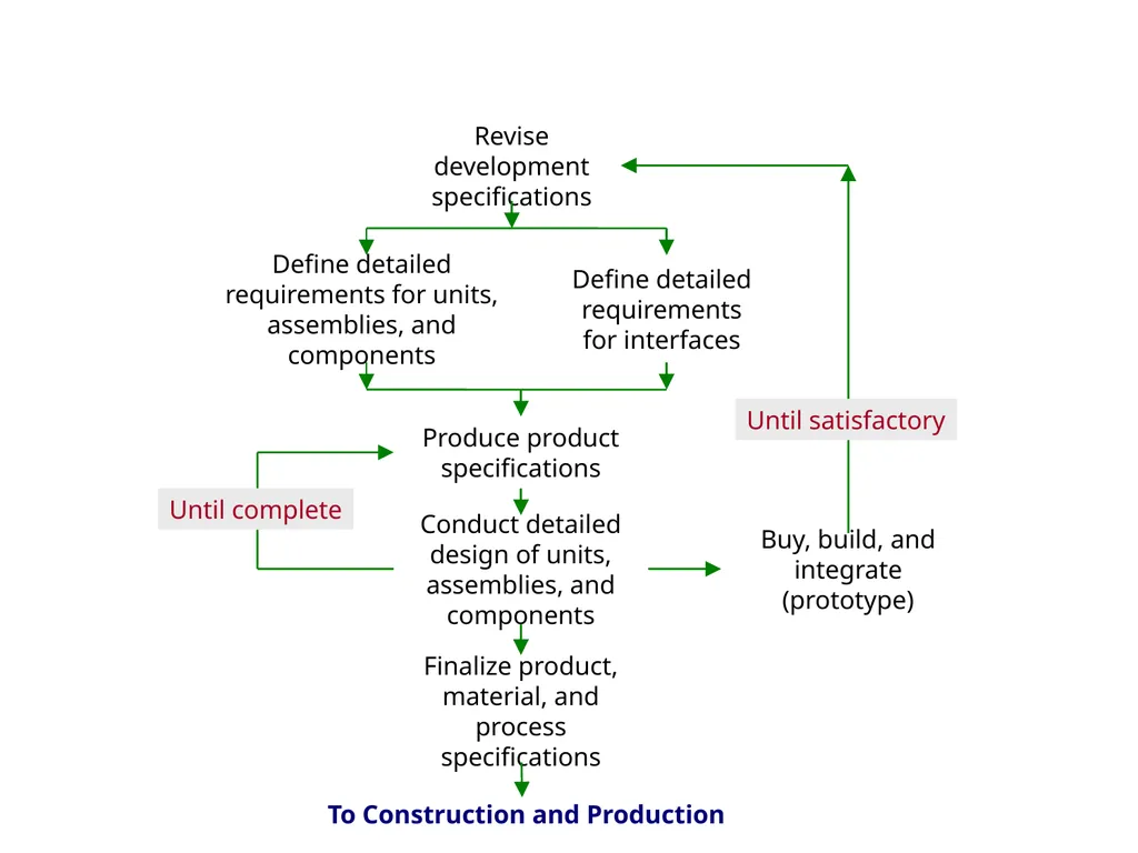
Revise development specifications Define detailed requirements for units, assemblies, and components Define detailed requirements for interfaces Produce product specifications Conduct detailed design of units, assemblies, and components Buy, build, and integrate (prototype) Finalize product, material, and process specifications Until satisfactory Until complete To Construction and Production Detailed Design and �Development Processes<br>
28
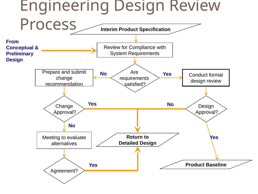
Engineering Design Review Process From Conceptual & Preliminary
Design Interim Product Specification Review for Compliance with System Requirements Product Baseline Meeting to evaluate alternatives Change
Approval? Yes No Are
requirements
satisfied? Prepare and submit change recommendation Conduct formal design review Yes Agreement? Yes No Design
Approval? Yes No Return to
Detailed Design<br>
29
Module 6 – System Test, Evaluation and Validation Remember remember…<br>
30
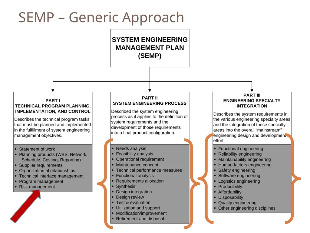
Objectives of this Module Systems Engineering Management/SEMP
Risk Management
System Test, Evaluation and Validation<br>
31
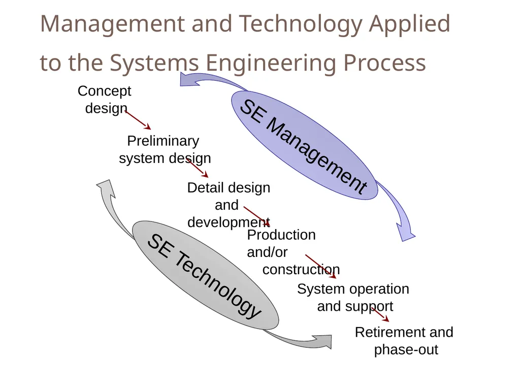
Management and Technology Applied to the Systems Engineering Process<br>
32
SEMP – Generic Approach<br>
33
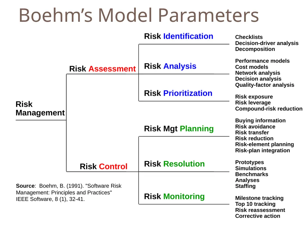
Boehm’s Model Parameters Risk
Management Risk Identification Risk Analysis Risk Prioritization Risk Mgt Planning Risk Resolution Risk Monitoring Checklists
Decision-driver analysis
Decomposition
Performance models
Cost models
Network analysis
Decision analysis
Quality-factor analysis
Risk exposure
Risk leverage
Compound-risk reduction
Buying information
Risk avoidance
Risk transfer
Risk reduction
Risk-element planning
Risk-plan integration
Prototypes
Simulations
Benchmarks
Analyses
Staffing
Milestone tracking
Top 10 tracking
Risk reassessment
Corrective action Risk Control Risk Assessment Source: Boehm, B. (1991). "Software Risk Management: Principles and Practices" IEEE Software, 8 (1), 32-41.<br>
34
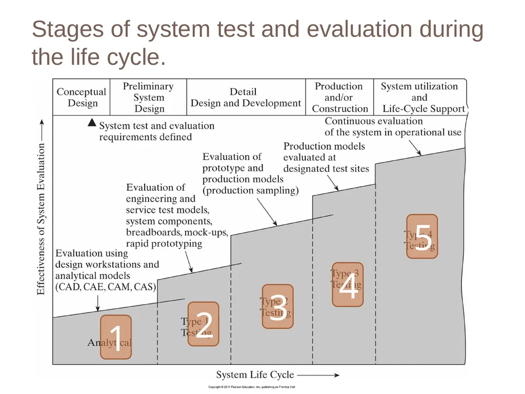
Stages of system test and evaluation during the life cycle. 1 2 3 4 5<br>
35
Module 7 – MidTerms! Remember remember…<br>
36
Module 8 – Alternatives and Models in Decision Making Remember remember…<br>
37
Objectives Decision Analysis Tools
Decision Making under Uncertainty
Decision Making under Risk
Modeling and Simulation<br>
38
Decision Analysis Tools Decision Trees
Decision Matrix (Pay off Matrix)
Cost/Benefit Analysis
Force Field Analysis
Grid Analysis
Paired Comparison Analysis
Intuition<br>
39
IMPORTANT: Uncertainty = No Probability
Risk = Probability<br>
40
Decision Making Under Uncertainty Maximax Criterion
Maximin Criterion
Hurwicz Criterion
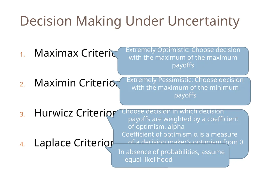
Laplace Criterion Extremely Optimistic: Choose decision with the maximum of the maximum payoffs Extremely Pessimistic: Choose decision with the maximum of the minimum payoffs Choose decision in which decision payoffs are weighted by a coefficient of optimism, alpha
Coefficient of optimism α is a measure of a decision maker’s optimism from 0 (completely pessimistic) to 1 (completely optimistic)\ In absence of probabilities, assume equal likelihood<br>
41
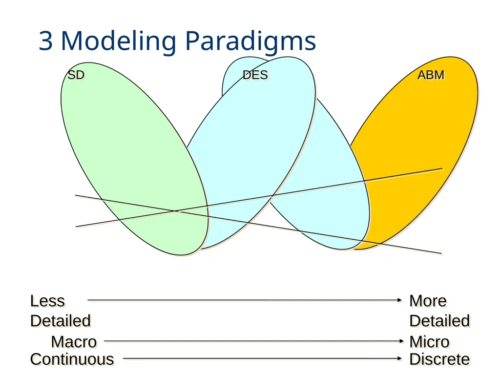
3 Modeling Paradigms SD DES ABM Macro Micro Continuous Discrete Less Detailed More Detailed<br>
42
Module 9, 10 – Capability Maturity Model Integration (CMMI) Remember remember…<br>
43
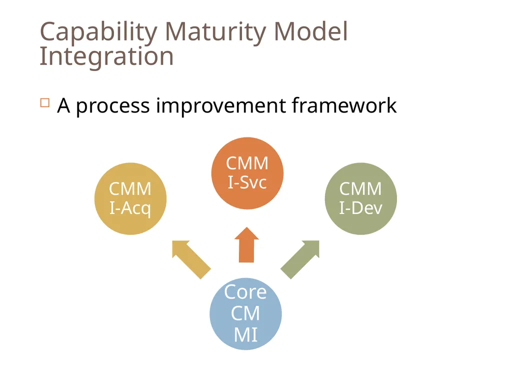
Capability Maturity Model Integration A process improvement framework<br>
45
Module 11 – Model Based Systems Engineering Part 1 Remember remember…<br>
46
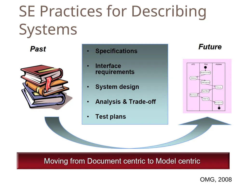
SE Practices for Describing Systems OMG, 2008<br>
47
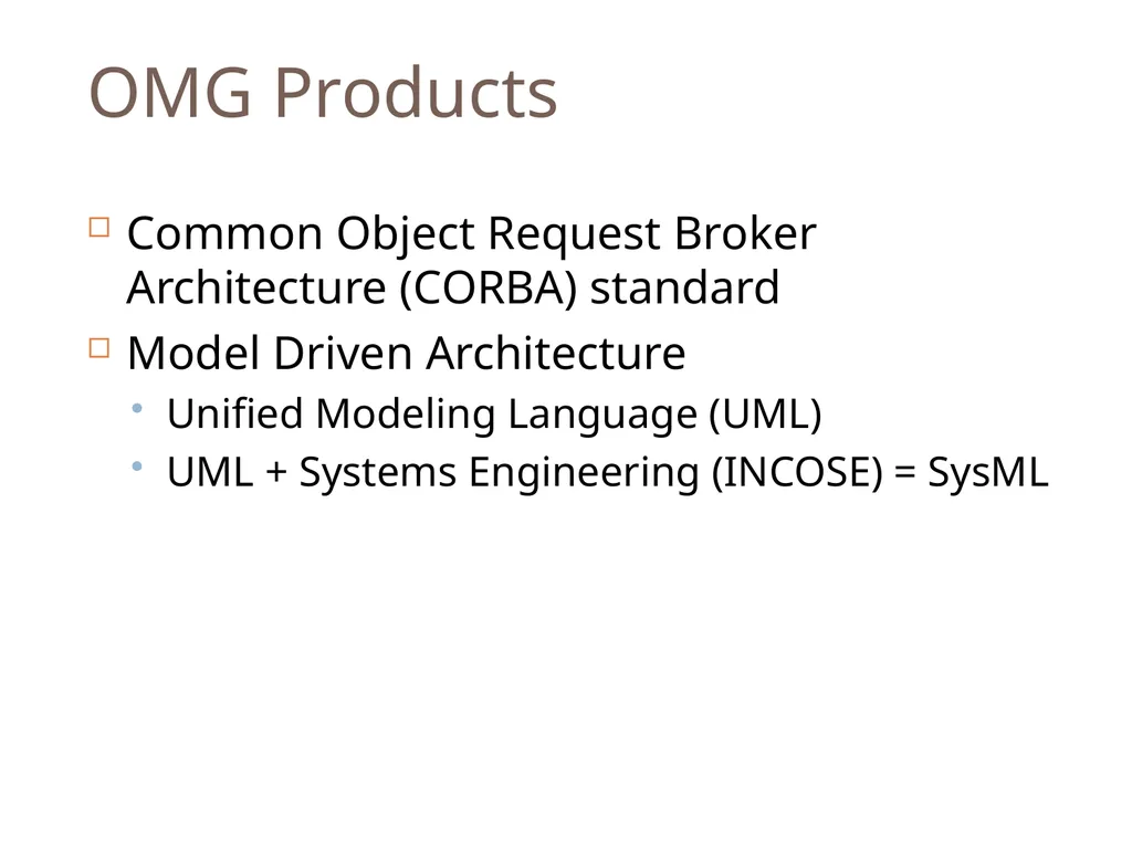
OMG Products Common Object Request Broker Architecture (CORBA) standard
Model Driven Architecture
Unified Modeling Language (UML)
UML + Systems Engineering (INCOSE) = SysML<br>
48
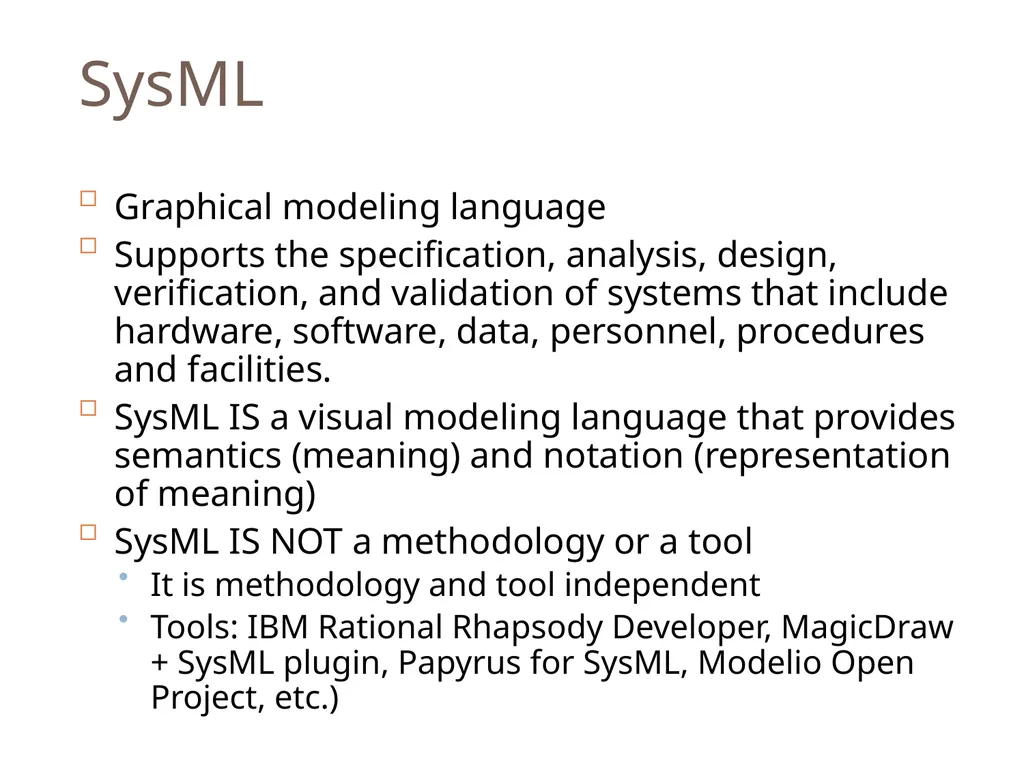
SysML Graphical modeling language
Supports the specification, analysis, design, verification, and validation of systems that include hardware, software, data, personnel, procedures and facilities.
SysML IS a visual modeling language that provides semantics (meaning) and notation (representation of meaning)
SysML IS NOT a methodology or a tool
It is methodology and tool independent
Tools: IBM Rational Rhapsody Developer, MagicDraw + SysML plugin, Papyrus for SysML, Modelio Open Project, etc.)<br>
49
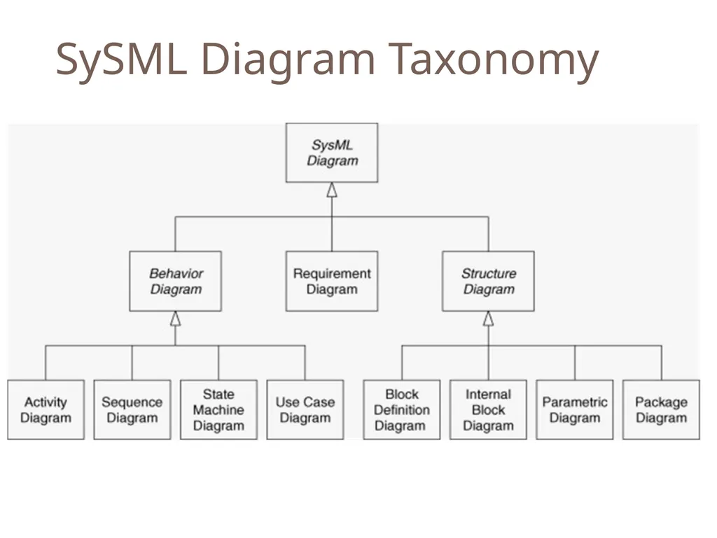
SySML Diagram Taxonomy<br>
50
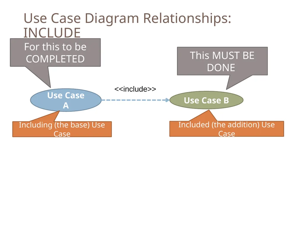
Use Case Diagram Relationships: INCLUDE This MUST BE DONE For this to be COMPLETED<br>
51
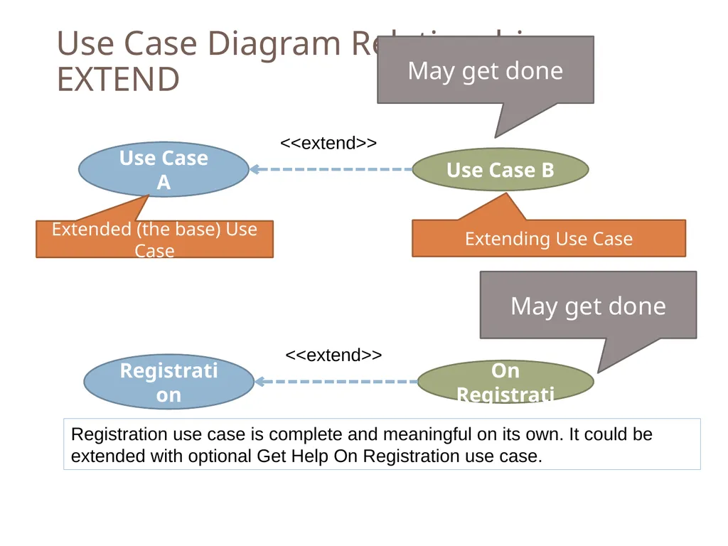
Use Case Diagram Relationships: EXTEND May get done May get done<br>
52
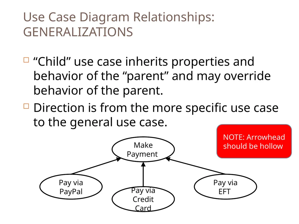
Use Case Diagram Relationships: GENERALIZATIONS “Child” use case inherits properties and behavior of the “parent” and may override behavior of the parent.
Direction is from the more specific use case to the general use case. Make Payment Pay via PayPal Pay via EFT Pay via Credit Card NOTE: Arrowhead should be hollow<br>
53
Module 12 – Model Based Systems Engineering Part 2 Remember remember…<br>
54
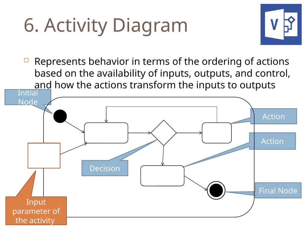
6. Activity Diagram Represents behavior in terms of the ordering of actions based on the availability of inputs, outputs, and control, and how the actions transform the inputs to outputs Initial Node Final Node Decision Action Action Input parameter of the activity<br>
55
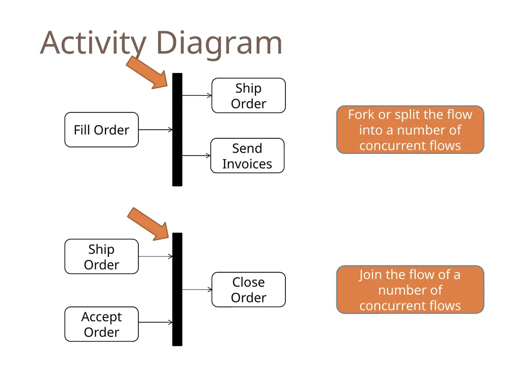
Activity Diagram Fork or split the flow into a number of concurrent flows Join the flow of a number of concurrent flows<br>
56
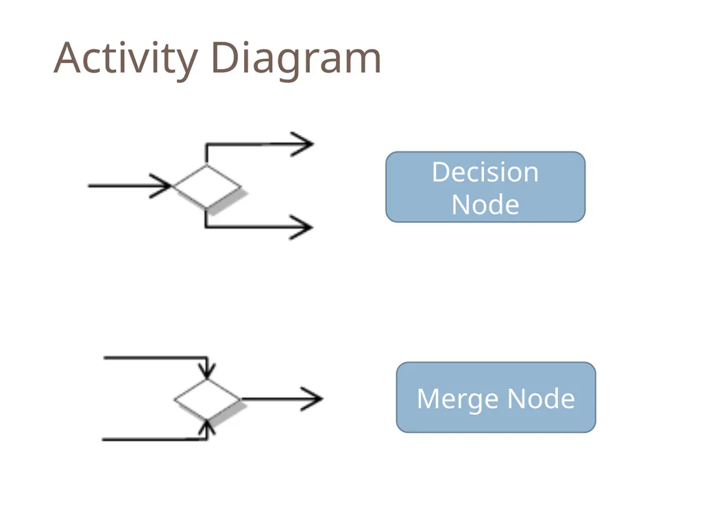
Activity Diagram Decision Node Merge Node<br>
57
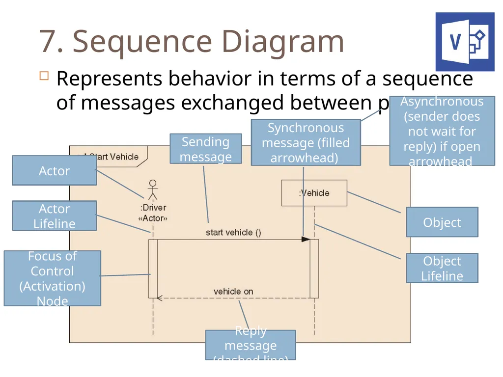
7. Sequence Diagram Represents behavior in terms of a sequence of messages exchanged between parts Actor Actor Lifeline Object Object Lifeline Focus of Control (Activation) Node Sending message Reply message (dashed line) Synchronous message (filled arrowhead) Asynchronous (sender does not wait for reply) if open arrowhead<br>
58
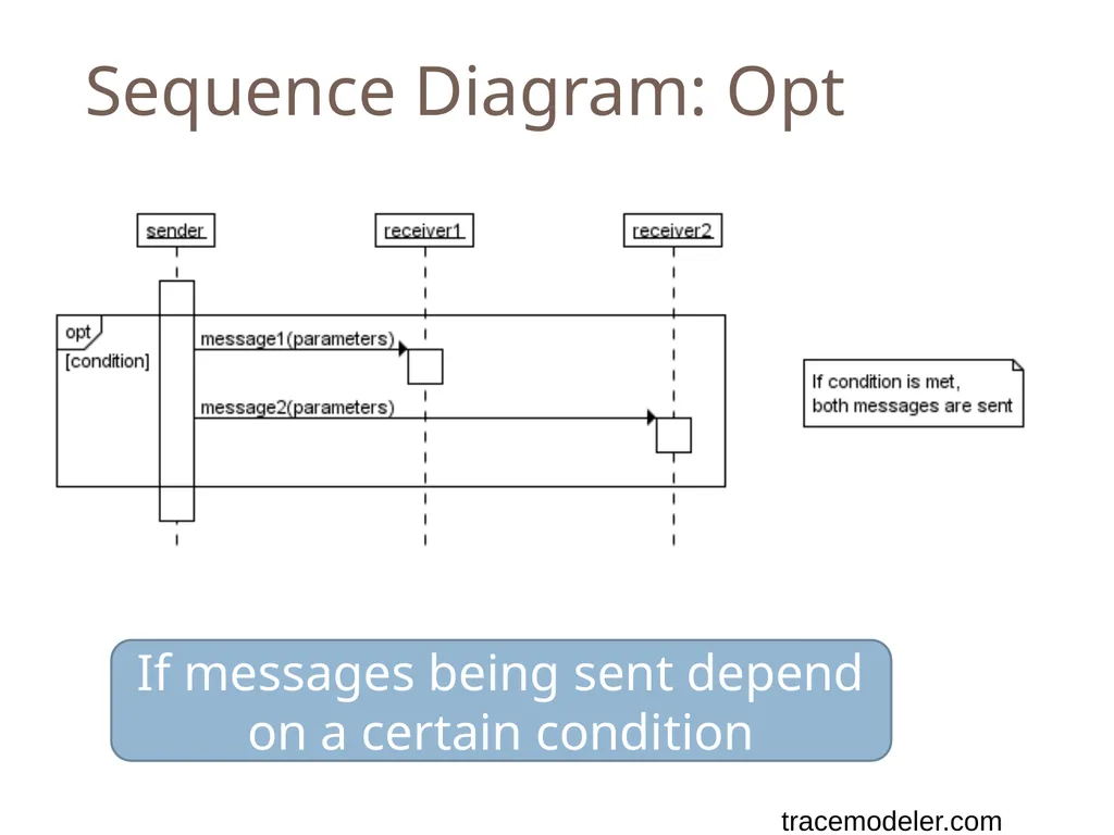
Sequence Diagram: Opt If messages being sent depend on a certain condition tracemodeler.com<br>
59
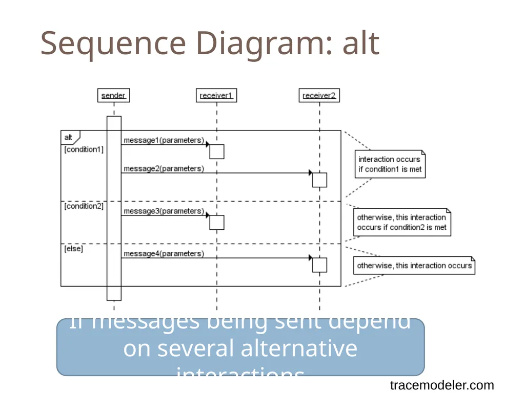
Sequence Diagram: alt If messages being sent depend on several alternative interactions tracemodeler.com<br>
60
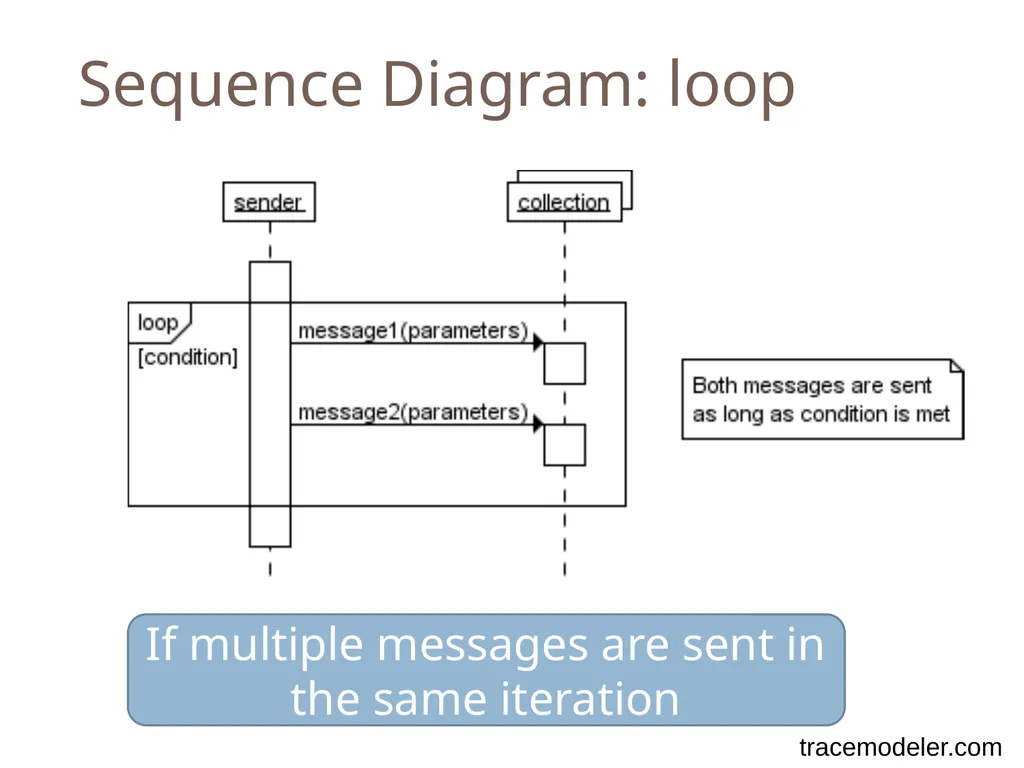
Sequence Diagram: loop If multiple messages are sent in the same iteration tracemodeler.com<br>
61
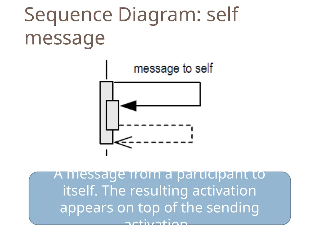
Sequence Diagram: self message A message from a participant to itself. The resulting activation appears on top of the sending activation.<br>
62
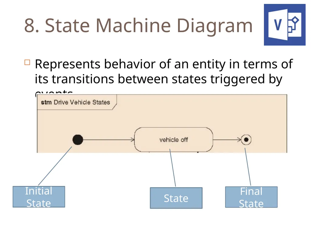
8. State Machine Diagram Represents behavior of an entity in terms of its transitions between states triggered by events Initial State Final State State<br>
63
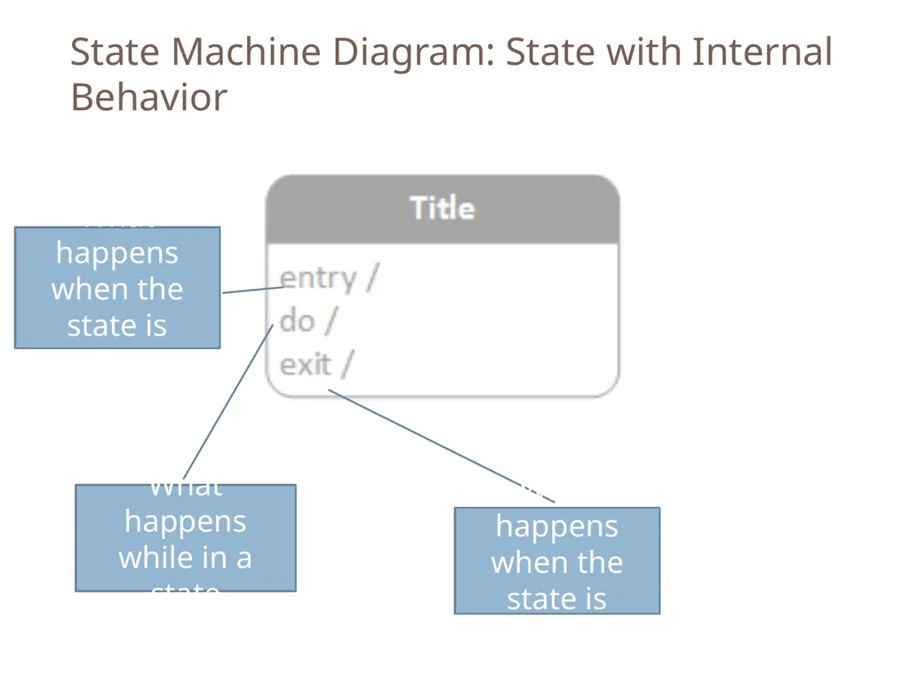
State Machine Diagram: State with Internal Behavior What happens when the state is entered What happens while in a state What happens when the state is exited<br>
64
Module 13 – Model Based Systems Engineering Part 3 Remember remember…<br>
65
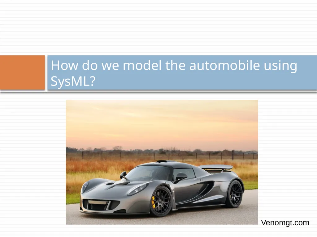
How do we model the automobile using SysML? Venomgt.com<br>