
Software Verification and Validation Lecture No. 7


Description: Software Verification and Validation Lecture No. 7 Software Verification and Validation Agenda Integration Testing Functional decomposition based Integration Call Graph based Integration Path based Integration Module 47: Integration Testing
Related Topics
Download Presentation
"Software Verification and Validation Lecture No. 7" is the property of its rightful owner. Permission is granted to download and print the materials on this website for personal, non-commercial use only, and to display it on your personal computer provided you do not modify the materials and that you retain all copyright notices contained in the materials. By downloading content from our website, you accept the terms of this agreement.
Presentation Transcript
slide1. Software Verification and Validation Lecture No. 7<br>
slide2. Software Verification and Validation Agenda
Integration Testing
Functional decomposition based Integration
Call Graph based Integration
Path based Integration<br>
slide3. Module 47: Integration Testing<br>
slide4. Integration Testing While developing unit test strategy, we consider:
Test Requirement
Documentation requirement
Tools / Test utilities?
Individual units get combined into (sub-) modules
We need to assure if:
they are following design accurately
they are collaborating properly
We do integration testing<br>
slide5. Integration Testing Unit assumptions
All other units are correct
Compiles correctly
Integration assumptions
Unit testing complete
System assumptions
Integration testing complete
Tests occur at port boundary<br>
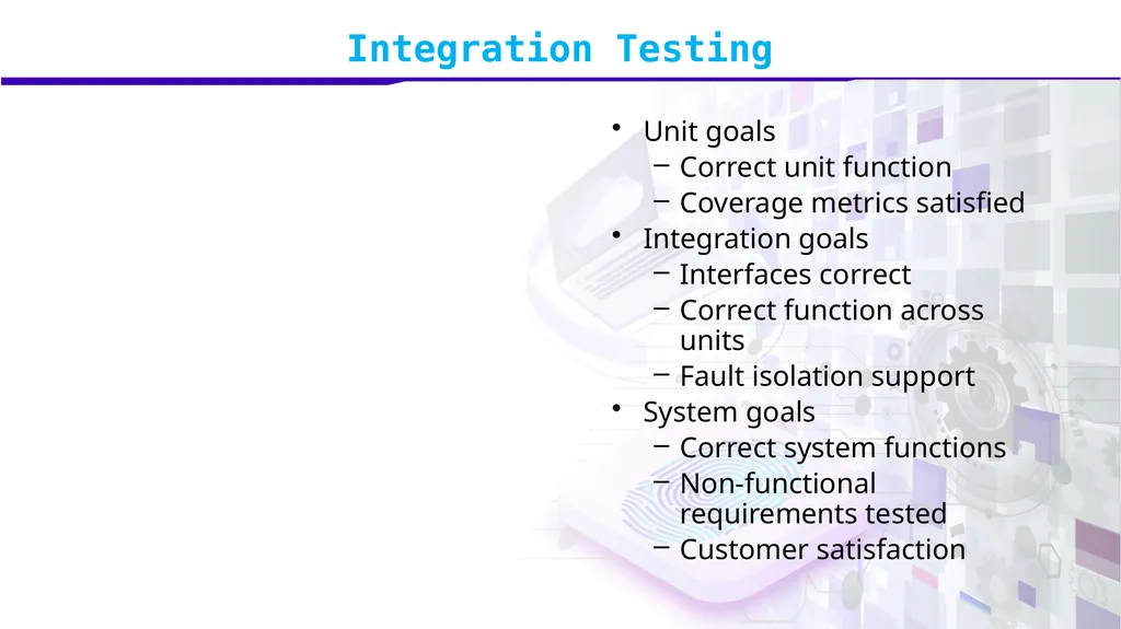
slide6. Integration Testing Unit goals
Correct unit function
Coverage metrics satisfied
Integration goals
Interfaces correct
Correct function across units
Fault isolation support
System goals
Correct system functions
Non-functional requirements tested
Customer satisfaction<br>
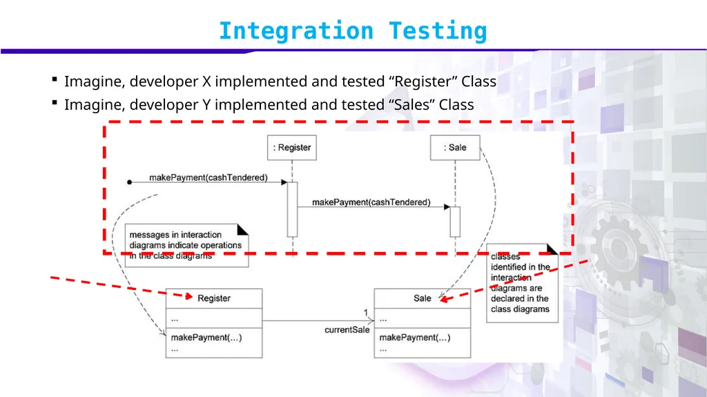
slide7. Integration Testing Imagine, developer X implemented and tested “Register” Class
Imagine, developer Y implemented and tested “Sales” Class<br>
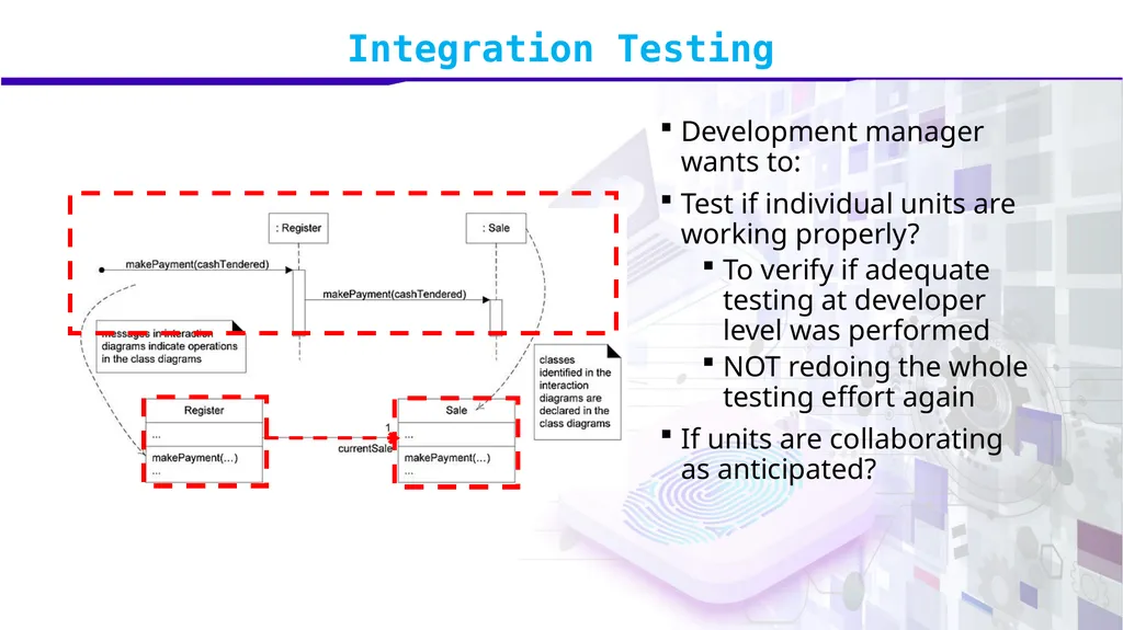
slide8. Integration Testing Development manager wants to:
Test if individual units are working properly?
To verify if adequate testing at developer level was performed
NOT redoing the whole testing effort again
If units are collaborating as anticipated?<br>
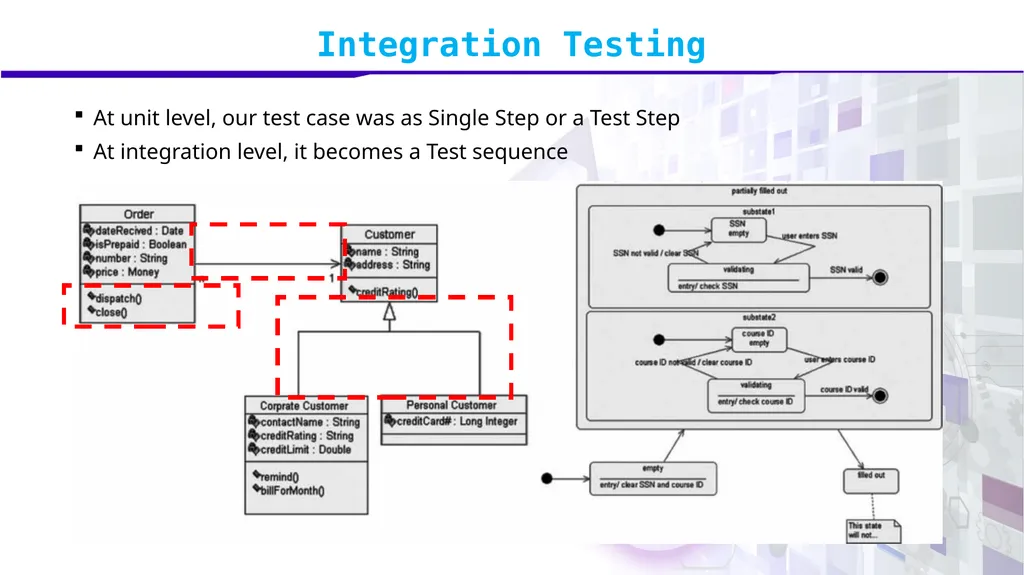
slide9. Integration Testing At unit level, our test case was as Single Step or a Test Step
At integration level, it becomes a Test sequence<br>
slide10. Integration Testing Imagine,
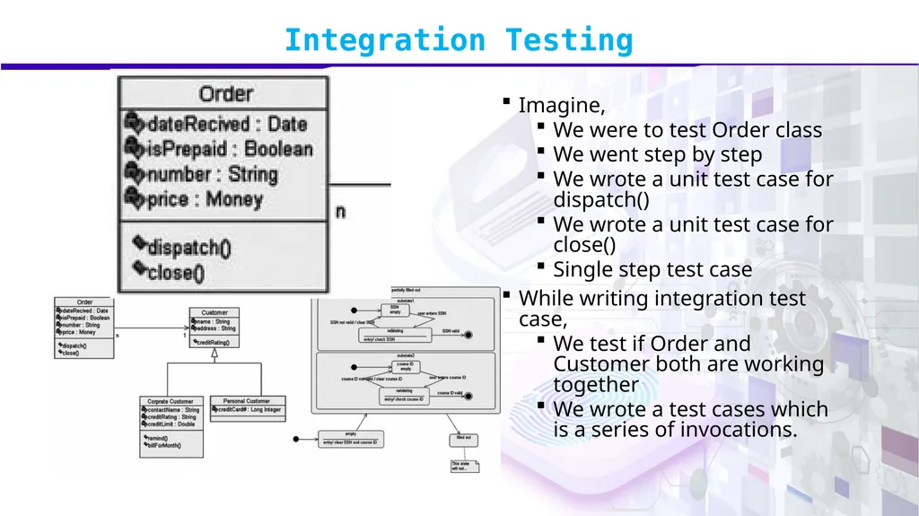
We were to test Order class
We went step by step
We wrote a unit test case for dispatch()
We wrote a unit test case for close()
Single step test case
While writing integration test case,
We test if Order and Customer both are working together
We wrote a test cases which is a series of invocations.<br>
slide11. Integration Testing While integration testing,
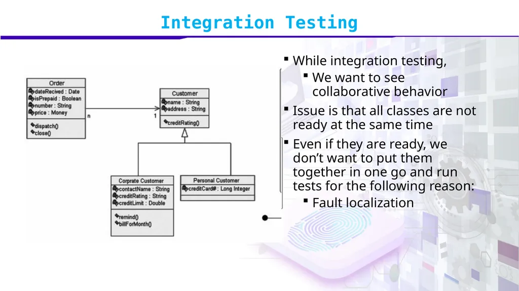
We want to see collaborative behavior
Issue is that all classes are not ready at the same time
Even if they are ready, we don’t want to put them together in one go and run tests for the following reason:
Fault localization<br>
slide12. Integration Testing Integration testing techniques
Functional Decomposition
applies best to procedural code
Call Graph
applies to both procedural and object-oriented code
MM-Paths
apply to both procedural and object-oriented code<br>
slide13. Module 48: Functional decomposition based Integration<br>
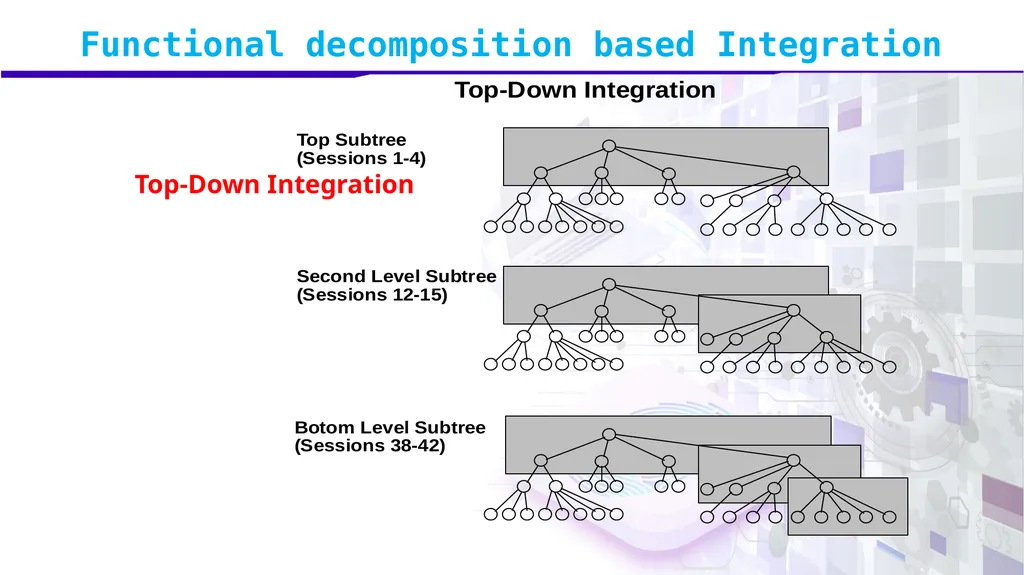
slide14. Integration Testing Top-down integration strategy
focuses on testing the top layer or the controlling subsystem first
i.e. the main, or the root of the call tree)
Sometimes, we have an early prototype ready
Sometimes required to build an understanding (both SE team and the client)
We then naturally follow top-down integration of system and test<br>
slide15. Integration Testing We gradually add more subsystems that are referenced/required by the already tested subsystems
Do this until all subsystems are incorporated into the test<br>
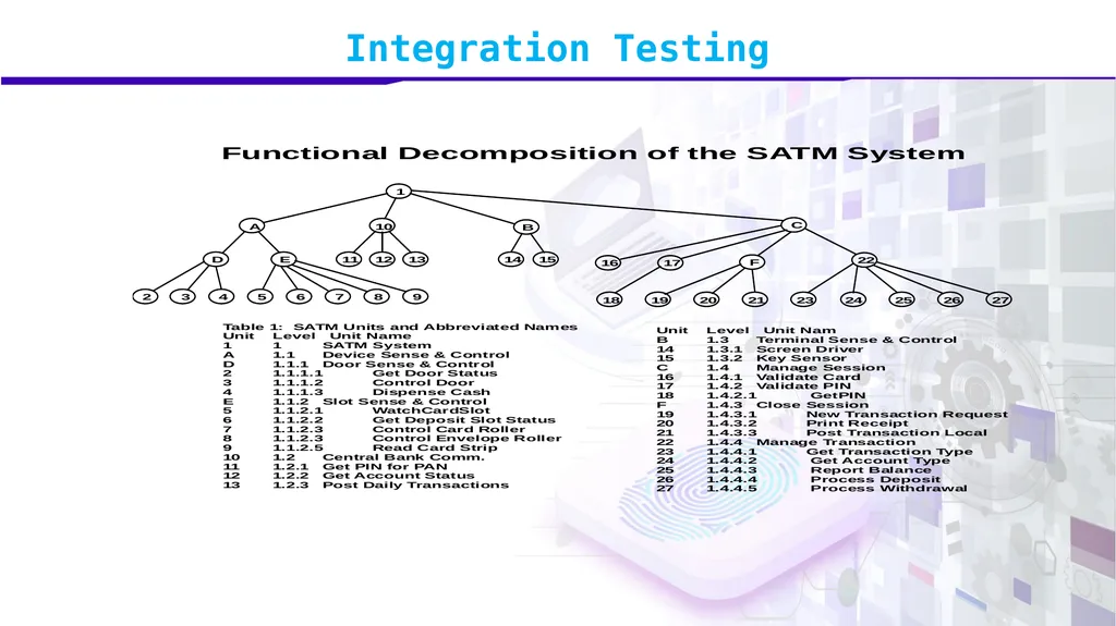
slide16. Integration Testing<br>
slide17. Functional decomposition based Integration Top-Down Integration<br>
slide18. Functional decomposition based Integration Issues:
Writing stubs can be difficult
when parameter passing is complex.
Stubs must allow all possible conditions to be tested
number of stubs required may become high,
In case lowest level of the system contains many functional units<br>
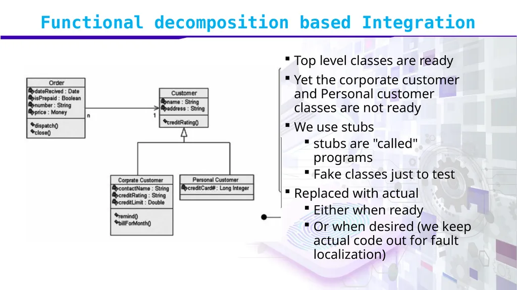
slide19. Functional decomposition based Integration Top level classes are ready
Yet the corporate customer and Personal customer classes are not ready
We use stubs
stubs are "called" programs
Fake classes just to test
Replaced with actual
Either when ready
Or when desired (we keep actual code out for fault localization)<br>
slide20. Functional decomposition based Integration Bottom-Up integration strategy
We do testing of units at the lowest levels first
Gradually include sub systems that reference / require previously tested subsystems
This is done repeatedly until all subsystems are included in the testing
Drivers required which is a “fake” routine that requires a subsystem and passes a test case to it<br>
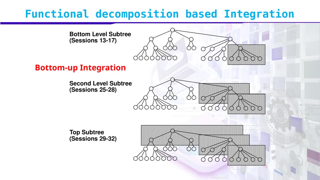
slide21. Functional decomposition based Integration Top Subtree (Sessions 29-32) Second Level Subtree (Sessions 25-28) Bottom Level Subtree (Sessions 13-17) Bottom-up Integration<br>
slide22. Functional decomposition based Integration Issues:
Not optimal strategy for functionally decomposed systems:
Tests the most important subsystem (UI) last
More useful for integrating object-oriented systems
Drivers may be more complicated than stubs
Less drivers than stubs are typically required<br>
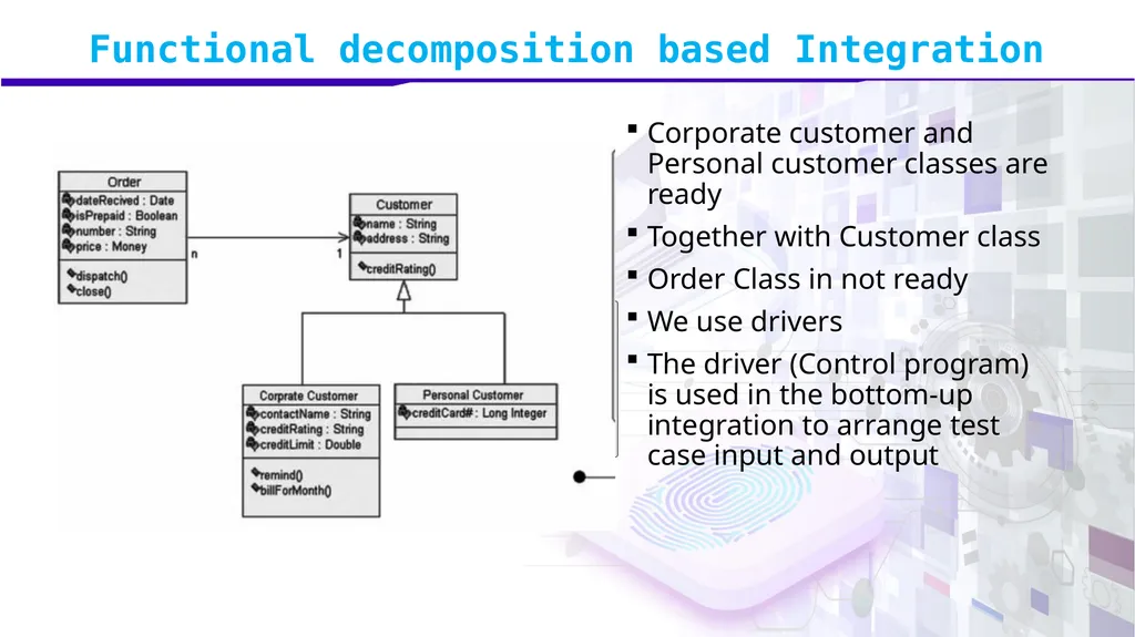
slide23. Functional decomposition based Integration Corporate customer and Personal customer classes are ready
Together with Customer class
Order Class in not ready
We use drivers
The driver (Control program) is used in the bottom-up integration to arrange test case input and output<br>
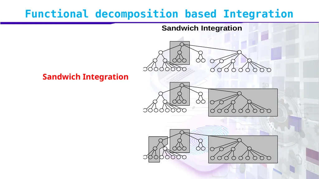
slide24. Functional decomposition based Integration Sandwich Integration
Combines top-down strategy with bottom-up strategy
Less stub and driver development effort
Added difficulty in fault isolation<br>
slide25. Functional decomposition based Integration Sandwich Integration<br>
slide26. Module 49: Call Graph based Integration<br>
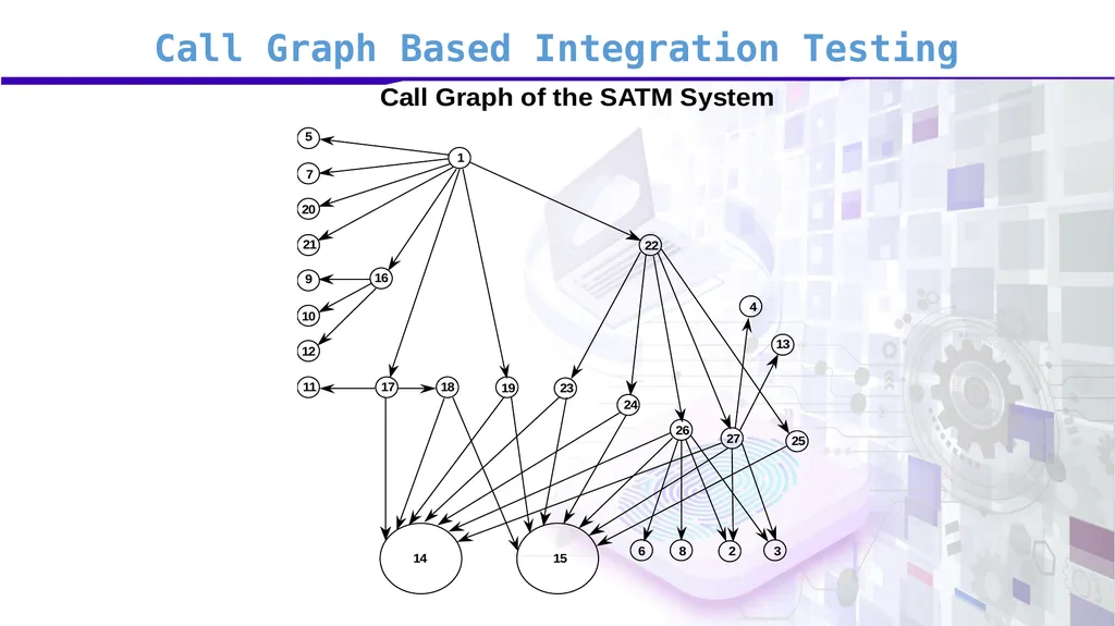
slide27. Call Graph Based Integration Testing Call Graph of a program is a directed graph in which
nodes are units
edges correspond to actual program calls (or messages)
Can still use the notions of stubs and drivers.
The basic idea is to use the call graph instead of the decomposition tree
Two sub-types
Pair-wise Integration
Neighborhood Integration<br>
slide28. Call Graph Based Integration Testing<br>
slide29. Call Graph Based Integration Testing By definition, and edge in the Call Graph refers to an interface between the units that are the endpoints of the edge.
Every edge represents a pair of units to test.
We want to test all edges are:
Essentially required
Meaningfully implemented<br>
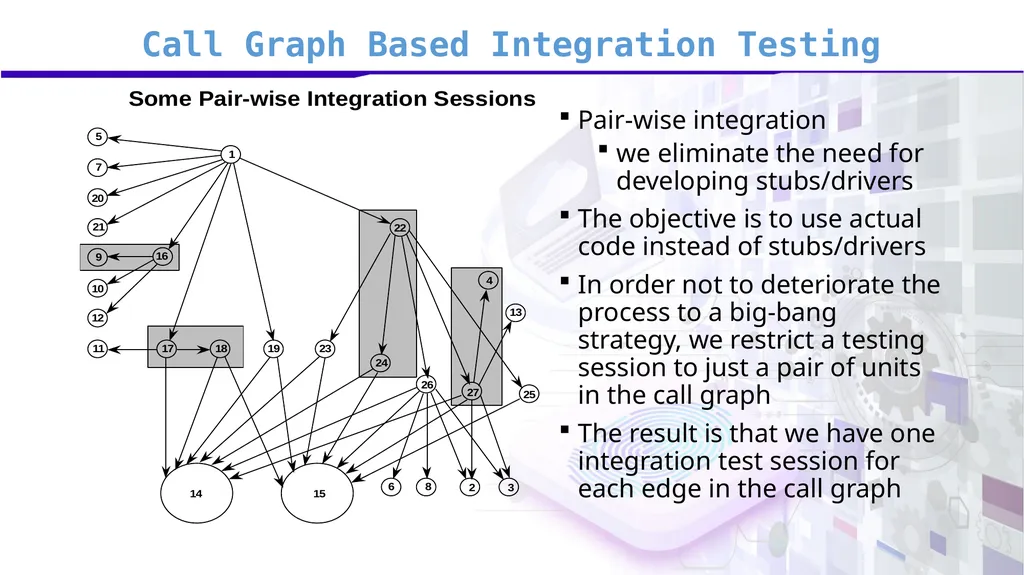
slide30. Call Graph Based Integration Testing Pair-wise integration
we eliminate the need for developing stubs/drivers
The objective is to use actual code instead of stubs/drivers
In order not to deteriorate the process to a big-bang strategy, we restrict a testing session to just a pair of units in the call graph
The result is that we have one integration test session for each edge in the call graph<br>
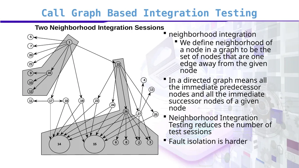
slide31. Call Graph Based Integration Testing neighborhood integration
We define neighborhood of a node in a graph to be the set of nodes that are one edge away from the given node
In a directed graph means all the immediate predecessor nodes and all the immediate successor nodes of a given node
Neighborhood Integration Testing reduces the number of test sessions
Fault isolation is harder<br>
slide32. Call Graph Based Integration Testing The neighborhood (or radius 1) of a node in a graph is the set of nodes that are one edge away from the given node.
This can be extended to larger sets by choosing larger values for the radius.
Stub and driver effort is reduced.<br>
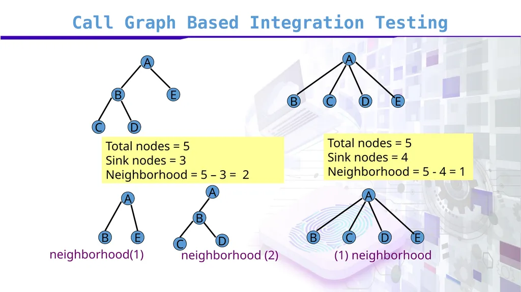
slide33. Call Graph Based Integration Testing A E B B A D C C D E Total nodes = 5
Sink nodes = 3
Neighborhood = 5 – 3 = 2 Total nodes = 5
Sink nodes = 4
Neighborhood = 5 - 4 = 1 A E A B D C B A C D E neighborhood(1) neighborhood (2) (1) neighborhood B<br>
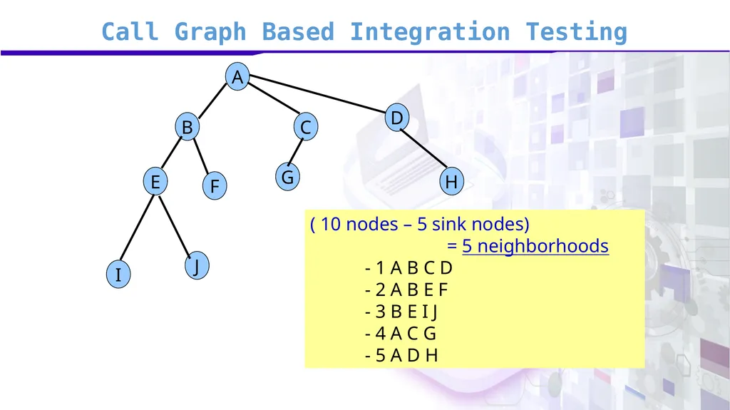
slide34. Call Graph Based Integration Testing A B C D I J F G H E ( 10 nodes – 5 sink nodes)
= 5 neighborhoods
- 1 A B C D
- 2 A B E F
- 3 B E I J
- 4 A C G
- 5 A D H<br>
slide35. Module 50: Path based Integration<br>
slide36. Path Based Integration The basic idea is to focus on interactions among system units rather than merely to test interfaces among separately developed and tested units
In this respect, interface-based testing is structural while interaction-based is behavioral (why?)
Overall we want to express integration testing in terms behavioral threads<br>
slide37. Path Based Integration Source node:
a program statement fragment at which program execution begins or resumes.
for example the first “begin” statement in a program.
also, immediately after nodes that transfer control to other units.
Sink node:
a statement fragment at which program execution terminates.
the final “end” in a program as well as statements that transfer control to other units.<br>
slide38. Path Based Integration Module execution path:
a sequence of statements that begins with a source node and ends with a sink node with no intervening sink nodes.
Message:
a programming language mechanism by which one unit transfers control to another unit.<br>
slide39. Path Based Integration Message:
can be interpreted as subroutine invocations, procedure calls and function references.
convention: the unit which receives the message always eventually returns control to the message source.
messages can pass data to other units.<br>
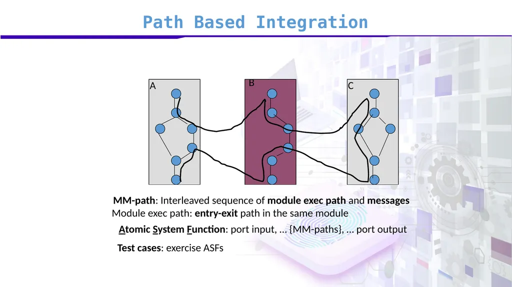
slide40. Path Based Integration MM-Path:
an interleaved sequence of module execution paths and messages.
we can describe sequences of module execution paths that include transfers of control among separate units.
MM-paths always represent feasible execution paths, and these paths cross unit boundaries.<br>
slide41. Path Based Integration There are three observable behavioral criteria that put endpoints on MM-Paths:
event quiescence: occurs when a system is nearly idle, waiting for a port input event to trigger further processing.
This is a system level property with an analog at the integration level: message quiescence.<br>
slide42. Path Based Integration message quiescence: occurs when a unit that sends no messages is reached (i.e. module C in Figure 1).
data quiescence: occurs when a sequence of processing culminates in the creation of stored data that is not immediately used.<br>
slide43. Path Based Integration Data quiescence occurs when a sequence of processing culminates in the creation of stored data that is not immediately used.
These criteria are “natural” endpoints for MM-Paths.<br>
slide44. Path Based Integration A second guideline for MM-Paths serves to distinguish integration from system testing:
atomic system function (ASF): is an action that is observable at the system level in terms of port input and output events.
It begins with a port input event,
traverses one or more MM-Paths,
and terminates with a port output event.<br>
slide45. Path Based Integration When viewed from the system level, there is no compelling reason to decompose an ASF into lower levels of detail (hence the atomicity).
For example in the ATM case,
an example of an ASF is card entry, cash dispensing, or session closing.
While PIN entry would probably be too big since it might entail a molecular system function<br>
slide46. Path Based Integration ASFs are an upper limit for MM-Paths:
MM-Paths should not cross ASF boundaries.
ASFs represent the seam between integration and system testing:
they are the largest item to be tested during integration testing,
and the smallest item for system testing.<br>
slide47. Path Based Integration A B C MM-path: Interleaved sequence of module exec path and messages Module exec path: entry-exit path in the same module Atomic System Function: port input, … {MM-paths}, … port output Test cases: exercise ASFs<br>
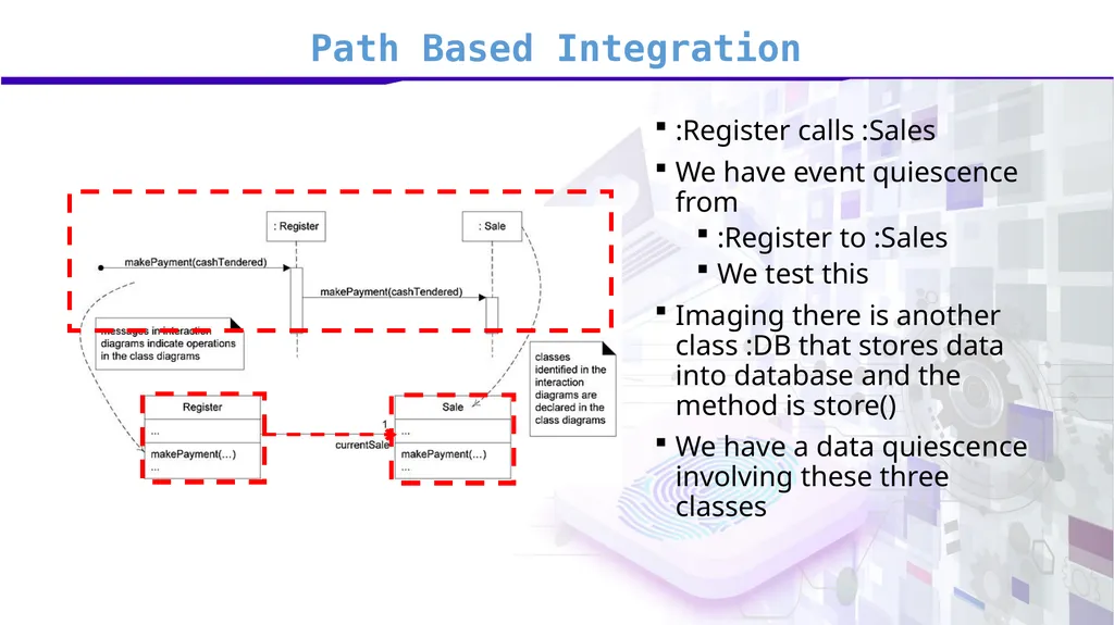
slide48. Path Based Integration :Register calls :Sales
We have event quiescence from
:Register to :Sales
We test this
Imaging there is another class :DB that stores data into database and the method is store()
We have a data quiescence involving these three classes<br>
slide49. We have covered:
Functional Decomposition
Call Graph
MM-Paths END<br>
slide2. Software Verification and Validation Agenda
Integration Testing
Functional decomposition based Integration
Call Graph based Integration
Path based Integration<br>
slide3. Module 47: Integration Testing<br>
slide4. Integration Testing While developing unit test strategy, we consider:
Test Requirement
Documentation requirement
Tools / Test utilities?
Individual units get combined into (sub-) modules
We need to assure if:
they are following design accurately
they are collaborating properly
We do integration testing<br>
slide5. Integration Testing Unit assumptions
All other units are correct
Compiles correctly
Integration assumptions
Unit testing complete
System assumptions
Integration testing complete
Tests occur at port boundary<br>
slide6. Integration Testing Unit goals
Correct unit function
Coverage metrics satisfied
Integration goals
Interfaces correct
Correct function across units
Fault isolation support
System goals
Correct system functions
Non-functional requirements tested
Customer satisfaction<br>
slide7. Integration Testing Imagine, developer X implemented and tested “Register” Class
Imagine, developer Y implemented and tested “Sales” Class<br>
slide8. Integration Testing Development manager wants to:
Test if individual units are working properly?
To verify if adequate testing at developer level was performed
NOT redoing the whole testing effort again
If units are collaborating as anticipated?<br>
slide9. Integration Testing At unit level, our test case was as Single Step or a Test Step
At integration level, it becomes a Test sequence<br>
slide10. Integration Testing Imagine,
We were to test Order class
We went step by step
We wrote a unit test case for dispatch()
We wrote a unit test case for close()
Single step test case
While writing integration test case,
We test if Order and Customer both are working together
We wrote a test cases which is a series of invocations.<br>
slide11. Integration Testing While integration testing,
We want to see collaborative behavior
Issue is that all classes are not ready at the same time
Even if they are ready, we don’t want to put them together in one go and run tests for the following reason:
Fault localization<br>
slide12. Integration Testing Integration testing techniques
Functional Decomposition
applies best to procedural code
Call Graph
applies to both procedural and object-oriented code
MM-Paths
apply to both procedural and object-oriented code<br>
slide13. Module 48: Functional decomposition based Integration<br>
slide14. Integration Testing Top-down integration strategy
focuses on testing the top layer or the controlling subsystem first
i.e. the main, or the root of the call tree)
Sometimes, we have an early prototype ready
Sometimes required to build an understanding (both SE team and the client)
We then naturally follow top-down integration of system and test<br>
slide15. Integration Testing We gradually add more subsystems that are referenced/required by the already tested subsystems
Do this until all subsystems are incorporated into the test<br>
slide16. Integration Testing<br>
slide17. Functional decomposition based Integration Top-Down Integration<br>
slide18. Functional decomposition based Integration Issues:
Writing stubs can be difficult
when parameter passing is complex.
Stubs must allow all possible conditions to be tested
number of stubs required may become high,
In case lowest level of the system contains many functional units<br>
slide19. Functional decomposition based Integration Top level classes are ready
Yet the corporate customer and Personal customer classes are not ready
We use stubs
stubs are "called" programs
Fake classes just to test
Replaced with actual
Either when ready
Or when desired (we keep actual code out for fault localization)<br>
slide20. Functional decomposition based Integration Bottom-Up integration strategy
We do testing of units at the lowest levels first
Gradually include sub systems that reference / require previously tested subsystems
This is done repeatedly until all subsystems are included in the testing
Drivers required which is a “fake” routine that requires a subsystem and passes a test case to it<br>
slide21. Functional decomposition based Integration Top Subtree (Sessions 29-32) Second Level Subtree (Sessions 25-28) Bottom Level Subtree (Sessions 13-17) Bottom-up Integration<br>
slide22. Functional decomposition based Integration Issues:
Not optimal strategy for functionally decomposed systems:
Tests the most important subsystem (UI) last
More useful for integrating object-oriented systems
Drivers may be more complicated than stubs
Less drivers than stubs are typically required<br>
slide23. Functional decomposition based Integration Corporate customer and Personal customer classes are ready
Together with Customer class
Order Class in not ready
We use drivers
The driver (Control program) is used in the bottom-up integration to arrange test case input and output<br>
slide24. Functional decomposition based Integration Sandwich Integration
Combines top-down strategy with bottom-up strategy
Less stub and driver development effort
Added difficulty in fault isolation<br>
slide25. Functional decomposition based Integration Sandwich Integration<br>
slide26. Module 49: Call Graph based Integration<br>
slide27. Call Graph Based Integration Testing Call Graph of a program is a directed graph in which
nodes are units
edges correspond to actual program calls (or messages)
Can still use the notions of stubs and drivers.
The basic idea is to use the call graph instead of the decomposition tree
Two sub-types
Pair-wise Integration
Neighborhood Integration<br>
slide28. Call Graph Based Integration Testing<br>
slide29. Call Graph Based Integration Testing By definition, and edge in the Call Graph refers to an interface between the units that are the endpoints of the edge.
Every edge represents a pair of units to test.
We want to test all edges are:
Essentially required
Meaningfully implemented<br>
slide30. Call Graph Based Integration Testing Pair-wise integration
we eliminate the need for developing stubs/drivers
The objective is to use actual code instead of stubs/drivers
In order not to deteriorate the process to a big-bang strategy, we restrict a testing session to just a pair of units in the call graph
The result is that we have one integration test session for each edge in the call graph<br>
slide31. Call Graph Based Integration Testing neighborhood integration
We define neighborhood of a node in a graph to be the set of nodes that are one edge away from the given node
In a directed graph means all the immediate predecessor nodes and all the immediate successor nodes of a given node
Neighborhood Integration Testing reduces the number of test sessions
Fault isolation is harder<br>
slide32. Call Graph Based Integration Testing The neighborhood (or radius 1) of a node in a graph is the set of nodes that are one edge away from the given node.
This can be extended to larger sets by choosing larger values for the radius.
Stub and driver effort is reduced.<br>
slide33. Call Graph Based Integration Testing A E B B A D C C D E Total nodes = 5
Sink nodes = 3
Neighborhood = 5 – 3 = 2 Total nodes = 5
Sink nodes = 4
Neighborhood = 5 - 4 = 1 A E A B D C B A C D E neighborhood(1) neighborhood (2) (1) neighborhood B<br>
slide34. Call Graph Based Integration Testing A B C D I J F G H E ( 10 nodes – 5 sink nodes)
= 5 neighborhoods
- 1 A B C D
- 2 A B E F
- 3 B E I J
- 4 A C G
- 5 A D H<br>
slide35. Module 50: Path based Integration<br>
slide36. Path Based Integration The basic idea is to focus on interactions among system units rather than merely to test interfaces among separately developed and tested units
In this respect, interface-based testing is structural while interaction-based is behavioral (why?)
Overall we want to express integration testing in terms behavioral threads<br>
slide37. Path Based Integration Source node:
a program statement fragment at which program execution begins or resumes.
for example the first “begin” statement in a program.
also, immediately after nodes that transfer control to other units.
Sink node:
a statement fragment at which program execution terminates.
the final “end” in a program as well as statements that transfer control to other units.<br>
slide38. Path Based Integration Module execution path:
a sequence of statements that begins with a source node and ends with a sink node with no intervening sink nodes.
Message:
a programming language mechanism by which one unit transfers control to another unit.<br>
slide39. Path Based Integration Message:
can be interpreted as subroutine invocations, procedure calls and function references.
convention: the unit which receives the message always eventually returns control to the message source.
messages can pass data to other units.<br>
slide40. Path Based Integration MM-Path:
an interleaved sequence of module execution paths and messages.
we can describe sequences of module execution paths that include transfers of control among separate units.
MM-paths always represent feasible execution paths, and these paths cross unit boundaries.<br>
slide41. Path Based Integration There are three observable behavioral criteria that put endpoints on MM-Paths:
event quiescence: occurs when a system is nearly idle, waiting for a port input event to trigger further processing.
This is a system level property with an analog at the integration level: message quiescence.<br>
slide42. Path Based Integration message quiescence: occurs when a unit that sends no messages is reached (i.e. module C in Figure 1).
data quiescence: occurs when a sequence of processing culminates in the creation of stored data that is not immediately used.<br>
slide43. Path Based Integration Data quiescence occurs when a sequence of processing culminates in the creation of stored data that is not immediately used.
These criteria are “natural” endpoints for MM-Paths.<br>
slide44. Path Based Integration A second guideline for MM-Paths serves to distinguish integration from system testing:
atomic system function (ASF): is an action that is observable at the system level in terms of port input and output events.
It begins with a port input event,
traverses one or more MM-Paths,
and terminates with a port output event.<br>
slide45. Path Based Integration When viewed from the system level, there is no compelling reason to decompose an ASF into lower levels of detail (hence the atomicity).
For example in the ATM case,
an example of an ASF is card entry, cash dispensing, or session closing.
While PIN entry would probably be too big since it might entail a molecular system function<br>
slide46. Path Based Integration ASFs are an upper limit for MM-Paths:
MM-Paths should not cross ASF boundaries.
ASFs represent the seam between integration and system testing:
they are the largest item to be tested during integration testing,
and the smallest item for system testing.<br>
slide47. Path Based Integration A B C MM-path: Interleaved sequence of module exec path and messages Module exec path: entry-exit path in the same module Atomic System Function: port input, … {MM-paths}, … port output Test cases: exercise ASFs<br>
slide48. Path Based Integration :Register calls :Sales
We have event quiescence from
:Register to :Sales
We test this
Imaging there is another class :DB that stores data into database and the method is store()
We have a data quiescence involving these three classes<br>
slide49. We have covered:
Functional Decomposition
Call Graph
MM-Paths END<br>