
Tyre Abrasion Test Convoy Method –
Description: Tyre Abrasion Test Convoy Method Dual-Normalisation Framework Integrated Intra-Circuit Inter-Circuit Harmonization Physics-Aligned Governance-Ready Methodology ITTAC Proposal Objective Improve intra-circuit reliability inter-circuit
Related Topics
Download Presentation
"Tyre Abrasion Test Convoy Method –" is the property of its rightful owner. Permission is granted to download and print the materials on this website for personal, non-commercial use only, and to display it on your personal computer provided you do not modify the materials and that you retain all copyright notices contained in the materials. By downloading content from our website, you accept the terms of this agreement.
Presentation Transcript
slide1. Tyre Abrasion Test
Convoy Method – Dual-Normalisation Framework Integrated Intra-Circuit & Inter-Circuit Harmonization
Physics-Aligned & Governance-Ready Methodology ITTAC Proposal<br>
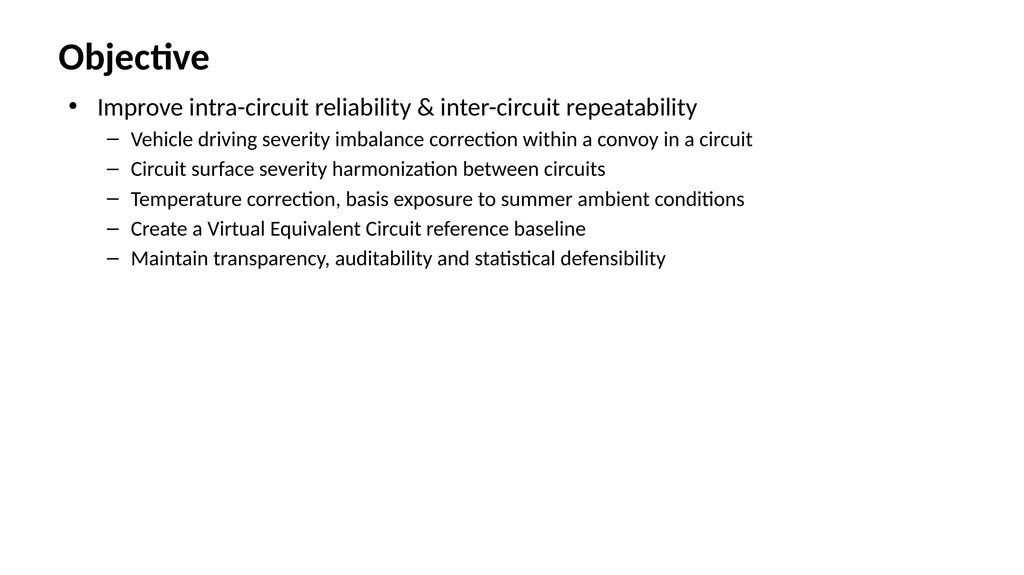
slide2. Objective Improve intra-circuit reliability & inter-circuit repeatability
Vehicle driving severity imbalance correction within a convoy in a circuit
Circuit surface severity harmonization between circuits
Temperature correction, basis exposure to summer ambient conditions
Create a Virtual Equivalent Circuit reference baseline
Maintain transparency, auditability and statistical defensibility<br>
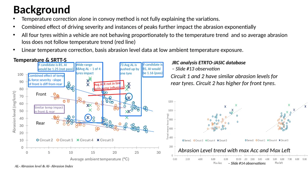
slide3. Background Wide range
68Avg AL – 1 of 4 tyres impact 73 Avg AL is pushed up by one tyre If candidate is 85, AI would be 1.25 (not pass) If candidate is 85, AI would be 1.16 (pass) Similar temp impact in front & rear Combined effect of temp & force severity –slope of front is diff from rear Temperature & SRTT-S Temperature correction alone in convoy method is not fully explaining the variations.
Combined effect of driving severity and instances of peaks further impact the abrasion exponentially
All four tyres within a vehicle are not behaving proportionately to the temperature trend and so average abrasion loss does not follow temperature trend (red line)
Linear temperature correction, basis abrasion level data at low ambient temperature exposure. JRC analysis ETRTO-JASIC database
– Slide #13 observation Circuit 1 and 2 have similar abrasion levels for rear tyres. Circuit 2 has higher for front tyres. Avg ALR not in line with temp influence AL- Abrasion level & AI- Abrasion Index<br>
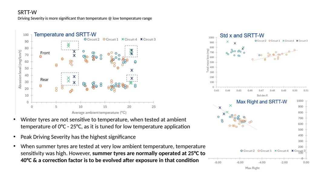
slide4. SRTT-W Driving Severity is more significant than temperature @ low temperature range Peak Driving Severity has the highest significance Winter tyres are not sensitive to temperature, when tested at ambient temperature of 0°C - 25°C, as it is tuned for low temperature application When summer tyres are tested at very low ambient temperature, temperature sensitivity was high. However, summer tyres are normally operated at 25°C to 40°C & a correction factor is to be evolved after exposure in that condition<br>
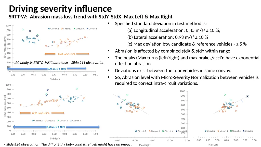
slide5. Driving severity influence SRTT-W: Abrasion mass loss trend with StdY, StdX, Max Left & Max Right The diff of Std Y betw cand & ref veh might have an impact. – Slide #24 observation Specified standard deviation in test method is:
(a) Longitudinal acceleration: 0.45 m/s2 ± 10 %;
(b) Lateral acceleration: 0.93 m/s2 ± 10 %
(c) Max deviation btw candidate & reference vehicles - ± 5 %
Abrasion is affected by combined stdX & stdY within range
The peaks (Max turns (left/right) and max brakes/accl’n have exponential effect on abrasion
Deviations exist between the four vehicles in same convoy.
So, Abrasion level with Micro-Severity Normalization between vehicles is required to correct intra-circuit variations.<br>
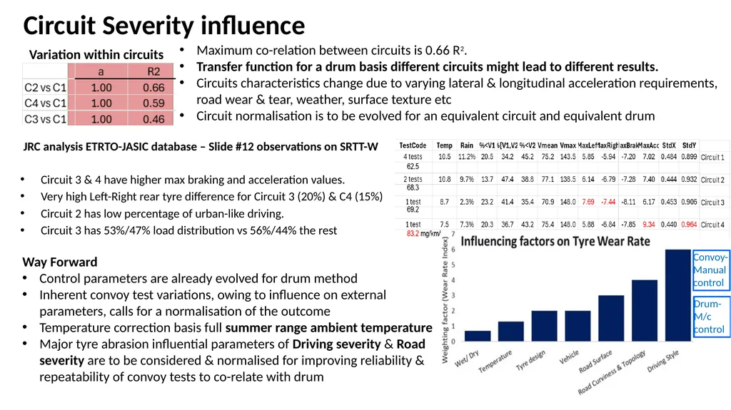
slide6. Circuit Severity influence Convoy- Manual control Drum- M/c control Circuit 3 & 4 have higher max braking and acceleration values.
Very high Left-Right rear tyre difference for Circuit 3 (20%) & C4 (15%)
Circuit 2 has low percentage of urban-like driving.
Circuit 3 has 53%/47% load distribution vs 56%/44% the rest JRC analysis ETRTO-JASIC database – Slide #12 observations on SRTT-W Maximum co-relation between circuits is 0.66 R2.
Transfer function for a drum basis different circuits might lead to different results.
Circuits characteristics change due to varying lateral & longitudinal acceleration requirements, road wear & tear, weather, surface texture etc
Circuit normalisation is to be evolved for an equivalent circuit and equivalent drum Variation within circuits Way Forward
Control parameters are already evolved for drum method
Inherent convoy test variations, owing to influence on external parameters, calls for a normalisation of the outcome
Temperature correction basis full summer range ambient temperature
Major tyre abrasion influential parameters of Driving severity & Road severity are to be considered & normalised for improving reliability & repeatability of convoy tests to co-relate with drum<br>
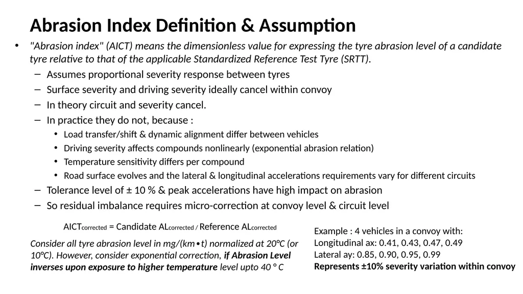
slide7. Abrasion Index Definition & Assumption "Abrasion index" (AICT) means the dimensionless value for expressing the tyre abrasion level of a candidate tyre relative to that of the applicable Standardized Reference Test Tyre (SRTT).
Assumes proportional severity response between tyres
Surface severity and driving severity ideally cancel within convoy
In theory circuit and severity cancel.
In practice they do not, because :
Load transfer/shift & dynamic alignment differ between vehicles
Driving severity affects compounds nonlinearly (exponential abrasion relation)
Temperature sensitivity differs per compound
Road surface evolves and the lateral & longitudinal accelerations requirements vary for different circuits
Tolerance level of ± 10 % & peak accelerations have high impact on abrasion
So residual imbalance requires micro-correction at convoy level & circuit level Example : 4 vehicles in a convoy with:
Longitudinal ax: 0.41, 0.43, 0.47, 0.49
Lateral ay: 0.85, 0.90, 0.95, 0.99
Represents ±10% severity variation within convoy AICTcorrected = Candidate ALcorrected / Reference ALcorrected Consider all tyre abrasion level in mg/(km∙t) normalized at 20°C (or 10°C). However, consider exponential correction, if Abrasion Level inverses upon exposure to higher temperature level upto 40 ° C<br>
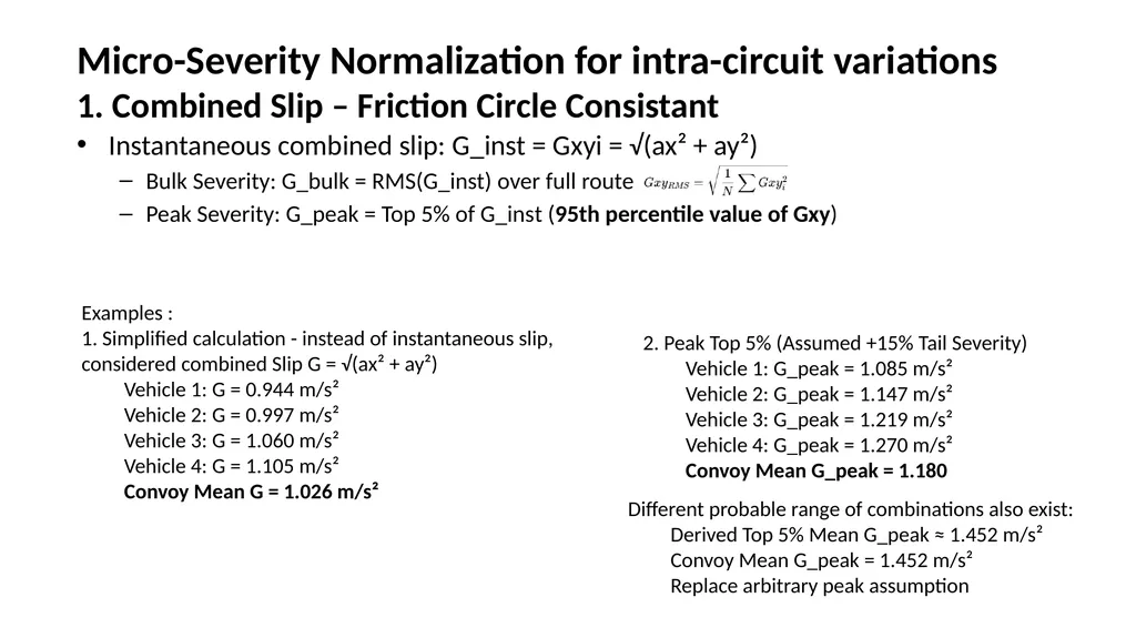
slide8. Micro-Severity Normalization for intra-circuit variations 1. Combined Slip – Friction Circle Consistant Instantaneous combined slip: G_inst = Gxyi = √(ax² + ay²)
Bulk Severity: G_bulk = RMS(G_inst) over full route
Peak Severity: G_peak = Top 5% of G_inst (95th percentile value of Gxy) Examples :
1. Simplified calculation - instead of instantaneous slip, considered combined Slip G = √(ax² + ay²)
Vehicle 1: G = 0.944 m/s²
Vehicle 2: G = 0.997 m/s²
Vehicle 3: G = 1.060 m/s²
Vehicle 4: G = 1.105 m/s²
Convoy Mean G = 1.026 m/s² 2. Peak Top 5% (Assumed +15% Tail Severity)
Vehicle 1: G_peak = 1.085 m/s²
Vehicle 2: G_peak = 1.147 m/s²
Vehicle 3: G_peak = 1.219 m/s²
Vehicle 4: G_peak = 1.270 m/s²
Convoy Mean G_peak = 1.180 Different probable range of combinations also exist:
Derived Top 5% Mean G_peak ≈ 1.452 m/s²
Convoy Mean G_peak = 1.452 m/s²
Replace arbitrary peak assumption<br>
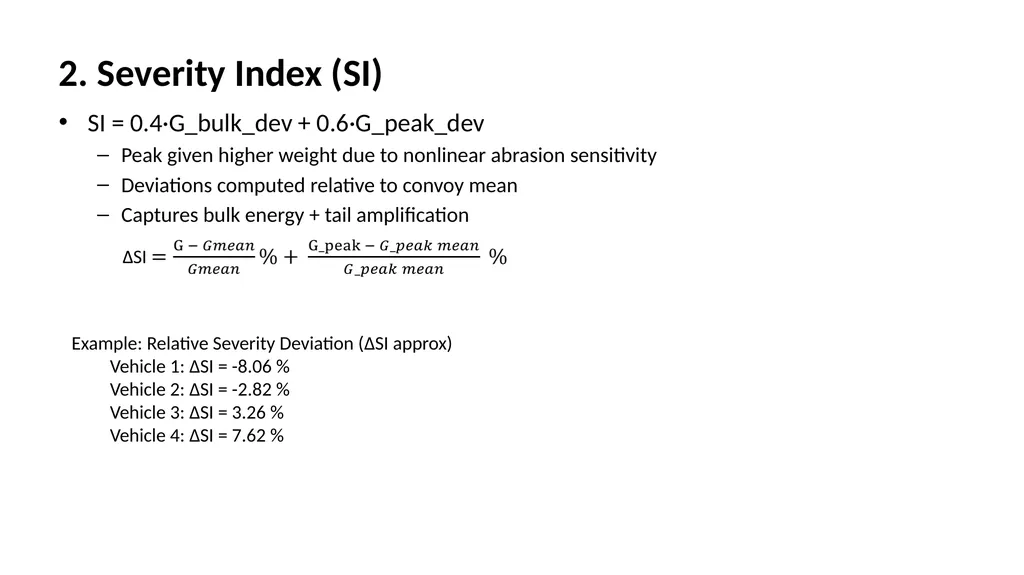
slide9. 2. Severity Index (SI) SI = 0.4·G_bulk_dev + 0.6·G_peak_dev
Peak given higher weight due to nonlinear abrasion sensitivity
Deviations computed relative to convoy mean
Captures bulk energy + tail amplification Example: Relative Severity Deviation (ΔSI approx)
Vehicle 1: ΔSI = -8.06 %
Vehicle 2: ΔSI = -2.82 %
Vehicle 3: ΔSI = 3.26 %
Vehicle 4: ΔSI = 7.62 %<br>
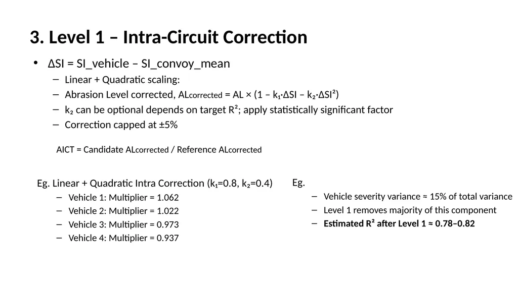
slide10. 3. Level 1 – Intra-Circuit Correction ΔSI = SI_vehicle – SI_convoy_mean
Linear + Quadratic scaling:
Abrasion Level corrected, ALcorrected = AL × (1 – k₁·ΔSI – k₂·ΔSI²)
k₂ can be optional depends on target R²; apply statistically significant factor
Correction capped at ±5% Eg. Linear + Quadratic Intra Correction (k₁=0.8, k₂=0.4)
Vehicle 1: Multiplier = 1.062
Vehicle 2: Multiplier = 1.022
Vehicle 3: Multiplier = 0.973
Vehicle 4: Multiplier = 0.937 Eg.
Vehicle severity variance ≈ 15% of total variance
Level 1 removes majority of this component
Estimated R² after Level 1 ≈ 0.78–0.82 AICT = Candidate ALcorrected / Reference ALcorrected<br>
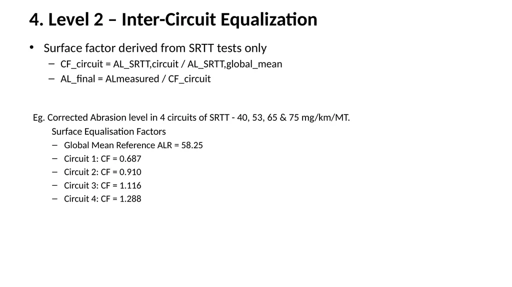
slide11. 4. Level 2 – Inter-Circuit Equalization Surface factor derived from SRTT tests only
CF_circuit = AL_SRTT,circuit / AL_SRTT,global_mean
AL_final = ALmeasured / CF_circuit Eg. Corrected Abrasion level in 4 circuits of SRTT - 40, 53, 65 & 75 mg/km/MT.
Surface Equalisation Factors
Global Mean Reference ALR = 58.25
Circuit 1: CF = 0.687
Circuit 2: CF = 0.910
Circuit 3: CF = 1.116
Circuit 4: CF = 1.288<br>
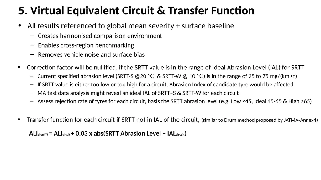
slide12. 5. Virtual Equivalent Circuit & Transfer Function All results referenced to global mean severity + surface baseline
Creates harmonised comparison environment
Enables cross-region benchmarking
Removes vehicle noise and surface bias Correction factor will be nullified, if the SRTT value is in the range of Ideal Abrasion Level (IAL) for SRTT
Current specified abrasion level (SRTT-S @20 ℃ & SRTT-W @ 10 ℃) is in the range of 25 to 75 mg/(km∙t)
If SRTT value is either too low or too high for a circuit, Abrasion Index of candidate tyre would be affected
MA test data analysis might reveal an ideal IAL of SRTT–S & SRTT-W for each circuit
Assess rejection rate of tyres for each circuit, basis the SRTT abrasion level (e.g. Low <45, Ideal 45-65 & High >65)
Transfer function for each circuit if SRTT not in IAL of the circuit, (similar to Drum method proposed by JATMA-Annex4) ALIcircuitTF = ALIcircuit + 0.03 x abs(SRTT Abrasion Level – IALcircuit)<br>
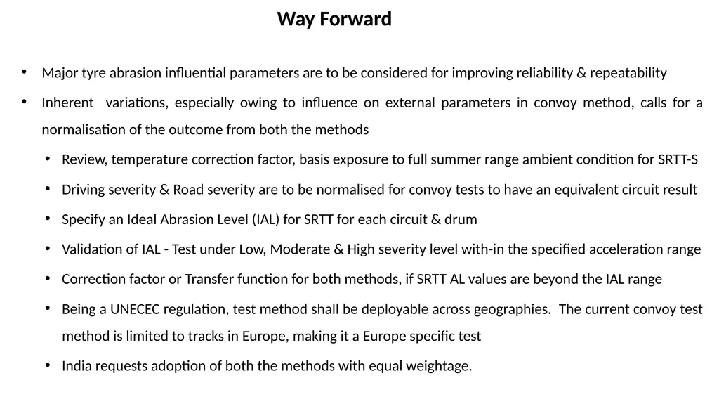
slide13. Way Forward Major tyre abrasion influential parameters are to be considered for improving reliability & repeatability
Inherent variations, especially owing to influence on external parameters in convoy method, calls for a normalisation of the outcome from both the methods
Review, temperature correction factor, basis exposure to full summer range ambient condition for SRTT-S
Driving severity & Road severity are to be normalised for convoy tests to have an equivalent circuit result
Specify an Ideal Abrasion Level (IAL) for SRTT for each circuit & drum
Validation of IAL - Test under Low, Moderate & High severity level with-in the specified acceleration range
Correction factor or Transfer function for both methods, if SRTT AL values are beyond the IAL range
Being a UNECEC regulation, test method shall be deployable across geographies. The current convoy test method is limited to tracks in Europe, making it a Europe specific test
India requests adoption of both the methods with equal weightage.<br>
Physics-Aligned & Governance-Ready Methodology ITTAC Proposal<br>
slide2. Objective Improve intra-circuit reliability & inter-circuit repeatability
Vehicle driving severity imbalance correction within a convoy in a circuit
Circuit surface severity harmonization between circuits
Temperature correction, basis exposure to summer ambient conditions
Create a Virtual Equivalent Circuit reference baseline
Maintain transparency, auditability and statistical defensibility<br>
slide3. Background Wide range
68Avg AL – 1 of 4 tyres impact 73 Avg AL is pushed up by one tyre If candidate is 85, AI would be 1.25 (not pass) If candidate is 85, AI would be 1.16 (pass) Similar temp impact in front & rear Combined effect of temp & force severity –slope of front is diff from rear Temperature & SRTT-S Temperature correction alone in convoy method is not fully explaining the variations.
Combined effect of driving severity and instances of peaks further impact the abrasion exponentially
All four tyres within a vehicle are not behaving proportionately to the temperature trend and so average abrasion loss does not follow temperature trend (red line)
Linear temperature correction, basis abrasion level data at low ambient temperature exposure. JRC analysis ETRTO-JASIC database
– Slide #13 observation Circuit 1 and 2 have similar abrasion levels for rear tyres. Circuit 2 has higher for front tyres. Avg ALR not in line with temp influence AL- Abrasion level & AI- Abrasion Index<br>
slide4. SRTT-W Driving Severity is more significant than temperature @ low temperature range Peak Driving Severity has the highest significance Winter tyres are not sensitive to temperature, when tested at ambient temperature of 0°C - 25°C, as it is tuned for low temperature application When summer tyres are tested at very low ambient temperature, temperature sensitivity was high. However, summer tyres are normally operated at 25°C to 40°C & a correction factor is to be evolved after exposure in that condition<br>
slide5. Driving severity influence SRTT-W: Abrasion mass loss trend with StdY, StdX, Max Left & Max Right The diff of Std Y betw cand & ref veh might have an impact. – Slide #24 observation Specified standard deviation in test method is:
(a) Longitudinal acceleration: 0.45 m/s2 ± 10 %;
(b) Lateral acceleration: 0.93 m/s2 ± 10 %
(c) Max deviation btw candidate & reference vehicles - ± 5 %
Abrasion is affected by combined stdX & stdY within range
The peaks (Max turns (left/right) and max brakes/accl’n have exponential effect on abrasion
Deviations exist between the four vehicles in same convoy.
So, Abrasion level with Micro-Severity Normalization between vehicles is required to correct intra-circuit variations.<br>
slide6. Circuit Severity influence Convoy- Manual control Drum- M/c control Circuit 3 & 4 have higher max braking and acceleration values.
Very high Left-Right rear tyre difference for Circuit 3 (20%) & C4 (15%)
Circuit 2 has low percentage of urban-like driving.
Circuit 3 has 53%/47% load distribution vs 56%/44% the rest JRC analysis ETRTO-JASIC database – Slide #12 observations on SRTT-W Maximum co-relation between circuits is 0.66 R2.
Transfer function for a drum basis different circuits might lead to different results.
Circuits characteristics change due to varying lateral & longitudinal acceleration requirements, road wear & tear, weather, surface texture etc
Circuit normalisation is to be evolved for an equivalent circuit and equivalent drum Variation within circuits Way Forward
Control parameters are already evolved for drum method
Inherent convoy test variations, owing to influence on external parameters, calls for a normalisation of the outcome
Temperature correction basis full summer range ambient temperature
Major tyre abrasion influential parameters of Driving severity & Road severity are to be considered & normalised for improving reliability & repeatability of convoy tests to co-relate with drum<br>
slide7. Abrasion Index Definition & Assumption "Abrasion index" (AICT) means the dimensionless value for expressing the tyre abrasion level of a candidate tyre relative to that of the applicable Standardized Reference Test Tyre (SRTT).
Assumes proportional severity response between tyres
Surface severity and driving severity ideally cancel within convoy
In theory circuit and severity cancel.
In practice they do not, because :
Load transfer/shift & dynamic alignment differ between vehicles
Driving severity affects compounds nonlinearly (exponential abrasion relation)
Temperature sensitivity differs per compound
Road surface evolves and the lateral & longitudinal accelerations requirements vary for different circuits
Tolerance level of ± 10 % & peak accelerations have high impact on abrasion
So residual imbalance requires micro-correction at convoy level & circuit level Example : 4 vehicles in a convoy with:
Longitudinal ax: 0.41, 0.43, 0.47, 0.49
Lateral ay: 0.85, 0.90, 0.95, 0.99
Represents ±10% severity variation within convoy AICTcorrected = Candidate ALcorrected / Reference ALcorrected Consider all tyre abrasion level in mg/(km∙t) normalized at 20°C (or 10°C). However, consider exponential correction, if Abrasion Level inverses upon exposure to higher temperature level upto 40 ° C<br>
slide8. Micro-Severity Normalization for intra-circuit variations 1. Combined Slip – Friction Circle Consistant Instantaneous combined slip: G_inst = Gxyi = √(ax² + ay²)
Bulk Severity: G_bulk = RMS(G_inst) over full route
Peak Severity: G_peak = Top 5% of G_inst (95th percentile value of Gxy) Examples :
1. Simplified calculation - instead of instantaneous slip, considered combined Slip G = √(ax² + ay²)
Vehicle 1: G = 0.944 m/s²
Vehicle 2: G = 0.997 m/s²
Vehicle 3: G = 1.060 m/s²
Vehicle 4: G = 1.105 m/s²
Convoy Mean G = 1.026 m/s² 2. Peak Top 5% (Assumed +15% Tail Severity)
Vehicle 1: G_peak = 1.085 m/s²
Vehicle 2: G_peak = 1.147 m/s²
Vehicle 3: G_peak = 1.219 m/s²
Vehicle 4: G_peak = 1.270 m/s²
Convoy Mean G_peak = 1.180 Different probable range of combinations also exist:
Derived Top 5% Mean G_peak ≈ 1.452 m/s²
Convoy Mean G_peak = 1.452 m/s²
Replace arbitrary peak assumption<br>
slide9. 2. Severity Index (SI) SI = 0.4·G_bulk_dev + 0.6·G_peak_dev
Peak given higher weight due to nonlinear abrasion sensitivity
Deviations computed relative to convoy mean
Captures bulk energy + tail amplification Example: Relative Severity Deviation (ΔSI approx)
Vehicle 1: ΔSI = -8.06 %
Vehicle 2: ΔSI = -2.82 %
Vehicle 3: ΔSI = 3.26 %
Vehicle 4: ΔSI = 7.62 %<br>
slide10. 3. Level 1 – Intra-Circuit Correction ΔSI = SI_vehicle – SI_convoy_mean
Linear + Quadratic scaling:
Abrasion Level corrected, ALcorrected = AL × (1 – k₁·ΔSI – k₂·ΔSI²)
k₂ can be optional depends on target R²; apply statistically significant factor
Correction capped at ±5% Eg. Linear + Quadratic Intra Correction (k₁=0.8, k₂=0.4)
Vehicle 1: Multiplier = 1.062
Vehicle 2: Multiplier = 1.022
Vehicle 3: Multiplier = 0.973
Vehicle 4: Multiplier = 0.937 Eg.
Vehicle severity variance ≈ 15% of total variance
Level 1 removes majority of this component
Estimated R² after Level 1 ≈ 0.78–0.82 AICT = Candidate ALcorrected / Reference ALcorrected<br>
slide11. 4. Level 2 – Inter-Circuit Equalization Surface factor derived from SRTT tests only
CF_circuit = AL_SRTT,circuit / AL_SRTT,global_mean
AL_final = ALmeasured / CF_circuit Eg. Corrected Abrasion level in 4 circuits of SRTT - 40, 53, 65 & 75 mg/km/MT.
Surface Equalisation Factors
Global Mean Reference ALR = 58.25
Circuit 1: CF = 0.687
Circuit 2: CF = 0.910
Circuit 3: CF = 1.116
Circuit 4: CF = 1.288<br>
slide12. 5. Virtual Equivalent Circuit & Transfer Function All results referenced to global mean severity + surface baseline
Creates harmonised comparison environment
Enables cross-region benchmarking
Removes vehicle noise and surface bias Correction factor will be nullified, if the SRTT value is in the range of Ideal Abrasion Level (IAL) for SRTT
Current specified abrasion level (SRTT-S @20 ℃ & SRTT-W @ 10 ℃) is in the range of 25 to 75 mg/(km∙t)
If SRTT value is either too low or too high for a circuit, Abrasion Index of candidate tyre would be affected
MA test data analysis might reveal an ideal IAL of SRTT–S & SRTT-W for each circuit
Assess rejection rate of tyres for each circuit, basis the SRTT abrasion level (e.g. Low <45, Ideal 45-65 & High >65)
Transfer function for each circuit if SRTT not in IAL of the circuit, (similar to Drum method proposed by JATMA-Annex4) ALIcircuitTF = ALIcircuit + 0.03 x abs(SRTT Abrasion Level – IALcircuit)<br>
slide13. Way Forward Major tyre abrasion influential parameters are to be considered for improving reliability & repeatability
Inherent variations, especially owing to influence on external parameters in convoy method, calls for a normalisation of the outcome from both the methods
Review, temperature correction factor, basis exposure to full summer range ambient condition for SRTT-S
Driving severity & Road severity are to be normalised for convoy tests to have an equivalent circuit result
Specify an Ideal Abrasion Level (IAL) for SRTT for each circuit & drum
Validation of IAL - Test under Low, Moderate & High severity level with-in the specified acceleration range
Correction factor or Transfer function for both methods, if SRTT AL values are beyond the IAL range
Being a UNECEC regulation, test method shall be deployable across geographies. The current convoy test method is limited to tracks in Europe, making it a Europe specific test
India requests adoption of both the methods with equal weightage.<br>