
Weighbridge Training Course Beijing - September






Description: Weighbridge Training Course Beijing - September 2017 Eccentricity Test Eccentricity - Determining the load to apply Non- Substitution method Instruments with a load receptor with four points of support or less Establish if the instrument
Related Topics
Download Presentation
"Weighbridge Training Course Beijing - September" is the property of its rightful owner. Permission is granted to download and print the materials on this website for personal, non-commercial use only, and to display it on your personal computer provided you do not modify the materials and that you retain all copyright notices contained in the materials. By downloading content from our website, you accept the terms of this agreement.
Presentation Transcript
slide1. Weighbridge Training Course
Beijing - September 2017 Eccentricity Test<br>
slide2. Eccentricity - Determining the load to apply Non- Substitution method
Instruments with a load receptor with four points of support or less
Establish if the instrument has four or less support points. If the instrument complies with this condition then the test load is equal to one third of the maximum capacity, plus the corresponding maximum value of any additive tare .
This load must be distributed in an area approximately equal to one-quarter of the surface area of the load receptor.<br>
slide3. Instruments with ≤ 4 points of support (cont’d) Large weights should be used in preference to several small weights. Smaller weights shall be placed on top of larger weights, but unnecessary stacking should be avoided within the segment to be tested.
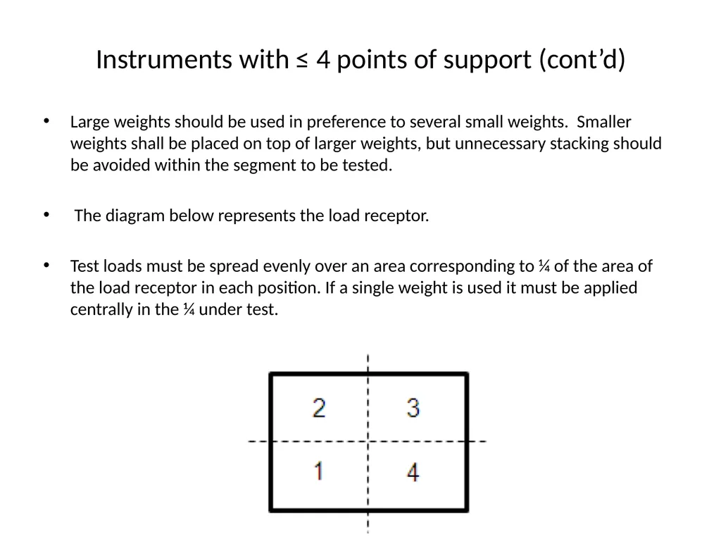
The diagram below represents the load receptor.
Test loads must be spread evenly over an area corresponding to ¼ of the area of the load receptor in each position. If a single weight is used it must be applied centrally in the ¼ under test.<br>
slide4. Instruments with ≤ 4 points of support (cont’d) Zero the instrument under test.
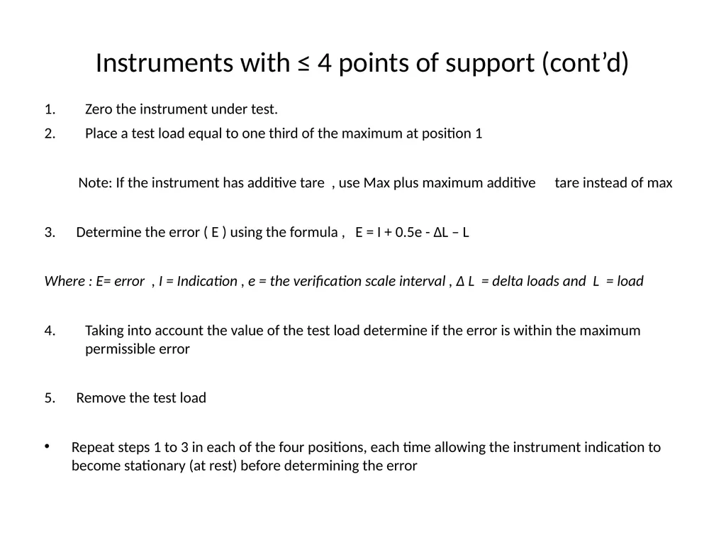
Place a test load equal to one third of the maximum at position 1
Note: If the instrument has additive tare , use Max plus maximum additive tare instead of max
3. Determine the error ( E ) using the formula , E = I + 0.5e - ∆L – L
Where : E= error , I = Indication , e = the verification scale interval , ∆ L = delta loads and L = load
Taking into account the value of the test load determine if the error is within the maximum permissible error
5. Remove the test load
Repeat steps 1 to 3 in each of the four positions, each time allowing the instrument indication to become stationary (at rest) before determining the error<br>
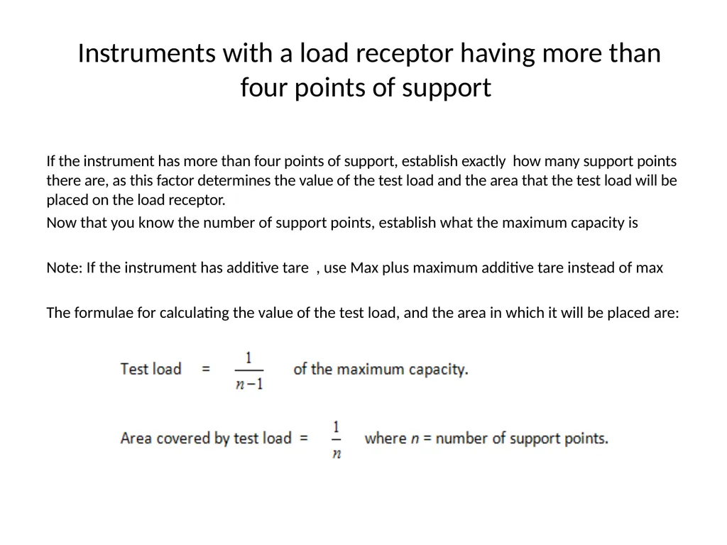
slide5. Instruments with a load receptor having more than four points of support If the instrument has more than four points of support, establish exactly how many support points there are, as this factor determines the value of the test load and the area that the test load will be placed on the load receptor.
Now that you know the number of support points, establish what the maximum capacity is
Note: If the instrument has additive tare , use Max plus maximum additive tare instead of max
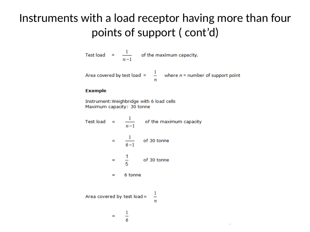
The formulae for calculating the value of the test load, and the area in which it will be placed are:<br>
slide6. Instruments with a load receptor having more than four points of support ( cont’d)<br>
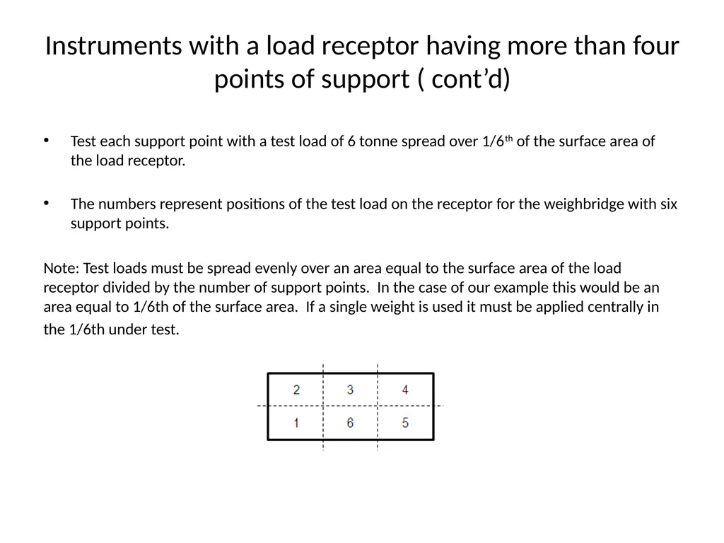
slide7. Instruments with a load receptor having more than four points of support ( cont’d) Test each support point with a test load of 6 tonne spread over 1/6th of the surface area of the load receptor.
The numbers represent positions of the test load on the receptor for the weighbridge with six support points.
Note: Test loads must be spread evenly over an area equal to the surface area of the load receptor divided by the number of support points. In the case of our example this would be an area equal to 1/6th of the surface area. If a single weight is used it must be applied centrally in
the 1/6th under test.<br>
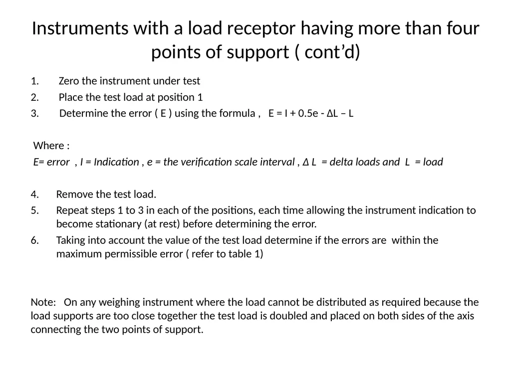
slide9. Instruments with a load receptor having more than four points of support ( cont’d) Zero the instrument under test
Place the test load at position 1
Determine the error ( E ) using the formula , E = I + 0.5e - ∆L – L
Where :
E= error , I = Indication , e = the verification scale interval , ∆ L = delta loads and L = load
Remove the test load.
Repeat steps 1 to 3 in each of the positions, each time allowing the instrument indication to become stationary (at rest) before determining the error.
Taking into account the value of the test load determine if the errors are within the maximum permissible error ( refer to table 1)
Note: On any weighing instrument where the load cannot be distributed as required because the load supports are too close together the test load is doubled and placed on both sides of the axis connecting the two points of support.<br>
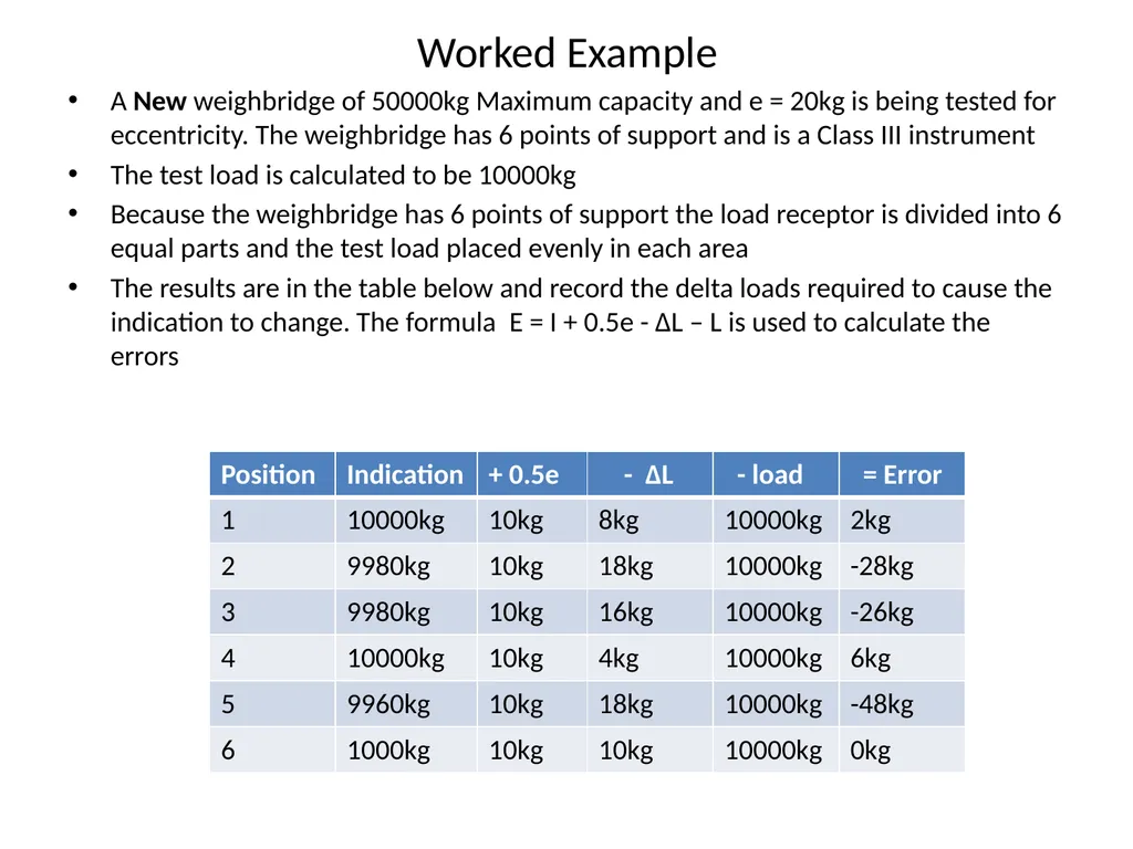
slide10. Worked Example A New weighbridge of 50000kg Maximum capacity and e = 20kg is being tested for eccentricity. The weighbridge has 6 points of support and is a Class III instrument
The test load is calculated to be 10000kg
Because the weighbridge has 6 points of support the load receptor is divided into 6 equal parts and the test load placed evenly in each area
The results are in the table below and record the delta loads required to cause the indication to change. The formula E = I + 0.5e - ∆L – L is used to calculate the errors<br>
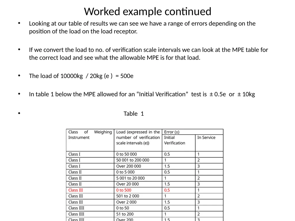
slide11. Worked example continued Looking at our table of results we can see we have a range of errors depending on the position of the load on the load receptor.
If we convert the load to no. of verification scale intervals we can look at the MPE table for the correct load and see what the allowable MPE is for that load.
The load of 10000kg / 20kg (e ) = 500e
In table 1 below the MPE allowed for an “Initial Verification” test is ± 0.5e or ± 10kg
Table 1<br>
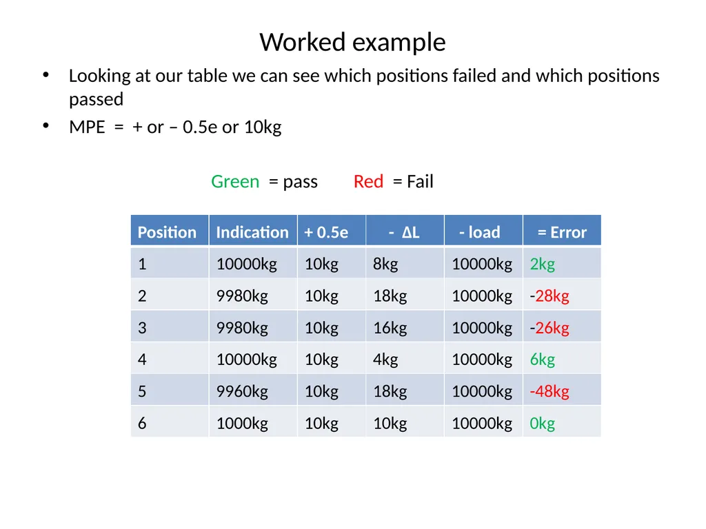
slide12. Worked example Looking at our table we can see which positions failed and which positions passed
MPE = + or – 0.5e or 10kg
Green = pass Red = Fail<br>
slide13. Worked example In the worked example there are 3 positions that exceeded the MPE therefore the instrument fails the eccentricity test for Initial verification
Would the instrument pass if it was an In Service test ?<br>
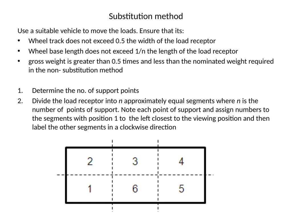
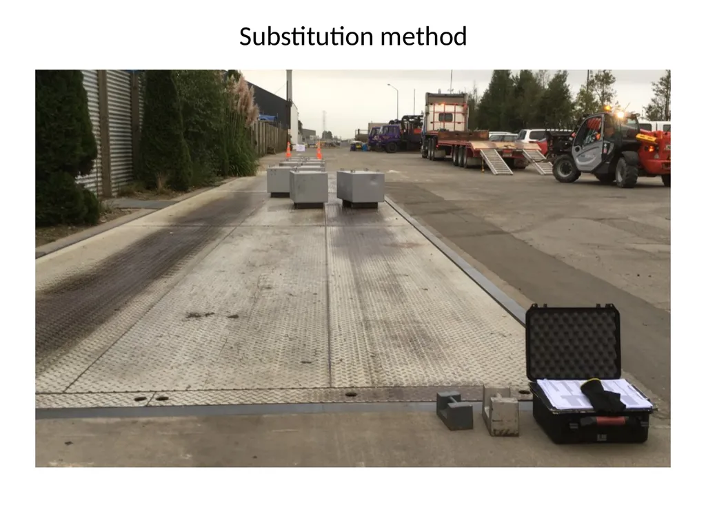
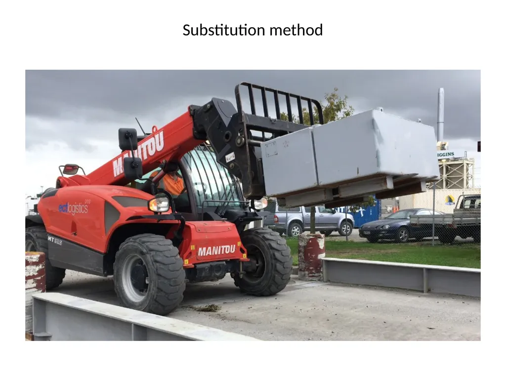
slide14. Substitution method Use a suitable vehicle to move the loads. Ensure that its:
Wheel track does not exceed 0.5 the width of the load receptor
Wheel base length does not exceed 1/n the length of the load receptor
gross weight is greater than 0.5 times and less than the nominated weight required in the non- substitution method
Determine the no. of support points
Divide the load receptor into n approximately equal segments where n is the number of points of support. Note each point of support and assign numbers to the segments with position 1 to the left closest to the viewing position and then label the other segments in a clockwise direction<br>
slide15. Substitution method Note: For rail weighbridges . If two support points are too close together for the load to be distributed as indicated , double the load and distribute over twice the area on both sides of the axis connecting the two points of support.
Determine 1/(n-1) of the Max
Note: if the instrument has additive tare , use max plus maximum additive tare , instead of max.
If this value is :
greater than 5 t go to step 4
Less than or equal to 5 t use the non-substitution method
Determine the weight required for testing. The substitution shall be:
At least 0.5 of the weight determined in step 3: and
No more than the weight determined in step 3.
Zero the instrument
Place standard weights onto the load receptor in the required position , equal to or greater than the weight of the vehicle , provided it is within 0.3 t of the vehicle weight. Record this load (L)
Note: ensure that the placement of the weights does not exceed the wheel track or base dimensions of the vehicle<br>
slide16. Substitution method<br>
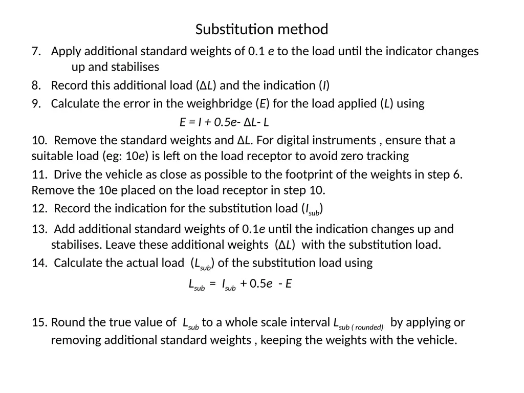
slide17. Substitution method Apply additional standard weights of 0.1 e to the load until the indicator changes up and stabilises
Record this additional load (∆L) and the indication (I)
Calculate the error in the weighbridge (E) for the load applied (L) using
E = I + 0.5e- ∆L- L
10. Remove the standard weights and ∆L. For digital instruments , ensure that a suitable load (eg: 10e) is left on the load receptor to avoid zero tracking
11. Drive the vehicle as close as possible to the footprint of the weights in step 6. Remove the 10e placed on the load receptor in step 10.
Record the indication for the substitution load (Isub)
Add additional standard weights of 0.1e until the indication changes up and stabilises. Leave these additional weights (∆L) with the substitution load.
Calculate the actual load (Lsub) of the substitution load using
Lsub = Isub + 0.5e - E
Round the true value of Lsub to a whole scale interval Lsub ( rounded) by applying or removing additional standard weights , keeping the weights with the vehicle.<br>
slide18. Substitution method<br>
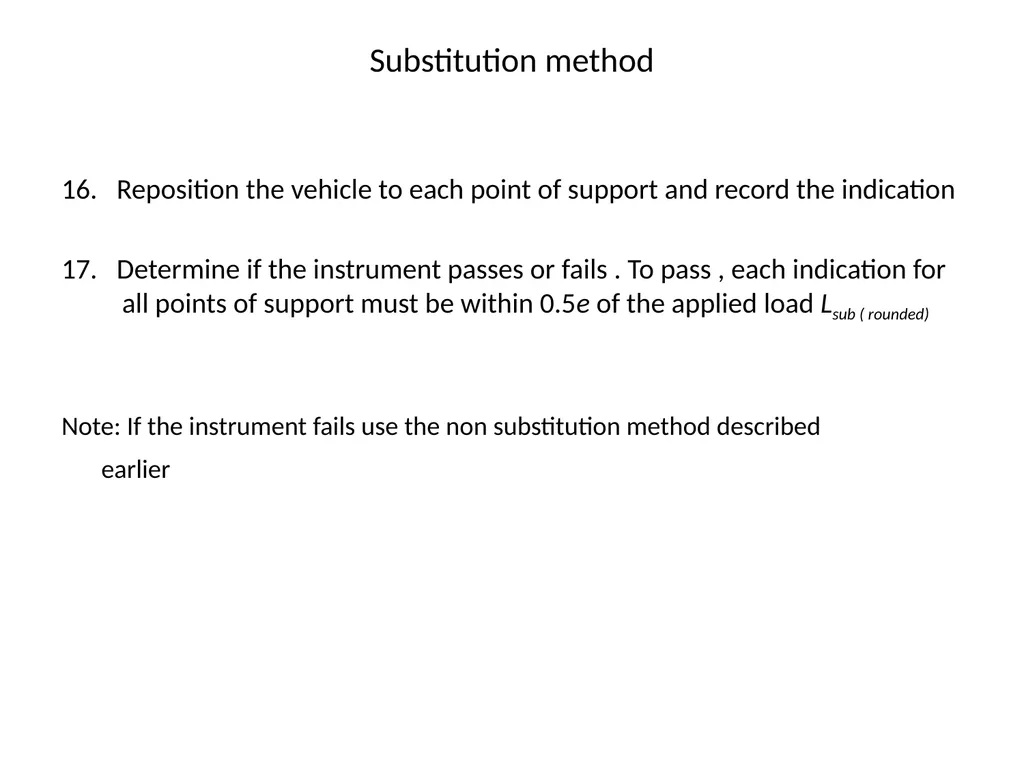
slide19. Substitution method 16. Reposition the vehicle to each point of support and record the indication
17. Determine if the instrument passes or fails . To pass , each indication for all points of support must be within 0.5e of the applied load Lsub ( rounded)
Note: If the instrument fails use the non substitution method described earlier<br>
slide20. Rolling load test Weighbridges used for weighing rolling loads , e.g. vehicles, are tested by using a rolling load
The rolling load is applied at different positions on the load receptor. These positions will be at the beginning, the middle and at the end of the load receptor in the normal direction of travel. The test is then repeated in the reverse direction. There is no requirement restricting the area of the load receptor to be tested.
The test load selected should be of the heaviest and most concentrated load that is normally weighed on the instrument under test and should be between ≥ 20% and ≤ 80% of the maximum capacity.
The actual value of the rolling load must be determined by using the procedure detailed in Eccentricity Substitution method<br>
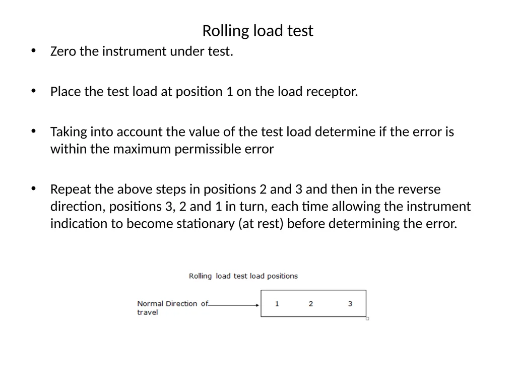
slide21. Rolling load test Zero the instrument under test.
Place the test load at position 1 on the load receptor.
Taking into account the value of the test load determine if the error is within the maximum permissible error
Repeat the above steps in positions 2 and 3 and then in the reverse direction, positions 3, 2 and 1 in turn, each time allowing the instrument indication to become stationary (at rest) before determining the error.<br>
slide22. Group Exercise Work out the loads to apply for the following Instruments;
30000kg , 4 points of support
50000kg , 8 points of support
60000kg , 8 points of support
100000kg , 12 points of support<br>
slide23. Acknowledgement
To the National Measurement Institute of Australia for the section on Substitution testing Eccentricity Test<br>
slide2. Eccentricity - Determining the load to apply Non- Substitution method
Instruments with a load receptor with four points of support or less
Establish if the instrument has four or less support points. If the instrument complies with this condition then the test load is equal to one third of the maximum capacity, plus the corresponding maximum value of any additive tare .
This load must be distributed in an area approximately equal to one-quarter of the surface area of the load receptor.<br>
slide3. Instruments with ≤ 4 points of support (cont’d) Large weights should be used in preference to several small weights. Smaller weights shall be placed on top of larger weights, but unnecessary stacking should be avoided within the segment to be tested.
The diagram below represents the load receptor.
Test loads must be spread evenly over an area corresponding to ¼ of the area of the load receptor in each position. If a single weight is used it must be applied centrally in the ¼ under test.<br>
slide4. Instruments with ≤ 4 points of support (cont’d) Zero the instrument under test.
Place a test load equal to one third of the maximum at position 1
Note: If the instrument has additive tare , use Max plus maximum additive tare instead of max
3. Determine the error ( E ) using the formula , E = I + 0.5e - ∆L – L
Where : E= error , I = Indication , e = the verification scale interval , ∆ L = delta loads and L = load
Taking into account the value of the test load determine if the error is within the maximum permissible error
5. Remove the test load
Repeat steps 1 to 3 in each of the four positions, each time allowing the instrument indication to become stationary (at rest) before determining the error<br>
slide5. Instruments with a load receptor having more than four points of support If the instrument has more than four points of support, establish exactly how many support points there are, as this factor determines the value of the test load and the area that the test load will be placed on the load receptor.
Now that you know the number of support points, establish what the maximum capacity is
Note: If the instrument has additive tare , use Max plus maximum additive tare instead of max
The formulae for calculating the value of the test load, and the area in which it will be placed are:<br>
slide6. Instruments with a load receptor having more than four points of support ( cont’d)<br>
slide7. Instruments with a load receptor having more than four points of support ( cont’d) Test each support point with a test load of 6 tonne spread over 1/6th of the surface area of the load receptor.
The numbers represent positions of the test load on the receptor for the weighbridge with six support points.
Note: Test loads must be spread evenly over an area equal to the surface area of the load receptor divided by the number of support points. In the case of our example this would be an area equal to 1/6th of the surface area. If a single weight is used it must be applied centrally in
the 1/6th under test.<br>
slide9. Instruments with a load receptor having more than four points of support ( cont’d) Zero the instrument under test
Place the test load at position 1
Determine the error ( E ) using the formula , E = I + 0.5e - ∆L – L
Where :
E= error , I = Indication , e = the verification scale interval , ∆ L = delta loads and L = load
Remove the test load.
Repeat steps 1 to 3 in each of the positions, each time allowing the instrument indication to become stationary (at rest) before determining the error.
Taking into account the value of the test load determine if the errors are within the maximum permissible error ( refer to table 1)
Note: On any weighing instrument where the load cannot be distributed as required because the load supports are too close together the test load is doubled and placed on both sides of the axis connecting the two points of support.<br>
slide10. Worked Example A New weighbridge of 50000kg Maximum capacity and e = 20kg is being tested for eccentricity. The weighbridge has 6 points of support and is a Class III instrument
The test load is calculated to be 10000kg
Because the weighbridge has 6 points of support the load receptor is divided into 6 equal parts and the test load placed evenly in each area
The results are in the table below and record the delta loads required to cause the indication to change. The formula E = I + 0.5e - ∆L – L is used to calculate the errors<br>
slide11. Worked example continued Looking at our table of results we can see we have a range of errors depending on the position of the load on the load receptor.
If we convert the load to no. of verification scale intervals we can look at the MPE table for the correct load and see what the allowable MPE is for that load.
The load of 10000kg / 20kg (e ) = 500e
In table 1 below the MPE allowed for an “Initial Verification” test is ± 0.5e or ± 10kg
Table 1<br>
slide12. Worked example Looking at our table we can see which positions failed and which positions passed
MPE = + or – 0.5e or 10kg
Green = pass Red = Fail<br>
slide13. Worked example In the worked example there are 3 positions that exceeded the MPE therefore the instrument fails the eccentricity test for Initial verification
Would the instrument pass if it was an In Service test ?<br>
slide14. Substitution method Use a suitable vehicle to move the loads. Ensure that its:
Wheel track does not exceed 0.5 the width of the load receptor
Wheel base length does not exceed 1/n the length of the load receptor
gross weight is greater than 0.5 times and less than the nominated weight required in the non- substitution method
Determine the no. of support points
Divide the load receptor into n approximately equal segments where n is the number of points of support. Note each point of support and assign numbers to the segments with position 1 to the left closest to the viewing position and then label the other segments in a clockwise direction<br>
slide15. Substitution method Note: For rail weighbridges . If two support points are too close together for the load to be distributed as indicated , double the load and distribute over twice the area on both sides of the axis connecting the two points of support.
Determine 1/(n-1) of the Max
Note: if the instrument has additive tare , use max plus maximum additive tare , instead of max.
If this value is :
greater than 5 t go to step 4
Less than or equal to 5 t use the non-substitution method
Determine the weight required for testing. The substitution shall be:
At least 0.5 of the weight determined in step 3: and
No more than the weight determined in step 3.
Zero the instrument
Place standard weights onto the load receptor in the required position , equal to or greater than the weight of the vehicle , provided it is within 0.3 t of the vehicle weight. Record this load (L)
Note: ensure that the placement of the weights does not exceed the wheel track or base dimensions of the vehicle<br>
slide16. Substitution method<br>
slide17. Substitution method Apply additional standard weights of 0.1 e to the load until the indicator changes up and stabilises
Record this additional load (∆L) and the indication (I)
Calculate the error in the weighbridge (E) for the load applied (L) using
E = I + 0.5e- ∆L- L
10. Remove the standard weights and ∆L. For digital instruments , ensure that a suitable load (eg: 10e) is left on the load receptor to avoid zero tracking
11. Drive the vehicle as close as possible to the footprint of the weights in step 6. Remove the 10e placed on the load receptor in step 10.
Record the indication for the substitution load (Isub)
Add additional standard weights of 0.1e until the indication changes up and stabilises. Leave these additional weights (∆L) with the substitution load.
Calculate the actual load (Lsub) of the substitution load using
Lsub = Isub + 0.5e - E
Round the true value of Lsub to a whole scale interval Lsub ( rounded) by applying or removing additional standard weights , keeping the weights with the vehicle.<br>
slide18. Substitution method<br>
slide19. Substitution method 16. Reposition the vehicle to each point of support and record the indication
17. Determine if the instrument passes or fails . To pass , each indication for all points of support must be within 0.5e of the applied load Lsub ( rounded)
Note: If the instrument fails use the non substitution method described earlier<br>
slide20. Rolling load test Weighbridges used for weighing rolling loads , e.g. vehicles, are tested by using a rolling load
The rolling load is applied at different positions on the load receptor. These positions will be at the beginning, the middle and at the end of the load receptor in the normal direction of travel. The test is then repeated in the reverse direction. There is no requirement restricting the area of the load receptor to be tested.
The test load selected should be of the heaviest and most concentrated load that is normally weighed on the instrument under test and should be between ≥ 20% and ≤ 80% of the maximum capacity.
The actual value of the rolling load must be determined by using the procedure detailed in Eccentricity Substitution method<br>
slide21. Rolling load test Zero the instrument under test.
Place the test load at position 1 on the load receptor.
Taking into account the value of the test load determine if the error is within the maximum permissible error
Repeat the above steps in positions 2 and 3 and then in the reverse direction, positions 3, 2 and 1 in turn, each time allowing the instrument indication to become stationary (at rest) before determining the error.<br>
slide22. Group Exercise Work out the loads to apply for the following Instruments;
30000kg , 4 points of support
50000kg , 8 points of support
60000kg , 8 points of support
100000kg , 12 points of support<br>
slide23. Acknowledgement
To the National Measurement Institute of Australia for the section on Substitution testing Eccentricity Test<br>