Wireless Power How it works Disclaimer: The purpose of this information is to explain the wireless power technology It can differ in some aspects from the specification. Target Main application Battery charging, or other suitable loads
"Wireless Power How it works Disclaimer: The" is the property of its rightful owner. Permission is granted to
download and print the materials on this website for personal, non-commercial use only, and to display it
on your personal computer provided you do not modify the materials and that you retain all copyright
notices contained in the materials. By downloading content from our website, you accept the terms of this
agreement.
Presentation Transcript
01
Wireless Power How it works Disclaimer: The purpose of this information is to explain the wireless power technology – It can differ in some aspects from the specification.<br>
02
Target Main application
Battery charging, or other suitable loads
For wide range of mobile devices
Mobile phone, camera, mp3 player, headset, …
Up to 5W of power delivery
More power at later versions
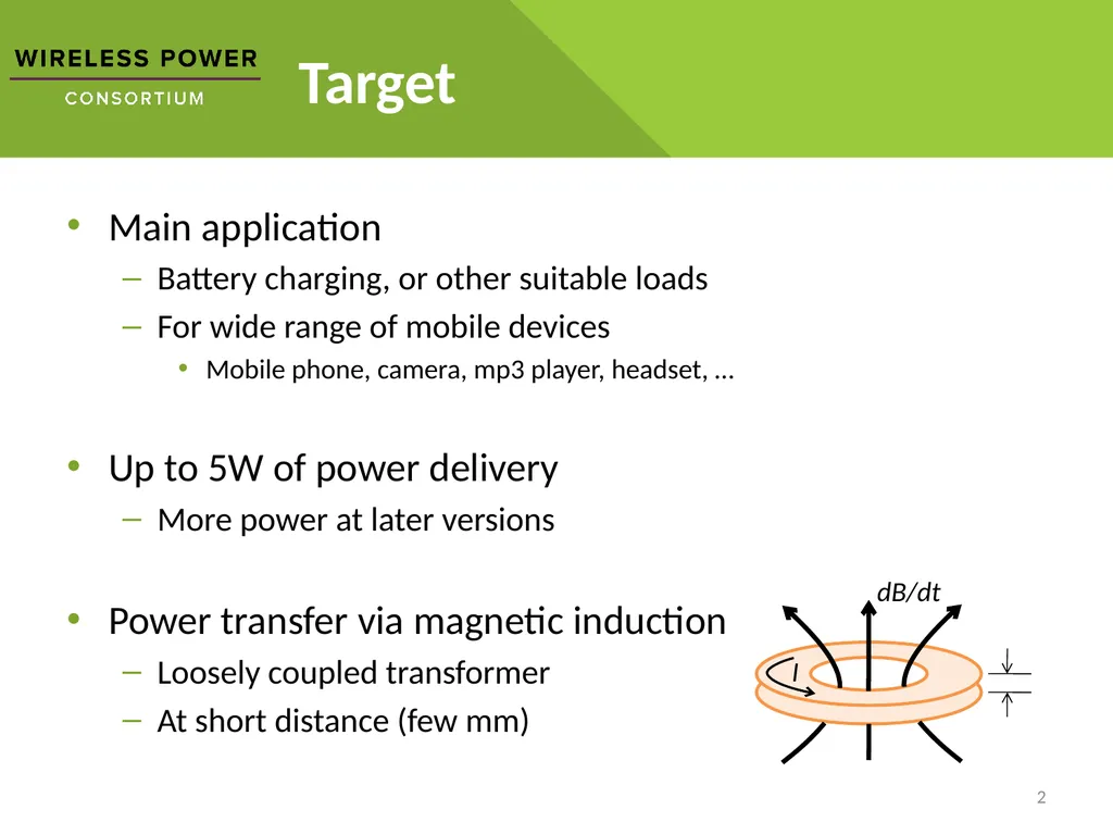
Power transfer via magnetic induction
Loosely coupled transformer
At short distance (few mm) 2<br>
03
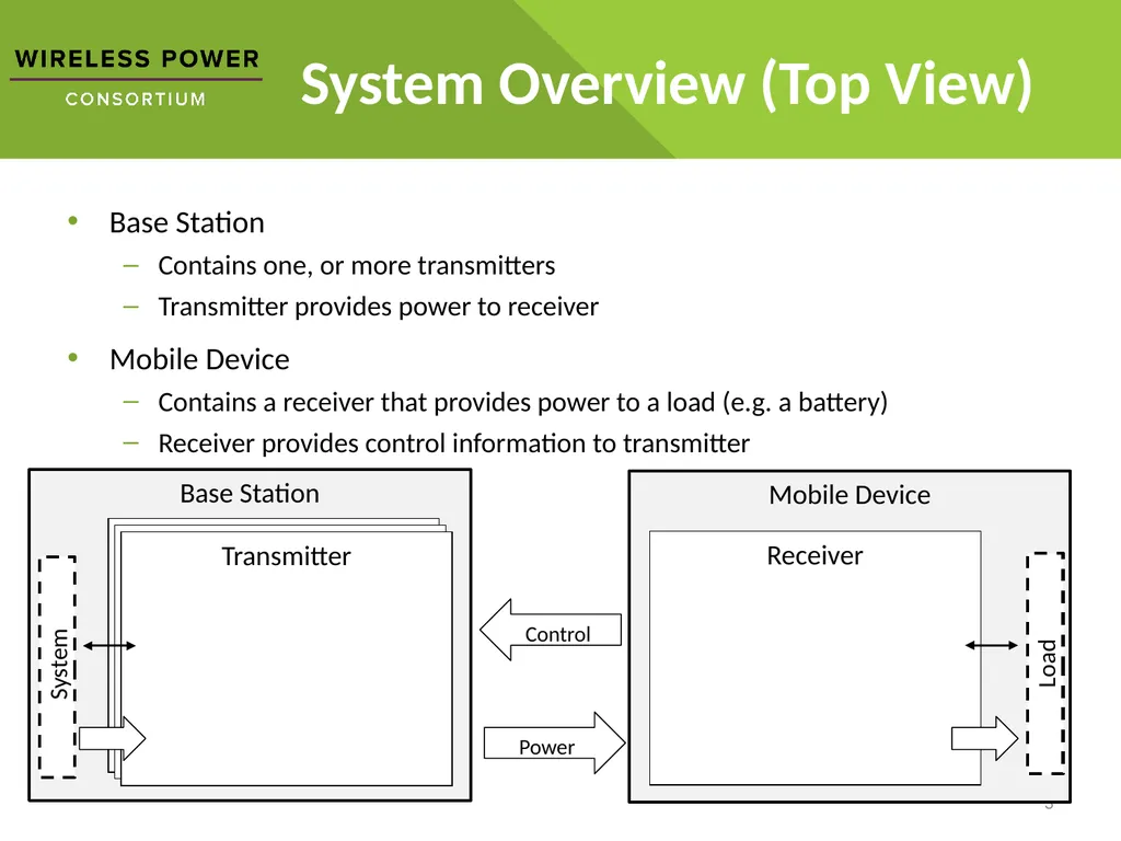
Base Station Transmitter Transmitter System Overview (Top View) Base Station
Contains one, or more transmitters
Transmitter provides power to receiver
Mobile Device
Contains a receiver that provides power to a load (e.g. a battery)
Receiver provides control information to transmitter 3 Mobile Device Receiver Transmitter Load System Power Control<br>
04
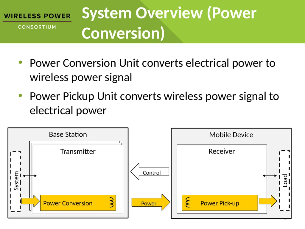
Base Station Transmitter Transmitter System Overview (Power Conversion) Power Conversion Unit converts electrical power to wireless power signal
Power Pickup Unit converts wireless power signal to electrical power 4 Mobile Device Receiver Transmitter Load System Power Control<br>
05
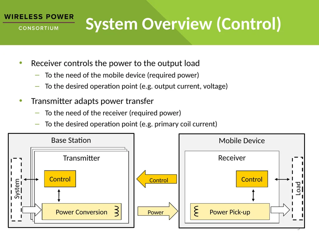
Base Station Transmitter Transmitter System Overview (Control) Receiver controls the power to the output load
To the need of the mobile device (required power)
To the desired operation point (e.g. output current, voltage)
Transmitter adapts power transfer
To the need of the receiver (required power)
To the desired operation point (e.g. primary coil current) 5 Mobile Device Receiver Transmitter Load System Power Control Control Control<br>
06
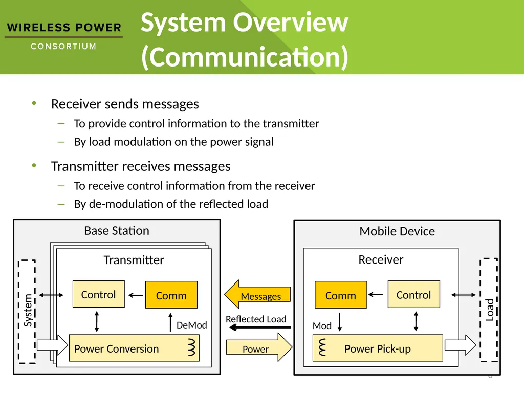
Base Station Transmitter Transmitter System Overview (Communication) Receiver sends messages
To provide control information to the transmitter
By load modulation on the power signal
Transmitter receives messages
To receive control information from the receiver
By de-modulation of the reflected load 6 Mobile Device Receiver Transmitter Load System Power Control Control Messages Comm Comm Reflected Load Mod DeMod<br>
07
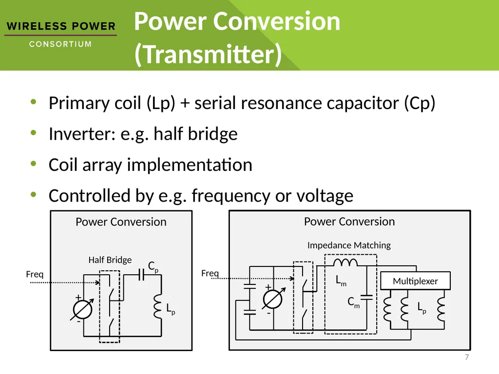
Power Conversion Power Conversion (Transmitter) Primary coil (Lp) + serial resonance capacitor (Cp)
Inverter: e.g. half bridge
Coil array implementation
Controlled by e.g. frequency or voltage 7 Power Conversion<br>
08
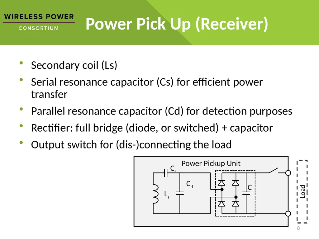
Power Pickup Unit Power Pick Up (Receiver) Secondary coil (Ls)
Serial resonance capacitor (Cs) for efficient power transfer
Parallel resonance capacitor (Cd) for detection purposes
Rectifier: full bridge (diode, or switched) + capacitor
Output switch for (dis-)connecting the load 8<br>
09
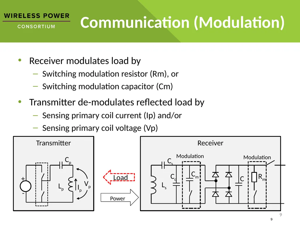
Transmitter Receiver Communication (Modulation) Receiver modulates load by
Switching modulation resistor (Rm), or
Switching modulation capacitor (Cm)
Transmitter de-modulates reflected load by
Sensing primary coil current (Ip) and/or
Sensing primary coil voltage (Vp) 9 Cd Ls Cs C 9 Load Power<br>
10
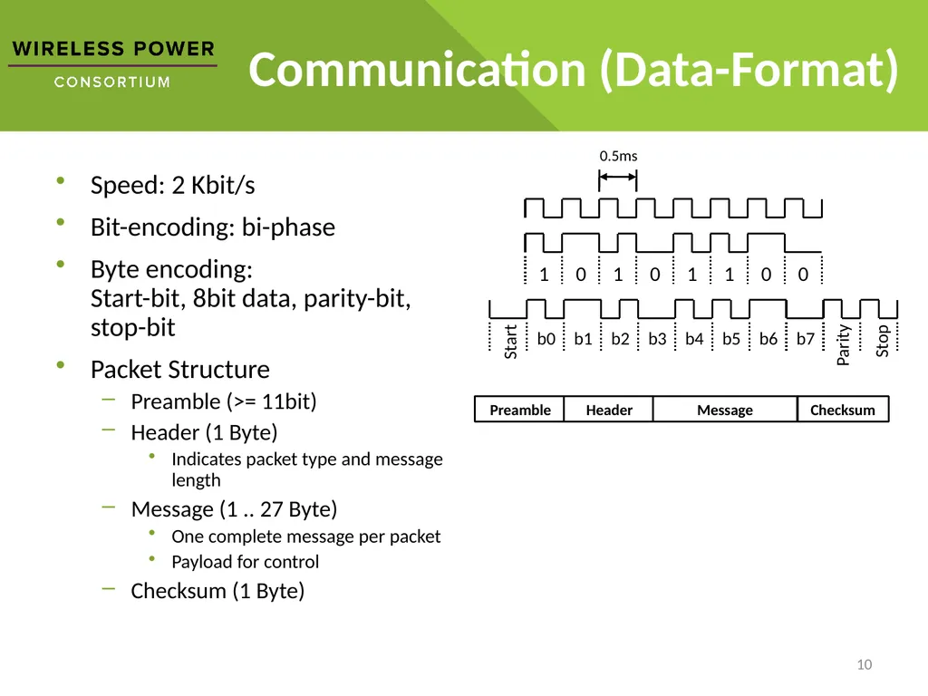
Communication (Data-Format) Speed: 2 Kbit/s
Bit-encoding: bi-phase
Byte encoding: Start-bit, 8bit data, parity-bit, stop-bit
Packet Structure
Preamble (>= 11bit)
Header (1 Byte)
Indicates packet type and message length
Message (1 .. 27 Byte)
One complete message per packet
Payload for control
Checksum (1 Byte) 10<br>
11
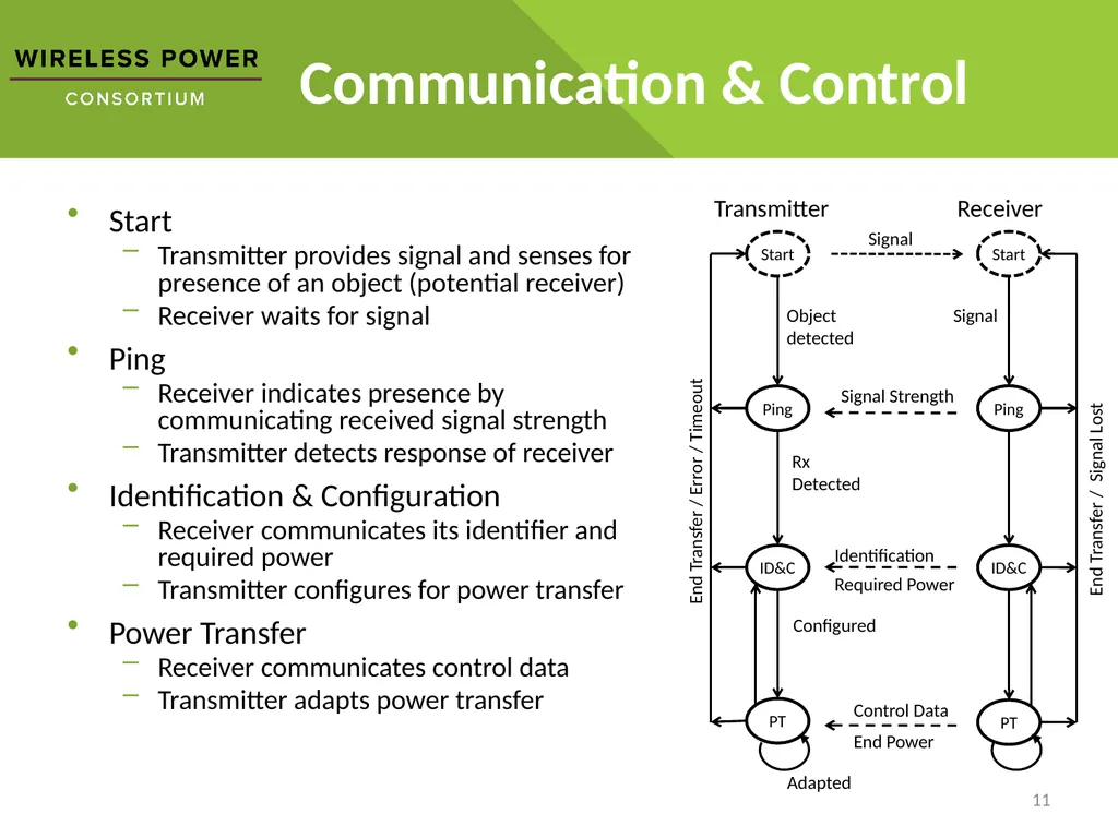
Communication & Control Start
Transmitter provides signal and senses for presence of an object (potential receiver)
Receiver waits for signal
Ping
Receiver indicates presence by communicating received signal strength
Transmitter detects response of receiver
Identification & Configuration
Receiver communicates its identifier and required power
Transmitter configures for power transfer
Power Transfer
Receiver communicates control data
Transmitter adapts power transfer 11<br>
12
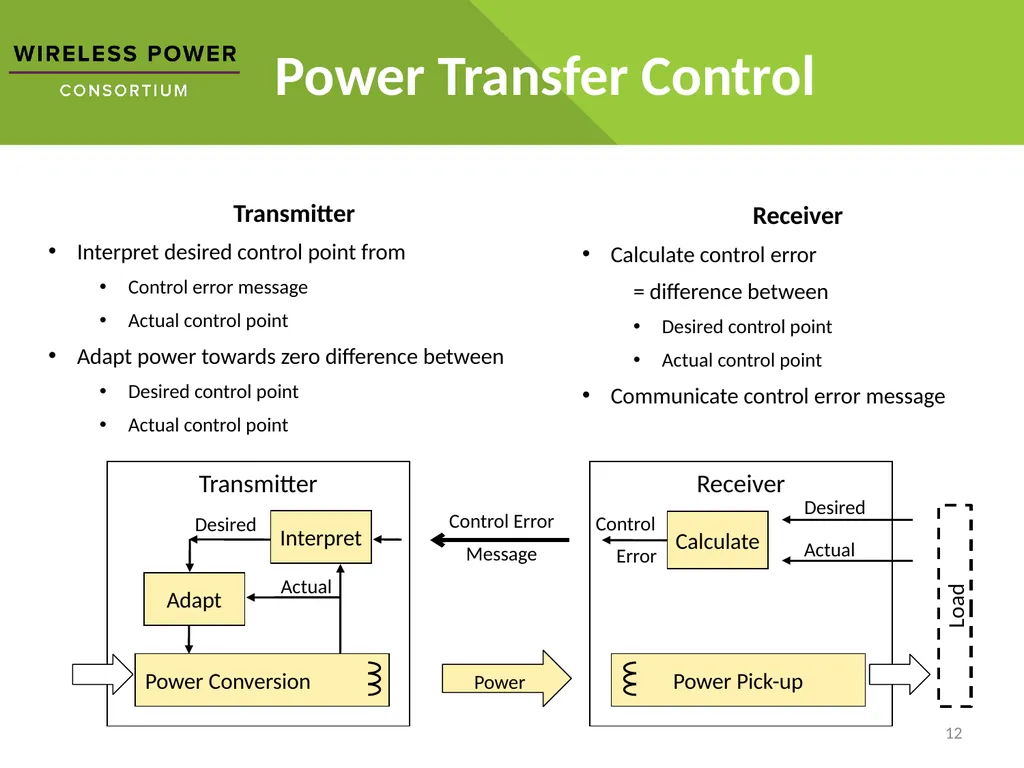
Power Transfer Control 12 Transmitter
Interpret desired control point from
Control error message
Actual control point
Adapt power towards zero difference between
Desired control point
Actual control point Receiver
Calculate control error
= difference between
Desired control point
Actual control point
Communicate control error message Receiver Transmitter Load Power<br>
13
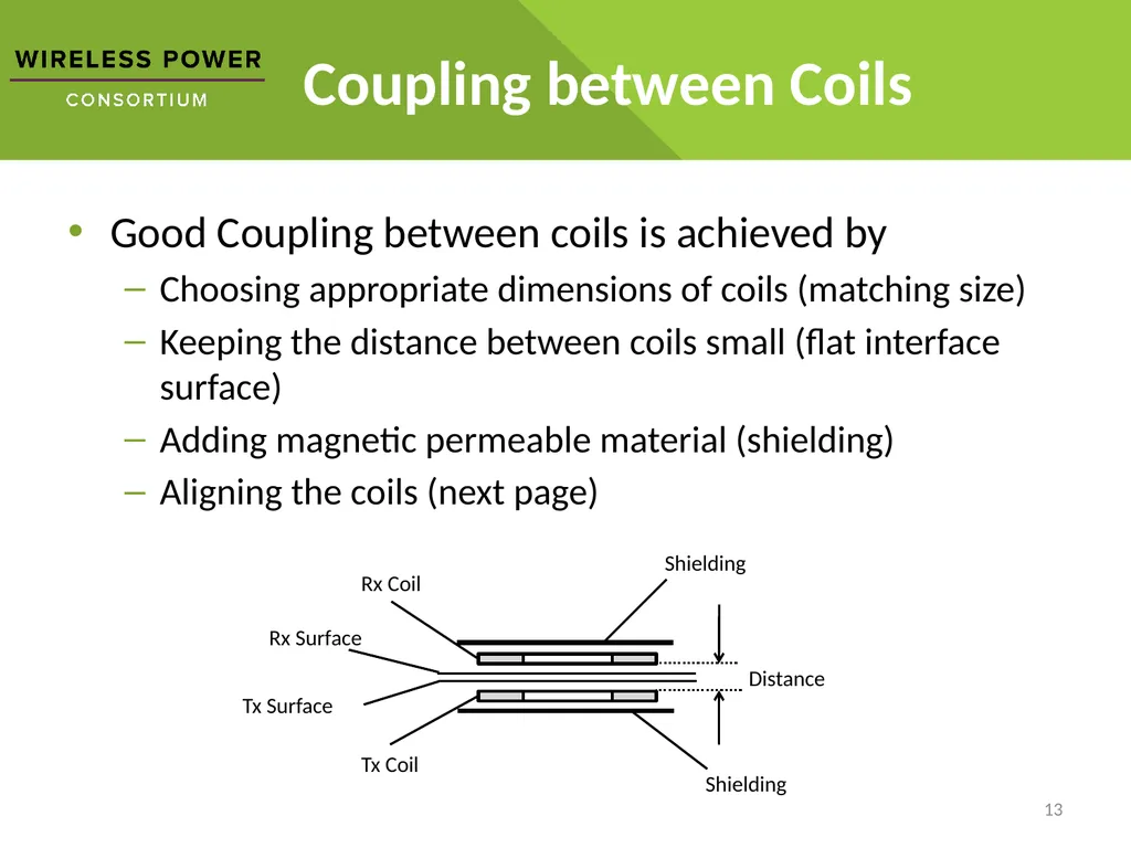
Coupling between Coils Good Coupling between coils is achieved by
Choosing appropriate dimensions of coils (matching size)
Keeping the distance between coils small (flat interface surface)
Adding magnetic permeable material (shielding)
Aligning the coils (next page) 13<br>
14
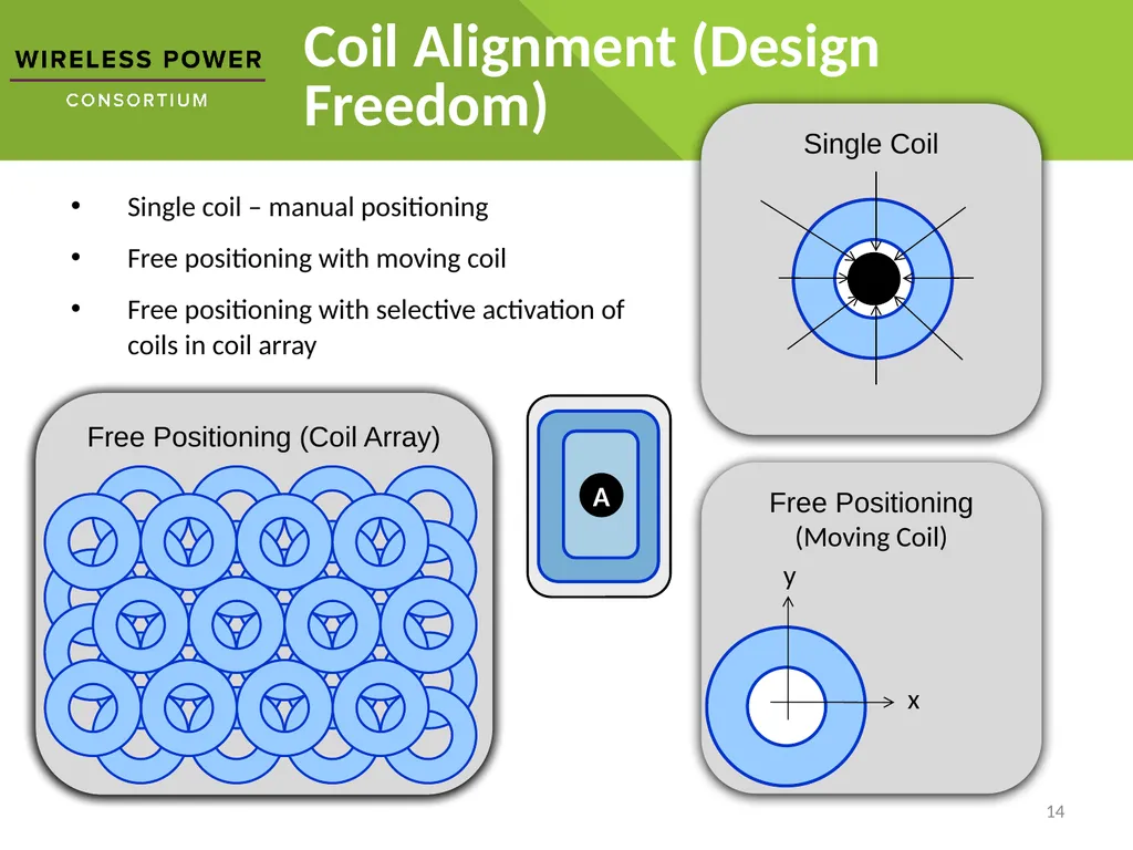
Free Positioning
(Moving Coil) Coil Alignment (Design Freedom) 14 Free Positioning (Coil Array) Single Coil x y Single coil – manual positioning
Free positioning with moving coil
Free positioning with selective activation of coils in coil array<br>
15
Standby Power Transmitter can enter standby power mode when
No device is present, or
present devices need no power (battery charged)
Transmitter can apply various methods to react on a receiver
Capacitance change
To detect the placement of a potential receiver
E.g. 0.1 mW
Resonance detection , or
Resonance change
To detect the presence and location of a potential receiver
E.g. 5 mW per primary coil when applied every 0.5s
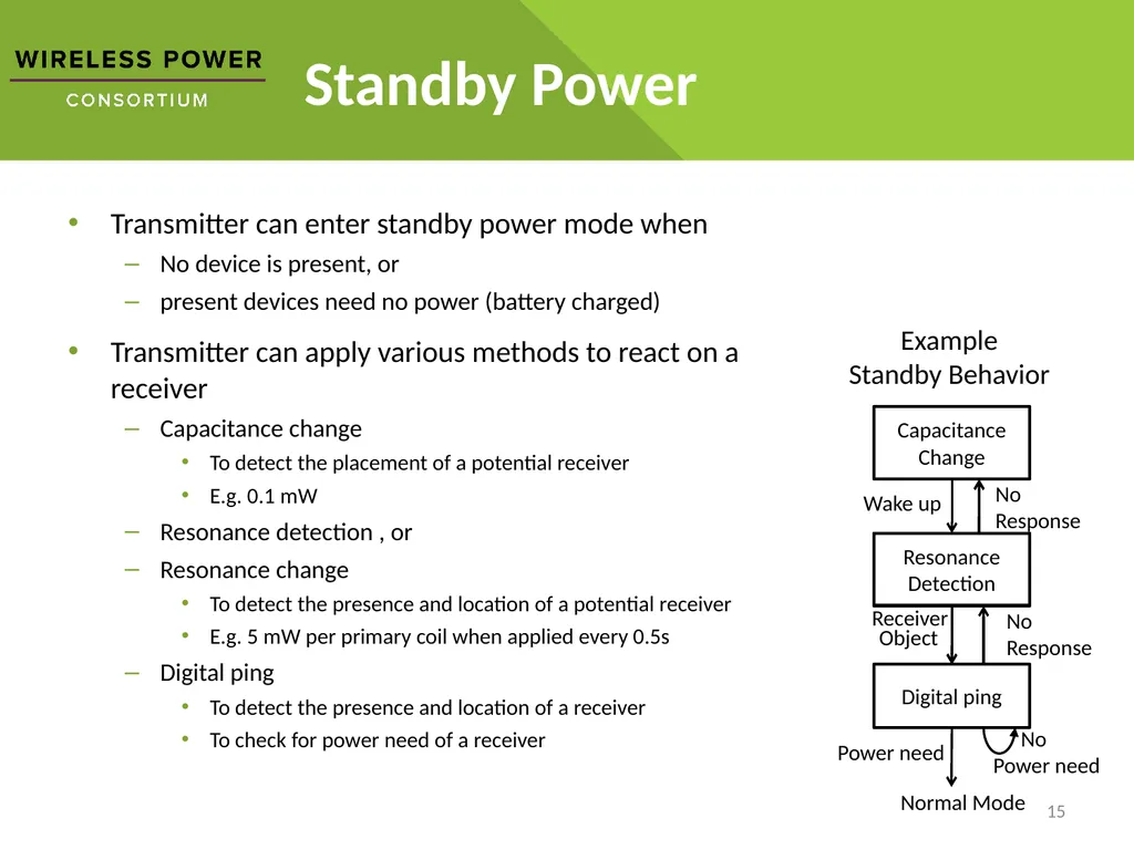
Digital ping
To detect the presence and location of a receiver
To check for power need of a receiver 15 Example
Standby Behavior Normal Mode<br>