/
Analysis of Statically Indeterminate Structures by the Direct Stiffnes Analysis of Statically Indeterminate Structures by the Direct Stiffnes

Analysis of Statically Indeterminate Structures by the Direct Stiffnes - PDF document

yoshiko-marsland
yoshiko-marsland . @yoshiko-marsland
Follow
393 views
Uploaded On 2015-11-02

Analysis of Statically Indeterminate Structures by the Direct Stiffnes - PPT Presentation

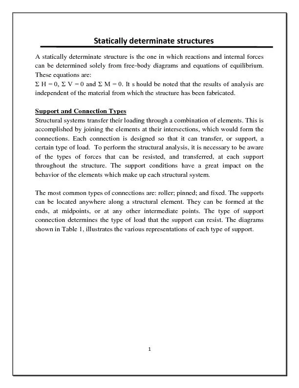
Module 4 Version 2 CE IIT Kharagpur In the above figures single he 272 Beam Stiffness Matrix Fig 272 shows a prismatic beam of a cons ID: 180378

Module Version

Share:

Link:

Embed:

Download Presentation from below link

Download Pdf The PPT/PDF document "Analysis of Statically Indeterminate Str..." is the property of its rightful owner. Permission is granted to download and print the materials on this web site for personal, non-commercial use only, and to display it on your personal computer provided you do not modify the materials and that you retain all copyright notices contained in the materials. By downloading content from our website, you accept the terms of this agreement.


Presentation Transcript

Module 4 Analysis of Statically Indeterminate Structures by the Direct Stiffness Method Version 2 CE IIT, Kharagpur In the above figures, single he 27.2 Beam Stiffness Matrix. Fig. 27.2 shows a prismatic beam of a constant cross section that is fully are denoted by nodes '''zyx j axis coincides with the centroidal axis of k 'x j to. Let k L be the length of the member, A axis. zzI z ees of freedom for erclockwise rotations are taken as positive. The positive sense of the translafigure. Displacements are css matrix indicate t 44 Version 2 CE IIT, Kharagpur the member by the restraints at the ends of the member when imposed along each degree zero. Now impose a unit axis at 'y j 27.3a. This displacement causes both figure. By definition they are elements particular they form the first column In Fig. 27.3b, the unit rotation in the positive sense is imposed at j displacements to zero. The restraint actions are at ends are calculated referring to Version 2 CE IIT, Kharagpur shown in Fig. 27.4 is possible. In such a case the first and the third rows and 4224 (27.2) displacement along 'y j 27.3a, apply a displacement 1'u 'y j s to zero. Let the restraining forces 312111,,qqq 41q Version 2 CE IIT, Kharagpur The forces are equal to, 14141131311212111111;';';'ukqukqukqukq (27.3) simultaneously along displacement respective degrees of freedom. Then by the principle of superposition, the force 321',','uuu 4'u 3,2,1 4 321,,qqq 4q 4626126122646612612 (27.4) This may also be written in compact form as, ukq (27.5) Version 2 CE IIT, Kharagpur .8(a), is equal to the sum of Fig. 27.8(b) and Fig. 27.8(c). In Fig. 27.8(displacements and fixed end forces are calculated. In Fig. 27.on on the actual beam without any load. Since the beam in Fig. 27.8(b) is restrained (fixed) against any displacement, the Version 2 CE IIT, Kharagpur KKKKKK (27.14a) Equation (27.14a) may be written as,  KKKKKKLPaLPb (27.14b) Member end actions are calculated as follows. For example consider the first element 1. 4321,,,qqqq bPa (27.16) lved to illustrate the method so far discussed. Summary The global load vector is defined. The global load-displacemet relation is written procedure to impose boundary conditions on the load-displacement relation is discussed. With this background, one could Version 2 CE IIT, Kharagpur