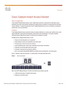
All rights reserved This document is Cisco Public Information Page of 18 White Paper Cisco Catalyst Instant Access Solution What You Will Learn Cisco Catalyst Instant Access creates a single network touch point and a single point ID: 7096
Download Pdf The PPT/PDF document " Cisco andor its affiliate " is the property of its rightful owner. Permission is granted to download and print the materials on this web site for personal, non-commercial use only, and to display it on your personal computer provided you do not modify the materials and that you retain all copyright notices contained in the materials. By downloading content from our website, you accept the terms of this agreement.
© 2016 Cisco and/or its affiliates . All rights reserved. This document is Cisco Public Information. Page 1 of 30 White Paper Cisco Catalyst Instant Access Solution What You Will Learn Cisco Catalyst ® Instant Access creates a single network touch point and a single point of configuration across distribution and access layer switches, dramatically simplifying design, deployment, a nd operations for enterprise campus networks. This paper discusses the Cisco ® Catalyst Instant Access Solutionâs architecture, components, packet walks, and value proposition. Overview Cisco Catalyst Instant Access enables the merging of physical distribut ion and access layer switches into a single logical entity with a single point of configuration, management, and troubleshooting. The solution simplifies enterprise campus networks by bringing in provisioning and operational simplicity. Benefits of Cisco C atalyst Instant Access include: â Single point of configuration and management â Single software image across distribution and access layers â âPlug and playâ provisioning of access switches â Agile infrastructure at the access layer, with feature and hardware con sistency â Automatic uplink configuration at the access layer â Automatic image provisioning of access switches â Rich and consistent Catalyst 6500/6800 Series feature set across distribution and access layers Figure 1 depicts a single touch point for a 21 acces s switch ( 1000 - port) distribution block. Figure 1. Single Logical Switch With Cisco I OS ® Software Release 15.1(2)SY, the Instant Access solution support s : â 1008 host ports across 21 Instant Access clients â S tacking of up to three clients © 2016 Cisco and/or its affi liates . All rights reserved. This document is Cisco Public Information. Page 2 of 30 With Cisco IOS Software Rele ase 15.2(1)SY 1 , the Instant Access solution supports : â 15 36 host ports on Supervisor 2T - based systems on a modula r chassis (1200 ports with release 15.2(1)SY) â U p to 2016 host ports on the Cisco Catalyst 6880 - X Switch â S tacking of up to five clients Consider the topology outlined in Figure 2 . It includes a 4032 - port campus network with four distribution blocks , each consisting of 1008 ports (21 access switches of 48 ports each) with a Cisco Virtual Switching System (VSS) pair at the distribution , and stacking technology at the access layer. This campus requires: â 29 devices for configuration management â 29 devices for image management â 48 trunks and port - channel configurations on access switches â 29 separate configurations, including Simple Network Management Proto col (SNMP) , Network Time Protocol (NTP) , TACACS/RADIUS, VLAN database , management IP, gateway, and host name As shown in Figure 3, with Cisco Catalyst Instant Access, the same 4032 - port campus would require only: â Five total devices to manage â No image manag ement at access switches â No uplink trunk configuration on access switches â Five separate configurations for SNMP, NTP, TACACS, VLAN DB, management IP, and hostname Figure 2. Traditional Deployment Figure 3. Instant Access Deployment System Components The Instant Access sol ution has two components: the Instant Access parent and the Instant Access client (Figure 4). Instant Access parent: The Instant Access parent switch comprises a pair of Cisco Catalyst 6500 - E or 680 7 - XL Series chassi s with Supervisor 2T configured in VSS o r VSS Quad - Sup SSO 1 mode and a WS - 6904 40G/10G line card configured in 10 - G b mode. Details on configuring in VSS and VSS Quad - Sup SSO mode can be found here . Details on 40 - G b line cards operating in 10 - G b mode can be found here . © 2016 Cisco and/or its affi liates . All rights reserved. This document is Cisco Public Information. Page 3 of 30 1 Certain deployments may not have a VSS pair at the distribution lay er. In such cases, a single Cisco Catalyst 6500 or 6800 Series s witch can be used. The switch needs to be configured in VSS mode because the Instant Access solution treats each Instant Access client as a remote line card and uses a VSS infrastructure to en able this remote - line - card - like capability. It is not recommended to deploy Instant Access with a single switch at the distribution layer ; however, if configured, it is recommended to have two supervisors in the chassis in case of failure of one supervisor engine. However , note that since Instant Access requires VSS mode, if a single chassis is used with dual supervisors and the active supervisor goes down, the entire system reloads ( no RPR or SSO is maintained between the supervisors ) . (A single chassis wi th dual supervisors without Instant Access does not require VSS mode , and therefore can maintain Route Processor Redundancy ( RPR ) or stateful switchover ( SSO ) between the supervisors.) . Instant Access parent functionality is also supported on a Cisco Cata lyst 6880 - X or 6880 - X - LE Switch VSS pair. Instant Access is supported on all ports on the baseboard and on the port cards of this chassis . With the Release of 15.2(2)SY, t he newer Cisco Catalyst 6840 - X series s witches also support Instant Access parent functionality on the onboard 10 Gigabit Ethernet ( 10 - G E ) and 1 - G E ports, across all the four models of switches. With Release 15.2 (1)SY, the latest 10 - GE line cards in the modular portfolio include Instant Access parent functionality on Cisco Catalyst 6500 - E Series and 6807 - XL Chassis . A complete list of hardware supporting the Cisco Catalyst Instant Access parent functionality follo ws . â Modular chassis: Cisco Catalyst 6500 - E S eries chassis or 6807 - XL chassis The modular chassis r equires Supervisor Engine 2T ( VS - S2T - 10G or VS - S2T - 10G - XL) along with any of the following line cards : ⦠WS - X6904 - 40G - 2T, WS - X6904 - 40G - 2TXL (Instant Access por ts in 10 - G b mode) ⦠C6800 - 32P10G, C6800 - 32P10G - XL ⦠C6800 - 16P10G, C6800 - 16P10G - XL ⦠C6800 - 8P10G, C6800 - 8P10G - XL â Fixed Chassis: All ports of Catalyst C6880 - X and C6880 - X - LE s witches , and a ll models of the Catalyst 6840 - X Switch Instant Access client : The Instant Access client is a Cisco Catalyst 68 00 ia S eries s witch operating exclusively in client mode with a Cisco Catalyst 6500 - E or 6800 Series switch at the distribution layer. The 6800ia switch is not intended to be used at the aggregation layer, and it is best practice to connect the 6800ia to end hosts or compact switches downstream. The Cisco Catalyst I OS Release 15.2(1)SY adds support for a compact switch in the Catalyst 3560 - CX family as an Instant Access client, which can operate either as a standalone swi tch or as an Instant Access client. 15.2(1)SY1 adds support for a second compact switch as a client , which also belongs to the Catalyst 3560CX family and supports mGig (or Multi rate Gigabit Ethernet ) connectivity . The 6800ia Instant Access client supports 48 10/100/1000 interfaces and two 10 Gbps uplink or fabric interface ports. The high - level features and capabilities of the Instant Access client are: â 48 10/100/1000 BASE - T host ports with Power over Ethernet+ ( PoE+ ) or non - PoE options â Two 10 - Gbps uplink p orts â 740 W atts PoE power : ⦠Full PoE (15 W atts ) across all 48 ports ⦠Full PoE+ (30 W atts ) across any 24 ports â Stackable up to five clients â 80 Gbps of bi directional stack bandwidth © 2016 Cisco and/or its affi liates . All rights reserved. This document is Cisco Public Information. Page 4 of 30 â Operates in Instant Access client mode only with centralized packet switching o n the Instant Access parent â A separate SKU with a redundant power supply is available The Cisco Catalyst 6800ia families of switches have differing power configurations. The first two models, C6800IA - 48TD (data - only) , and C6800IA - 48FPD (PoE/PoE+) , support a single , built - in power supply and fan. The power redundancy for these two models is supported by an external Cisco Redundant Power System ( RPS ) . A third model , C6800IA - 48FPDR (PoE/PoE+) , supports two redundant removable power supplies, and each power sup ply has a power budget of 1025 W atts of total system power. The 1025 - W att power supply has an inline power budget of 740 W atts . More details are available here . Figure 4. Cisco Catalyst Instant Access Components In addition to the parent and client, a fex - fabric link between the Instant Access parent and client supports short - reach, long - reach multimode, long - reach, and extended - reach optics wit h Cisco 10GBase SFP+ across fabric links. For more details, click here . As mentioned above , with Cisco Catalyst I OS Release 15.2(1)SY, a new Instant Access c lient has been added to the portfolio. It is the Cisco Catalyst 3560 - CX Series compact s witch (Figure 5; SKU : WS - C3560CX - 12PD - S ) , which is able to function as an Instant Access client connected to the Catalyst 6500/6800 parent switch. Figure 5. 3560 - CX Series: New I nstant Access Compact C lient © 2016 Cisco and/or its affi liates . All rights reserved. This document is Cisco Public Information. Page 5 of 30 The high - level features and capabilities of this I nstant A ccess client include : â Twelve 10/100/1000 BASE - T host ports with PoE â Two 10 - Gbps SFP+ or 1 - Gbps SFP uplink ports (used for Instant Access) â Two 10/100/1000 BASE - T uplin k p orts ( not used for Instant Access) â 240 W atts of PoE p ower: ⦠Full PoE (15 W atts ) across all 12 ports ⦠Full PoE+ (30 W atts ) across any 8 ports â Does not support stacking â Fanless switch with a single built - in power supply â Operates in both Instant Access mode and standalone mode The 12 - port 3560 - CX switch is available in three SKUs: WS - C 3560CX - 12TC - S , WS - C3560CX - 12P C - S , and WS - C3560CX - 12PD - S . Of these products, only the WS - C3560CX - 12PD - S is supported as an Instant Access client. More details are available here . With a subsequent release, a second compact switch , WS - C3560CX - 8XPD - S , is supported as an Instant Access client. More detail s can be found here . The Instant Access solution supports a mix of both 6800ia and 3560 - CX switches as clients from the same parent switch. Components are shown in Figure 6. Note: 3560 - CX compact switches are not supported in Catalyst 6840 family as Instant Access Client Figure 6. Instant Access Components © 2016 Cisco and/or its affi liates . All rights reserved. This document is Cisco Public Information. Page 6 of 30 Cisco Catalyst Instant Access Architecture Control Plane The control plane implementati on in the Instant Access solution allows for the logical grouping of all access switches into one entity. The control plane has four main components: â Satellite Discovery Protocol (SDP). This link - based protocol runs on every link between the Instant Access parent and clients. It establishes, monitors, and maintains fabric link connectivity and allows for a Multichassis EtherChannel connection across parent and client. SDP configures fabric uplinks at the client with no human intervention, providing zero - tou ch client installation. â Satellite Registration Protocol (SRP). This protocol registers the Instant Access client and performs an image check and automatic upgrade of the client to match the image on the Instant Access parent. This occurs for both new clien ts and new client stack members as they are added to the stack. SRP provides the ability for online insertion and removal (OIR) and auto provisioning of the client. SRP removes the need for image management at the access layer, which provides the added ben efit of Cisco IOS Software feature consistency across the distribution and access layers. â Satellite Configuration Protocol (SCP). This protocol handles configuration management, metrics, and status of Instant Access clients. â InterCard Communications (ICC). ICC is used for infrastructure features like Syslog, QoS, remote login and P o E+ across the Instant Access parent and client. These control protocols run transparently and automatically in the background. No additional user configuration is required. VNTAG A 6 - byte VNTAG header is encapsulated on every frame that traverses the fabric link between the Instant Access client and parent as shown in Figure 7 . The VNTAG header enables the Instant Access client to behave like a remote line card, allowing client ho st ports to appear as logical interfaces at the parent switch. To differentiate between unicast packet and multicast packet , the P - bit is used. Figure 7. VNTAG Header © 2016 Cisco and/or its affi liates . All rights reserved. This document is Cisco Public Information. Page 7 of 30 For an Instant Access client to operate as a remote line card to the parent, SRP associates each host port on the client with a unique virtual interface ID (VIF). The Instant Access parent assigns a VIF to each host port on the client during th e provisioning process (Figure 8 ). Any packet that enters the client access switch is tagged with a VNTAG hea der before being sent to the parent over the fabric links. The VIF assigned to the ingress port is used as the source VIF in this VNTAG header. Conversely, for packets destined for a client switch, the parent uses the destination VIF in the VNTAG header to define the egress port on the client. Figure 8. VIF Assignment Unicast Forwarding To understand unicast traffic flow in the Cisco Catalyst Instant Access solution, following is an example of a unicast packet walk (Figure 9 ). 1. A regular Ethernet frame arrives at th e Instant Access client host port. For this example, we will refer to this host port as IF 1 having VIF = VIF 1 . 2. The ingress Ethernet frame is encapsulated with a VNTAG header with source VIF = VIF 1 and destination VIF = 0. (All packets that enter at the Ins tant Access client host port are sent upstream to the Instant Access parent with destination VIF =0.) 3. A packet with a VNTAG header arriving at the FEX interface at the Instant Access parent is de - encapsulated of the header. The MAC learning happens at the IA parent post VNTAG de - encapsulation. The original Ethernet frame is then processed by the forwarding engine of the parent Catalyst switch and switched like a regular Ethernet frame arriving on a native port. © 2016 Cisco and/or its affi liates . All rights reserved. This document is Cisco Public Information. Page 8 of 30 Figure 9. VNTAG Packet Across Fex - Fabric from Client to Parent 4. For packets coming from the core layer toward the Instant Access client host port VIF 1 , the Instant Access parent does the table lookup (Figure 10 ). It identifies the outbound fabric link interface to be a FEX, encapsulates the frame with VNTAG he ader with source VIF = 0 and destination VIF = VIF 1 , a nd sends it over the f ex - f abric . 5. The Ethernet frame arriving on the f ex - f abric at the Instant Access client is de - encapsulated of its VNTAG header , and based on the destination VI F 1 , is switched to the corresponding interface IF 1 . Figure 10. VNTAG Packet Across Fex - Fabric from Parent to Client Host Port This enables the simplicity of the Instant Access solution: The VNTAG is local to the fex - fabric link between the client and parent, and the rest of the network i s unaware of it. Multicast Forwarding The Cisco Catalyst 6800ia Series Switch includes intelligent multicast capabilities of local multicast replication in addition to all the multicast capabilities of the Cisco Catalyst 6500 and 6800 Series s witches , such as Label Switched Multicast or Medianet. Figure 11 shows how Instant Access performs local multicast replication when multiple receivers are joined at Instant Access client host ports. © 2016 Cisco and/or its affi liates . All rights reserved. This document is Cisco Public Information. Page 9 of 30 1. Multicast group receivers connected to Instant Access client interface s IF 1 and IF 2 j oin multicast groups as part of (*, G) / (S, G) entries at the Instant Access parent. 2. The Instant Access parent programs the Instant Access client for the group VIF table, which maintains the mapping of multicast group VIFs specific to the cli entâs group receiver interfaces. 3. A single copy of each multicast packet is sent over the f ex - f abric toward the Instant Access client with destination VIF = group VIF of the multicast group and P bit set to 1 indicating it i s a multicast packet. 4. The Instant Access client receives the VNTAG - encapsulated packet with destination VIF = group VIF and the âPâ bit set in the VNTAG header to indicate it i s a multicast packet. The Instant Access client looks up the group VIF to interface ID mapping table and performs local replication of the multicast packets before sending a copy of each packet to each interface (IF 1 and IF 2 ) connected to the receiver. Figure 11. Multicast Packet Replication at the Instant Access Client Solution Capabilities Operational simplicity: The Instan t Access solution provides a single point of management across distribution and access switches. All the access host interfaces are represented logically at the Instant Access parent in a four - level interface (Figure 1 2 ). Figure 12. Interface Naming For example, as indicated in Figure 13, a Gigabit Ethernet interface on a Catalyst 6800ia configured as FEX 111 stack member 2 is logically represented at the Instant Access parent as: interface GigabitEthernet111/2/0/1 © 2016 Cisco and/or its affi liates . All rights reserved. This document is Cisco Public Information. Page 10 of 30 Figure 13. Interface Numbering Every physical host port on each Instant Access client is a logical interface that can be configured and managed locally at the Instant Access parent as shown in the following interface output. Cat6500 - VSS#show int gig 111/2/0/1 GigabitEthernet111/2/0/1 is up, line protocol is up (co nnected) Hardware is C6k 1000Mb 802.3, address is 0000.0000.0001 (bia 0000.0000.0001) MTU 1500 bytes, BW 1000000 Kbit, DLY 10 usec, reliability 255/255, txload 1/255, rxload 1/255 Encapsulation ARPA, loopback not set Keepalive set (10 sec) ARP type: ARPA, ARP Timeout 04:00:00 Last input never, output never, output hang never Last clearing of "show interface" counters 3w4d Input queue: 0/2000/0/0 (size/max/drops/flushes); Total output drops: 0 Queueing strategy: fifo Output queue: 0 /40 (size/max) 5 minute input rate 0 bits/sec, 0 packets/sec 5 minute output rate 0 bits/sec, 0 packets/sec 0 packets input, 0 bytes, 0 no buffer Received 0 broadcasts (0 multicasts) 0 runts, 0 giants, 0 throttles 0 input errors, 0 CRC, 0 frame, 0 overrun, 0 ignored 0 watchdog, 0 multicast, 0 pause input 0 input packets with dribble condition detected 0 packets output, 0 bytes, 0 underruns 0 output errors, 0 collisions, 0 interface resets Similarly, the complete c onfiguration of an Instant Access client FEX ID 111 stack member 2 is logically centralized at the Instant Access parent, as shown in the following output. Cat6500 - VSS# show run fex 111 module 2 Building configuration... Current configuration : 5554 bytes © 2016 Cisco and/or its affi liates . All rights reserved. This document is Cisco Public Information. Page 11 of 30 ! interface GigabitEthernet111/2/0/1 switchport access vlan 90 switchport voice vlan 91 switchport host ! interface GigabitEthernet111/2/0/2 switchport access vlan 90 switchport voice vlan 91 switchport host ! ⦠Since each Instant Access client is tr eated like a line card to the Instant Access parent, it renders like a line card in the âshow moduleâ output. Cat6500 - VSS# show module fex 111 Switch Number: 111 Role: FEX ---------------------- ----------------------------- Mod Po rts Card Type Model Serial No. --- ----- -------------------------------------- ------------------ ----------- 1 48 C6848ia 48GFPwr 2SFP C6800IA - 48FPD FHH1707P00S 2 48 C6848ia 48GFP wr 2SFP C6800IA - 48FPD FHH1707P010 Mod MAC addresses Hw Fw Sw Status --- ---------------------------------- ------ ------------ ------------ ------- 1 0022.bdf4.6600 to 0022.bdf4.6633 7.0 15.0(2.0.57) Ok(FLIC Enabled) 2 0022.bdf4.6d80 to 0022.bdf4.6db3 7.0 15.0(2.0.57) Ok(FLIC Enabled) Mod Online Diag Status ---- ------------------- 1 Pass 2 Pass With up to 42 48 - port switches managed like a remote line card and all 20 00 ports represented logically at the Instant Access parent, it enables a single point of configuration and management for the entire distribution block. An example of a stack of five 6800ia switches is shown below: Switch#sh ow module fex 101 Switch Numb er: 101 Role: FEX ---------------------- ------------------------------------------ Mod Ports Card Type Model Serial No. --- ----- -------------------------------------- ------------------ 1 48 C6800IA 48GE C6800IA - 48TD FOC1737W0PF 2 48 C6800IA 48GE POE C6800IA - 48FPD FOC1736Z036 3 48 C6800IA 48GE C6800IA - 48TD FOC1737W0NP 4 48 C6800IA 48GE POE C6800IA - 48FPD FOC1741S58N © 2016 Cisco and/or its affi liates . All rights reserved. This document is Cisco Public Information. Page 12 of 30 5 48 C6800IA 48GE POE C6800IA - 48FPD FOC1736Z03L snip; In addition to stacking clients, it is possible to connect both types of client switches (6800ia and 3560CX) to the same parent swit ch using different FEX IDs. An example of mixed clients in Instant Access parent switch is shown below: 6880X - VSS #show fex FEX FEX FEX FEX Number Description State Model Serial --------------------------------------------------------------------------- 105 FEX0105 online C6800IA - 48FPD FOC1741Y004 107 FEX0107 online C6800IA - 48FPD FCW1827B0FC 199 FEX0199 online WS - C3560CX - 12PD - S FOC1839Z10H 6880X - VSS # Configuring Compact Switch in Standalone or Instant Access mode The 6800ia client works on ly in Instant A ccess mode and is provisioned and configured from the parent switch. The 3 560CX client can work both as a standalone switch and as an Instant Access client. The mode of operation is configurable, and requires a reload of the client switch. The mode of operation can be configured directly from the console of the 3560CX switch, us ing the âfex - mode enableâ and âfex - mode disableâ commands. It can also be configured directly from the parent Catalyst 6500/6800 parent switch when connected. The command âshow fex - modeâ on the client switch displays the current mode on the switch. The fol lowing example shows the conversion procedure on the Cisco Catalyst 3560 - CX Series s witch. 3560CX - 12PD #show fex - mode Switch is in non Fex mode 3560CX - 12PD # 3560CX - 12PD #fex - mode ? disable Disable Fex mode enable Enable Fex mode 3560CX - 12PD #fex - mode enable System will reload after mode conversion. Do you want to continue? [no]: yes 3560CX - 12PD # After reload, the switch comes up as an Instant Access client and can be provisioned and managed from the parent switch similar to the 6800ia client. Similar ly, to change the mode back to standalone, the âfex - mode disableâ command can be used, which also require s a reload before the switch comes up in standalone mode. © 2016 Cisco and/or its affi liates . All rights reserved. This document is Cisco Public Information. Page 13 of 30 When the 3560CX switch is connected to the parent with Instant Access, it can be converted t o standalone mode directly from the parent switch. The command âreload fex standaloneâ can be used to convert a specific
client into standalone mode, or âreload fex all standaloneâ can be used to change the mode on all clients capable of
operating
in standalone mode.
6880X
-
VSS
#show fex
FEX FEX FEX FEX
Number Description State Model Serial
----------------------------------------------------------------
-----------
105 FEX0105 online C6800IA
-
48FPD FOC1741Y004
107 FEX0107 online C6800IA
-
48FPD FCW1827B0FC
199 FEX0199 online WS
-
C3560CX
-
12PD
-
S FOC1839Z10H
6880X
-
VSS
#
6880X
-
VSS
#reload fex 105 standalone
FEX 105, module 1 doesn't support Standalone conversion
6880X
-
VSS
#
6880X
-
VSS
#reload fex 199 standalone
Proceed with reload of fex module and Convert to Standalone mode?[confirm]
6880X
-
VSS
#
Another method to convert the clie
nt into standalone mode from the parent switch is to attach to the client using the
â
attach
fex
-
id
ex
-
id
â
command and then configuring
â
fex
-
mode disableâ
. The status of the client when attached
to it in FEX mode is shown below:
FEX
-
199#
show fex
-
mode
FEX
FEX
FEX
FEX
Number
Description
State
Model
Serial
---------------------------------------------------------------------------------
---
199
Local FEX
online
WS
-
C3560CX
-
12PD
-
S
FOC1839Z10H
R
elease 15.2(1)SY1 adds an additional parameter to the process to convert the compact switch to standalone
mode. It allows the user to also disassociate the client switch from Instant Access while being converted into
standalone mode. This ca
n be configured with the command âreload fex standalone dissociateâ.
Instant Access with
Multig
ig
abit
Su
pport
With the new client
,
WS
-
C3560CX
-
8XPD
-
S
, there are two interfaces available on the Instant Access client switch
that support
Multig
igabit
(
mGig
)
Ethernet
speeds:
DIST
-
VSS#sh int status fex 103
Port Name Status Vlan Duplex Speed Type
Gi103/1/0/1
disabled 1 full auto 10/100/1000BaseT
...
Gi103/1/0/6 disabled 1 full auto 10/100/1000BaseT
Te103/1/0/7 disabled 1 a
-
full auto
100/1G/2.5G/5G/10GBaseT
Te103/1/0/8 di
sabled 1 a
-
full auto
100/1G/2.5G/5G/10GBaseT
DIST
-
VSS#
©
2016
Cisco
and/or its affi
liates
. All rights reserved. This document is Cisco Public Information.
Page
14
of
30
DIST
-
VSS(config)#int t103/1/0/8
DIST
-
VSS(config
-
if)#speed ?
100 Force 100 Mbps operation
1000 Force 1000 Mbps operation
10000 Force 10000 Mbps operation
2500 Force 2500 M
bps operation
5000 Force 5000 Mbps operation
auto Enable AUTO speed configuration
DIST
-
VSS#show int t103/1/0/8 status
Port Name Status Vlan Duplex Speed Type
Te103/1/0/8 connected 1 full
a
-
10G
100
/1G/2.5G/5G/10GBaseT
DIST
-
VSS#
Automatic Provisioning of Access Clients
Instant access further simplifies the initial provisioning of the access layer by automatically provisioning the Instant
Access clients as they connect to the fabric links of the Insta
nt Access parent. The Instant Access parent discovers
the Instant Access client and also performs the software image upgrade if the client image is not the same as that
of the Instant Access parent. Both of these actions occur automatically, without any us
er intervention. The Instant
Access client uses the FlexStacking
-
Plus stacking protocol to enable stacking between members with 80 Gbps of
bidirectional stack bandwidth and up to
five
Instant Access clients in a stack
.
Just like FlexStack
-
Plus, the stack
m
aster is automatically elected and new stack members are discovered and provisioned automatically by the
Instant Access parent
,
truly like a line card to the parent switch.
Pre
-
provisioning the Instant Access client switch configuration before physical ins
tallation is supported. Once an
Instant Access client is connected, the pre
-
provisioned configurations are applied to the Instant Access client host
ports automatically, further simplifying deployment: A network administrator can pre
-
provision Instant acce
ss
clients from the network distribution layer and have the Instant access clients installed and cabled by anyone
locally who does not need to be networking
-
savvy.
Following is an example where an Instant Access client (FEX 112) is pre
-
provisioned as a sta
ck of two.
mod
ule
provision
create fex
112 type 6800IA
-
48TD
mod
ule
provision
create fex
112 module 2 type 6800IA
-
48TD
Config# Interface range 112/1/0/1
â
3
Config# switchport access vlan 100
Config# switchport voice vlan 101
Config# switchport host
On
ce the client ID (FEX
-
ID 112) is pre
-
provisioned, the Instant Access client configuration for interface host ports
show
s
up in the running
config
uration
at the Instant Access parent. This configuration can be checked by issuing
the command
âshow
run fex 11
2
â
.
Cat6500
-
VSS#show run fex 112
Building configuration...
Current configuration : 11103 bytes
©
2016
Cisco
and/or its affi
liates
. All rights reserved. This document is Cisco Public Information.
Page
15
of
30
!
interface GigabitEthernet112/1/0/1
switchport access vlan 100
switchport voice vlan 101
swtichport host
!
interface GigabitEthernet112/1/0/2
switchport ac
cess vlan 100
switchport voice vlan 101
switchport host
!
interface GigabitEthernet112/1/0/3
switchport access vlan 100
switchport voice vlan 101
switchport host
!
As the new Instant Access client is physically connected, the control protocols automat
ically configure the client
uplinks to the
parent,
and then the pre
-
provisioned configuration is automatically applied to the clientâs host port
interfaces.
Scalability with Instant Access
The Instant Access solution is designed to support an optimal numbe
r of host ports from a single point of
management. The solution needs to be able to effectively scale to manage a typical deployment, while at the same
time not overwhelming system
resources on the parent switch,
to provide a stable and efficient system. T
he total
number of
host
ports supported with Instant Access is determined by the control plane or CPU resources of the
parent switch
,
as well as the capabilities on the client switch for parameters such as stacking.
Table 1
summarizes
the support for diffe
rent Instant Access systems.
Table 1.
Scalability with Instant Access
Scalability
Parameter
6500
-
E
/68
07
-
XL
(Supervisor 2T)
with
6800ia
15.1SY
Train
6880
-
X
with
6800ia
15.2
SY Train
6500
-
E/6807
-
XL
(Supervisor 2T)
w
ith
6800ia
15.2
SY Train
6500
-
E/6807
-
XL
or
6880
-
X
with
3560
-
CX
15.2
SY Train
Maximum
h
ost
p
orts
100
8
20
16
*
1200
with 15.2(1)SY
1536 with 15.2(1)SY1
504
(12
-
port
s
witch)
336 (8
-
port switch) with
15.2(1)SY1
Maximum FEX IDs
12
42
25
or 32
42
Maximum
c
lient
s
witches
21
42
25
or 32
42
Maximum
c
lients in
s
ta
ck
3
5
5
N/A
Maximum
u
ser
p
orts in
s
tack
144
240
240
N/A
Maximum bandwidth of
f
abric link
60 Gbps
80 Gbps
80 Gbps
20 Gbps
Note:
C
atalyst
C
6840
-
X family of switch
es
support a total of 1536
host
ports when used as a parent switch with
Instant Access.
©
2016
Cisco
and/or its affi
liates
. All rights reserved. This document is Cisco Public Information.
Page
16
of
30
As noted
in the table, the scalability
of the
Instant Access
solution
increased with the 15.2(1)SY software version.
The
Cisco Catalyst
6880
-
X
Switch
and Supervisor
Engine
2T offer different levels of scalability due to their
differing
CPU
capabilities
.
The
12
-
port
3560
-
CX switch
,
when
used as a
n Instant Access
client (with a 6880
-
X or Supervisor
2T based parent switch
),
supports a maximum of 504 ports (42 client switches
,
with 12 ports each).
The term âFEX IDâ denotes an Instant Access client stack or a
Fabric
Port
Channel
. With earlier releases, the 21
clients had to be deployed in such a way that there were a total of 12 FEX IDs or 12 stacks. With
the
15.2(1)SY
release
, there is no restriction on how
the 42 clients can be deployed
.
(
T
hey can all be standalone clien
ts or
configured in stacks
.
)
The
following
output shows a fully scaled Instant Access system and the corresponding platform resources used.
6880X
-
VSS#show fex system platform usage
FEX id usage details
snip;
FEX slot usage details
FEX
-
id Switch
-
id
Vslot Pslot Status
------
--------
-----
-----
------
101 23 91 1 In
-
use
snip;
121 22 87 5 In
-
use
Total Used Reserved Free
-----
----
--------
----
42 42 0 0
FEX ports usage details
FEX
-
id Switch
-
id Ports
------
--------
-----
107 3 48
snip;
101 23 48
Total Used Free
-----
----
----
2016
2016 0
Stack members usage details
FEX
-
id Switch
-
id Used Free
------
--------
----
----
107 3 1 4
106 4 3 2
snip;
VNTAG MGR Usage
-----------------------
©
2016
Cisco
and/or its affi
liates
. All rights reserved. This document is Cisco Public Information.
Page
17
of
30
Max unicast VIFs av
ailable 2048
Total unicast VIFs used 2016
Max non
-
mdest VIFs available 1019
Total non
-
mdest VIFs used 59
Max mdest VIFs available 16380
Total mdest VIFs used 2409
LTL MGR Usage
-------------------
MAX unicast LT
Ls availa
ble 2048
Total unicast LTLs used 2016
6880X
-
VSS
#
Simplified Software Management
The Cisco Catalyst 6500/6800 software image and Instant Access client image are bundled as a single image, truly
like a line card image at the parent. Whenever a
new Instant Access client boots up and is discovered by the
Instant Access parent, it automatically checks if the Instant Access client image matches the software image on the
Instant Access parent. If it
does not
match, the
Instant Access parent updates t
he client image automatically
. This
eliminates the need to perform software upgrades at the access layer and enables an agile infrastructure with
consiste
n
t features across distribution and access layers.
The single image also includes the images for all t
he
client types supported (6800ia and 3560CX platforms), facilitating initial deployments, upgrades and replacements.
High Availability
The Instant Access solution provides multiple levels of resiliency. At the distribution layer, the Instant Access
parent
supports the Cisco Virtual Switching System (VSS) and
Cisco Virtual Switching
System Quad
-
Supervisor
(VS40)
configurations
, providing high availability from any point of failure. With Quad
-
supervisor
SSO at the
distribution level, it would take three supe
rvisor failures before
losing
network connectivity when Instant Access
client stacks are dual
-
homed to the Instant Access parent
(Figure 14
).
Figure 14.
Instant Access Parent High Availability
The multiple fabric links
bundled into
a
Multichassis EtherChannel conn
ection between parent and client can scale
up to
8
0 Gbps with
eight
10 Gigabit Ethernet
links between the VSS pair and the client stack, providing fabric link
redundancy. The fabric link can span across stack members, providing redundancy as well. The Inst
ant Access
parent and client support EtherChannel load sharing over the
fex
-
fabric
to provide a high level of redundancy
across multiple
fex
-
fabric
links (Figure 1
5
).
©
2016
Cisco
and/or its affi
liates
. All rights reserved. This document is Cisco Public Information.
Page
18
of
30
Figure 15.
Fex
-
Fabric High Availability
The initial release of Instant Access supported stacking
of up to three switches, enabling six 10
Gigabit Ethernet
links between the VSS pair and client stack. With the increase in stacking support to five switches, up to 10 uplinks
are available to be used.
Because
a maximum of
eight
interfaces can be bundled i
n an
E
ther
C
hannel, any
eight
of
the
ten
10
Gigabit Ethernet
uplinks can be used to provide an 80 Gbps fabric connection
:
Switch#sh
ow
etherchannel 10 summary
Flags: D
-
down P
-
bundled in port
-
channel
!
Number of channel
-
groups in use: 3
Numbe
r of aggregators: 3
Group Port
-
channel Protocol Ports
------
+
-------------
+
---------------------------------
10 Po10(SU)
-
Te1/2/5(P) Te1/2/6(P) Te1/2/7(P)
Te1/2/8(P) Te
2/2/5(P) Te2/2/6(P)
Te2/2/7(P) Te2/2/8(P)
Last applied Hash Distribution Algorithm: Adaptive
Switch#sh
ow
fex 101 detail
FEX: 101 Description: FEX0101 state: online
FEX version: 15.2(3.2.3
)E
Extender Model: C6800IA
-
48FPD, Extender Serial: FOC1736Z036
FCP ready: yes
Image Version Check: enforced
Fabric Portchannel Ports: 8
Fabric port for control traffic: Te1/2/5
Fabric interface state:
Po10
-
Interface Up.
Te1/2/5
-
Inter
face Up. state: bound
Te1/2/6
-
Interface Up. state: bound
Te1/2/7
-
Interface Up. state: bound
Te1/2/8
-
Interface Up. state: bound
Te2/2/5
-
Interface Up. state: bound
©
2016
Cisco
and/or its affi
liates
. All rights reserved. This document is Cisco Public Information.
Page
19
of
30
Te2/2/6
-
Interface Up. state: bound
Te2/2/7
-
Interface Up. state: bound
Te2/2/8
-
Interface Up. state: bound
The Instant Access client supports host
-
port EtherChannel
s downstream from the client switch
. Up to
two
Instant
Access client
ports can be
members
of a
host
-
port
EtherChannel.
While it is possible to configure up to eight
member interfaces in a host
-
port EtherChannel,
earlier
software releases support only
a two
-
member
EtherChannel
.
With 15.2(1)S
Y1, an eight
-
member host
-
port EtherChannel is also supported with Instant Access.
The EtherChannel can span across stack member
s in a
n Instant Access
client
,
but not across different
Instant
Access
client
stack
s
(Figure 1
6
).
This functionality is supported
on
both the
Cisco Catalyst
6800ia and the 3560
-
CX
Series
clients.
A total of 23 host
-
port
E
ther
C
hannels
are
supported on each Instant Access
client
.
Figure 16.
Host
-
Port High Availability
Enhanced Fast Software Upgrade
Cisco Catalyst 6500E and 6800 Series
s
witche
s
support enhanced Fast Software Upgrade (eFSU). This increases
network availability by reducing the downtime caused by software upgrades across two supervisor
engine
s in a
VSS pair.
The upgrade
brings the active and standby supervisors into synchronous St
ateful Switchover (SSO)
mode across two supervisor
engines
running two different software versions. It maintains an active data plane on
both switches in the VSS pair, providing increased network availability during the upgrade process.
eFSU is a four
-
step
process
(Figure 17)
:
Step 1.
issu loadversion
command
: The new software image is loaded on the standby supervisor on the VSS pair.
Step 2.
issu runversion
command
: The new software is loaded on the standby supervisor engine while the active
supervisor engine continues to
operate with the previous software version. As part of the upgrade, the
standby supervisor reaches the SSO hot
-
standby stage, a switchover occurs, and the standby becomes
active, running the new software version.
Step 3.
You can continue
with the upgrade to load
the new software on the other processor with
the
issu
acceptversion
command
, or you can abort the upgrade and resume operation with the old software with
the
issu abortversion
command
.
Step 4.
issu commitversion
command:
This command
completes the process of eFSU
by loading the new
software version on the standby supervisor
engine
. For more details
about
eFSU, click
here
.
©
2016
Cisco
and/or its affi
liates
. All rights reserved. This document is Cisco Public Information.
Page
20
of
30
Figure 17.
eFSU Steps
eFSU capabili
ty is extended to support Instant Access client upgrades similar to how a line card is upgraded. The
client software image is bundled with the Catalyst 6500
or
6800
Series
software image. A new
command
-
line
interface (
CLI
)
is introduced, enabling
the upgra
de
of the Instant Access client stack (FEX
IDs), which in turn
enables an upgrade of the Instant Access clientâs software version before
the
issu commitversion
command
(
after
step 3 and
before
step 4) of the eFSU process.
issu runversion [fex[range]
all ]
The
issu runversion fex
command
initiates the upgrade of the Instant Access clientâs move to
a
new software
version. A user can specify a set (or range) of FEX
IDs for the rolling upgrade and
a
reload of Instant Access
clients.
After
all clients a
re upgraded, a user has the choice to abort the eFSU process and go back to the previous
software version using or
completing
the eFSU process with
the
issu commitversion
command
(see
Figure
18
)
.
Figure 18.
eFSU
Instant Access Client Upgrade
Quality of Service
With
a stack of three switches, t
he Instant Access solution provides up to 60 Gbps of fex
-
fabric uplink connectivity
per stack (of three Instant Access clients) to the VSS pair
,
offering the subscription ratio of 2.4 to 1.
When the
stacking capability is incre
ased to five switches, and the fex
-
fabric uplink connectivity per stack increases to 80
Gbps, the subscription ratio is 3
to
1.
Instant Access client fabric links support four queues (1P3Q3T), with one priority queue and three standard
queues. The line car
d on the Instant Access parent supports eight (1P7Q4T) queues on the fabric link (Figure 1
9
).
©
2016
Cisco
and/or its affi
liates
. All rights reserved. This document is Cisco Public Information.
Page
21
of
30
Figure 19.
QoS Queues at
the
Instant Access Client and Parent
Quality of service (
QoS
)
over
the
fabric link is strictly based on
differentiated
-
services
-
code
-
point (DSCP)
/
class
-
of
-
service (CoS)
values of the ingress packets. The Instant Access parent and client maintain a default DSCP
-
to
-
Queue map and CoS
-
to
-
Queue map, which is the basis of queuing packets appropriately over priority queue or
standard queue on fex
-
fabric in
terfaces.
As Figure
20
shows, any IP packet marked with COS=5 is queued over priority queue 1, and any IP packet marked
with COS=3 is queued to standard queue 3. All Instant Access control traffic is also sent over the priority queue to
ensure that communi
cation between the Instant Access parent and client is not lost due to congestion.
Figure 20.
QoS at Instant Access Client
After
IP packets arrive over the fabric link at the Instant Access parent
,
they can be marked, remarked, classified,
or policed.
Likewise, tra
ffic downstream from the Instant Access parent over the fabric port that is heading toward
the Instant Access client host port uses default DSCP
-
Co
S to queue maps and traffic in the appropriate queue.
Cisco IOS
S
oftware
R
elease 15.2(1)SY1 introduces new Qo
S functionality on
the Instant Access host ports.
©
2016
Cisco
and/or its affi
liates
. All rights reserved. This document is Cisco Public Information.
Page
22
of
30
The following parameters are now configurable on client host ports:
â
Priority Queuing
â
Queue Bandwidth
â
DSCP to queue map
â
Queue limit/Buffer
They can be configured using Modular QoS CLI
,
and the QoS c
onfigurat
ion applies to
the
entire I
nstant Access
client
stack
. More details can be found
here
.
Consolidated
Security
Features
When bui
lding
a
campus network,
t
he number
one
issue that comes to mind is usually security. Cisco Instant
Access supports Cisco TrustSec
®
,
inheriting the Catalyst 6500
/
6800 capabilities.
Instant Access provides a single consistent security policy across the enter
prise campus network. The solution
supports:
â
Role
-
based access control with Security Group Tagging (SGT)
â
Security Group Access List (SGACL)
â
IP
s
ubnet, VLAN
,
and
port
-
based SGT mapping
â
Network Device Admission Control (NDAC)
â
802.1x, WebAuth
,
and Mac Authent
ication Bypass (MAB) authentication for identity
â
IBNS 2.0
framework of features, including Common Classification Policy Language (C3PL)
-
bas
ed
configuration
All the security policies are applied at the IA parent only with no configuration at the access layer. Access lists are
enforced at IA parent only. Any packet arriving at IA client host port are VNTag
-
ed and sent to IA parent which
decaps
ulates the VNTag and enforces the access
list policies on it
(Figure 21
)
.
Figure 21.
Inbound Access
L
ist
Similarly,
for
packets arriving at IA parent and egressing the IA client host ports, the policies are applied at IA
parent before the packet is switched over fe
x
-
fabric link to IA client (Figure 2
2
)
.
©
2016
Cisco
and/or its affi
liates
. All rights reserved. This document is Cisco Public Information.
Page
23
of
30
Figure 22.
Egress Access List
The
I
nstant
A
ccess
parent acts as both
the
Security Group Tag
(SGT) imposition point and Security Group Access
List (SGACL) enforcement point
(Figure 23)
. Cisco ISE communicates with
the
I
nstant
A
ccess
parent and enforces
policies that are configured by
the
network administrator in the Cisco ISE
.
Instant Access
also supports SGT &
SGACL based policies based on IP subnet, VLAN, or
a
Layer 3 port in absence of Cisco ISE in the network.
Instant Acces
s
supports Network Device authentication (NDAC) guaranteeing the physical infrastructure is secure.
Network device authentication is done at IA parent only and is not required for IA clients
,
thus reducing the
overhead of NDAC authentication at access laye
r.
The
Instant Access client
is hardware capable of
IEEE MAC Security standard (MACsec
),
which
will
be
supported
in subsequent releases.
Instant Access support 802.1x, MAC authentication bypass, and WebAuth
port
-
based identity services.
Instant
Access
pare
nt communicates with Cisco
Identity Services Engine (
ISE
)
controlling the access to the network
, and
t
hus enabling single point of management and configuration for all security policies across the network.
©
2016
Cisco
and/or its affi
liates
. All rights reserved. This document is Cisco Public Information.
Page
24
of
30
Figure 23.
SGT and SGACL
Unified Application Visibility
Ci
sco Catalyst Instant Access provides a single point of application visibility and control for a complete distribution
block. A single point of configuration and export at the Instant Access parent drastically reduces the complexity of
multiple exports from
individual access switches and multiple records at the NetFlow Collector (
see
Figure
24
)
.
Figure 24.
NetFlow
Easy VSS, Auto
-
FEX
,
and Switch Renumbering
With
Re
lease 15.2(1)SY1, there are new features which make the provisioning and management of Instant Access
pa
rent and client switches easier.
Easy VSS is a feature by which a VSS system can be configured from two standalone switches in a simplified
manner. The feature is not specific to Instant Access, and can be used in any VSS setup. Traditionally, VSS
require
s that the user configure the following on both switches: assign a Virtual Switch Domain, assign
a
Switch ID,
create a port
-
channel, configure
the
port
-
channel as
a
v
irtual
s
witch
l
ink
(VSL
)
, add interfaces to the VSL
p
ort
-
channel, and
lastly,
issue
â
s
witc
h convert mode virtualâ on both switches. With Easy VSS, we start
by
connecting
the two switches together and making sure that the interfaces that will be a part of the VSL are up and have CDP
©
2016
Cisco
and/or its affi
liates
. All rights reserved. This document is Cisco Public Information.
Page
25
of
30
(
Cisco Discovery Protocol
)
enabled on them. The following confi
guration on either of the switches applies the
conversion process to convert the pair into a VSS:
To enable (or disable) the feature (on both switches)
Switch1(config)#switch virtual
easy
To convert to VSS (on any one of the switches)
switch convert mode e
asy
-
virtual
-
switch
domain [domain id] links [intf1..intf8]
Switch1#switch convert mode easy
-
virtual
-
switch ?
domain Select Unique VSL Domain number in your
Network, Default domain ID is 100
links Select VSL Links
Auto
-
FEX
With the Auto
-
FEX featur
e in 15.2(1)SY1, the Instant Access parent and client get provisioned automatically
up
on
enabling the interfaces of the parent switch that the client switch is connected on. To enable this feature, the
command
,
â
fex auto
-
configâ
,
needs to be configured on
the parent switch.
R
elease 15.2(1)SY1 also supports interface aliases, which can be used in place of the interface ID for commonly
used interfaces. The example below illustrates how they can be configured.
Associate an interface with an alias and use this
alias name to address the interface:
DIST
-
VSS(config)#interface g101/1/0/48
DIST
-
VSS(config
-
if)#alias ?
LINE Up to 80 characters describing this interface
DIST
-
VSS(config
-
if)#alias blue
DIST
-
VSS(config
-
if)#end
DIST
-
VSS#show interfaces alias all
Interfa
ce Name Alias
----------------------------------------
--------------------
GigabitEthernet101/1/0/48 blue
DIST
-
VSS#
DIST
-
VSS(config)#interface alias blue
DIST
-
VSS(config
-
if)#no switchport trunk allowed vla
n 1
DIST
-
VSS(config
-
if)#end
DIST
-
VSS#
Switch renumbering in a stack is supported with
the
15.2(1)SY1
release
. For a failed switch that has to be replaced
with a
return materials authorization (
RMA
)
, it is now possible to renumber the stack member while it
is connected
in the Instant Access client stack. This helps to derive the configuration of the previously failed stack member and
apply it to the replacement switch. The example below illustrates this.
6880
-
VSS#module provision update fex 109
6880
-
VSS(exec
-
fex
-
update)#renumber 5 to 4
%FEX 109 slot 5 will reload upon commit.
Are you sure you want to proceed? [no]: yes
6880
-
VSS(exec
-
fex
-
update)#
renumber 4 to 5
%FEX 109 slot 4 will reload upon commit.
©
2016
Cisco
and/or its affi
liates
. All rights reserved. This document is Cisco Public Information.
Page
26
of
30
Are you sure you want to proceed? [no]: yes
6880
-
VSS(exec
-
f
ex
-
update)#show
Current module renumber mappings for FEX 109
--------------------------------------------
renumber 4 to 5
renumber 5 to 4
Current module Priority mappings for FEX 109
--------------------------------------------
Temp vslots allowed:N
O
Current Temp vslot allowed FEXs:
6880
-
VSS(exec
-
fex
-
update)#commit
%FEX 109 renumbered modules will reload.
Are you sure you want to proceed? [no]: yes
6880
-
VSS(exec
-
fex
-
update)#end
6880
-
VSS#
Interface Templates
and AutoConf
The Instant Access solution s
upports Interface Templates with
Cisco IOS Software
Release
15.2(1)SY.
An
interface template is a container of configurations or policies that c
an be applied to specific interfaces
.
All
i
nterface
t
emplates are customizable
and can be easily modified.
T
he
template
updates immediately ripple
to
the
interfaces
and support
full
rollback functionality. Both
per
-
session
and per
-
port templates
are supported, and
the solution is c
ompatible with Session Networking
or
A
uto
C
onf
features.
One of the major advantages of interfac
e
templates is that the running
c
onfiguration will have a fixed and c
onsistent configuration
,
which in
turn reduces
the
confi
guration file size.
Interface
t
emplates are easy to use, as demonstrated in the
following
output. They can be statically applied using
the
source template template na-400;me
command
in
the
CLI. The full
interface configuration
can be viewed with
the
show der
ived
-
config interface inte;rfa3;ce ID
command
.
More details on
i
nterface
t
emplates can be found at th
is
link:
http://www.cisco.com/c/en
/us/td/docs/ios
-
xml/ios/ibns/configuration/15
-
e/ibns
-
15
-
e
-
book/ibns
-
int
-
temp.html
To c
onfigur
e
an
i
nterface
t
emplate
:
DIST
-
VSS(config)#template IA_TEMPLATE
DIST
-
VSS(config
-
template)#switchport mode access
DIST
-
VSS(config
-
template)# switchport access vlan
100
DIST
-
VSS(config
-
template)# switchport nonegotiate
DIST
-
VSS(config
-
template)# switchport port
-
security
DIST
-
VSS(config
-
template)# source template IA_TEMPLATE2
DIST
-
VSS(config
-
template)#
DIST
-
VSS(config
-
template)#template IA_TEMPLATE2
DIST
-
VSS(config
-
tem
plate)# spanning
-
tree portfast edge
DIST
-
VSS(config
-
template)#exit
©
2016
Cisco
and/or its affi
liates
. All rights reserved. This document is Cisco Public Information.
Page
27
of
30
To a
pply an
i
nterface
t
emplate
:
DIST
-
VS
S(config)#int range g101/1/0/1
-
12
DIST
-
VSS(config
-
if
-
range)#source template IA_TEMPLATE
DIST
-
VSS(config
-
if
-
range)#end
Viewing the derived configuratio
n from an Interface Template
:
DIST
-
VSS#
show
run int g101/1/0/1
Building configuration..
.
Current configuration : 126 bytes
!
interface GigabitEthernet101/1/0/1
switchport
switchport trunk allowed vlan 1
shutdown
source template IA_TEMPLATE
end
DIST
-
VSS
#show derived
-
config int g101/1/0/1
Building configuration...
Derived configuration : 228 bytes
!
interface GigabitEthernet101/1/0/1
switchport
switchport access vlan 100
switchport trunk allowed vlan 1
switchport mode access
switchport nonegotiate
s
witchport port
-
security
shutdown
spanning
-
tree portfast edge
end
Modifying an Interface Template
DIST
-
VSS(config)#template IA_TEMPLATE
DIST
-
VSS(config
-
template)#switchport access vlan 200
DIST
-
VSS(config
-
template)#end
DIST
-
VSS#show derived
-
config interfa
ce g101/1/0/1
Building configuration...
Derived configuration : 228 bytes
!
interface GigabitEthernet101/1/0/1
switchport
switchport access vlan 200
switchport trunk allowed vlan 1
switchport mode access
switchport nonegotiate
©
2016
Cisco
and/or its affi
liates
. All rights reserved. This document is Cisco Public Information.
Page
28
of
30
switchport port
-
securit
y
shutdown
spanning
-
tree portfast edge
end
DIST
-
VSS#
Interface
t
emplates can be either built
in or user defined
,
and can be viewed with the
following
command:
DIST
-
VSS#show template interface brief
Template
-
Name Sourc
e Bound
-
to
-
Interface
-------------
------
--------------
----
AP_INTERFACE_TEMPLATE Built
-
in No
DMP_INTERFACE_TEMPLATE Built
-
in N
o
IA_TEMPLATE User Yes
NESTED TEMPLATE: IA_TEMPLATE2
IA_TEMPLATE2 User Yes
IP_CAMERA_INTERFACE_TEMPLATE Built
-
in No
IP_PHONE_IN
TERFACE_TEMPLATE Built
-
in No
LAP_INTERFACE_TEMPLATE Built
-
in No
MSP_CAMERA_INTERFACE_TEMPLATE Built
-
in No
MSP_VC_INTERFACE_TEMPLATE Built
-
in
No
PRINTER_INTERFACE_TEMPLATE Built
-
in No
ROUTER_INTERFACE_TEMPLATE Built
-
in No
SWITCH_INTERFACE_TEMPLATE Built
-
in No
TP_INTERFACE_TEMPLATE
Built
-
in No
DIST
-
VSS#
Templates can be extended to sessions using service templates
, which apply to specific
access sessions on any
given port.
A service template contains a set of service
-
related attributes or features, such as ac
cess control lists
(ACLs) and VLAN assignments, that can be activated on one
,
or more
,
subscriber sessions in response to session
events. Both interface templates and service templates can be applied using
the AutoConf feature.
This involves
autoprovisioni
ng of network access based on
who
or
what
is connecting, using identity
-
based access control or
device
-
based access control.
The
following
output shows the
AutoConf policy
and built
-
in
parameter map
:
DIST
-
VSS#show policy
-
map type control subscriber BUILTIN
_AUTOCONF_POLICY
BUILTIN_AUTOCONF_POLICY
event identity
-
update match
-
all
10 class always do
-
until
-
failure
10 map attribute
-
to
-
service table BUILTIN_DEVICE_TO_TEMPLATE
DIST
-
VSS#
DIST
-
VSS#show parameter
-
map type subscriber attribute
-
to
-
service a
ll
Parameter
-
map name: BUILTIN_DEVICE_TO_TEMPLATE
Map: 10 map device
-
type regex "Cisco
-
IP
-
Phone"
Action(s):
©
2016
Cisco
and/or its affi
liates
. All rights reserved. This document is Cisco Public Information.
Page
29
of
30
20 interface
-
template IP_PHONE_INTERFACE_TEMPLATE
Map: 20 map device
-
type regex "Cisco
-
IP
-
Camera"
Action(s):
20 interface
-
template IP_
CAMERA_INTERFACE_TEMPLATE
snip;
DIST
-
VSS#
The service policy is applied to all Auto
C
onf
-
enabled interfaces when an identity update event occurs. This event
c
an
take place in the form of the detection of a
new MAC
address
, username, user
role, device
-
type
classification,
or MAC
Organizationally Unique Identifier (OUI)
. The parameter
-
map BUILTIN_DEVICE_TO_TEMPLATE defines
rules against which changes to attributes of the session are evaluated, and an action (such as application of a
service template or inter
face template) is triggered.
More details on
AutoConf and configuring it
can be found at
this
link
:
http://www.cisco.com/c/e
n/us/products/collateral/switches/catalyst
-
3560
-
x
-
series
-
switches/white
-
paper
-
c11
-
732349.html
Consistent and Rich Features Across the Campus
Table
2
provides a brief list of features that are supported at the Instant Access client host port. For more deta
ils on
Instant Access and features
, c
lick
here
.
Table 2.
Summary
of
Instant Access Features
Category
Instant Access
Infrastructure
PoE, PoE+, Multichassis EtherChannel, FlexStack
Layer 2
Et
herChannel, PAgP, LLDP, (A)VPLS, GRE Tunneling, MPLS, MPLS
-
VPN
IPv6
IPv6 First
-
Hop Security, Multicast Routing, QoS, Stateless Auto
-
Configuration
Layer 3
PBR, EVN, VRF
-
Lite, PIM SM, WCCPv2, Inter
-
VLAN Routing, ECMP, Layer 3 Routing Protocols
Security
802.1x Guest VLAN, SXP, SGT, SGACL, IP Source Guard, DHCP Snooping, VACL, RACL, PACL, F
lexible NetFlow
QoS
Policing,
M
arking, Rate Limiting, SRR
Medianet
Mediatrace, Performance Monitoring
Manageability
Autoprovisioning, Interface Templates, AutoCon
f
, Image Management and eFSU
Conclusion
Cisco Catalyst Instant Access simplifies the deployment of the enterprise campus network by presenting a single
point of configuration, management, troubleshooting, and unified application visibility across the dist
ribution layer.
Instant Access also provides consistent features across the campus. The single image management and
plug
-
and
-
play provisioning of the access layer
can
enable accelerated rollouts.
For More Information
For more information, refer to
the
Cisco Catalyst Instant Access
webpage.
©
2016
Cisco
and/or its affi
liates
. All rights reserved. This document is Cisco Public Information.
Page
30
of
30
Printed in USA
C11
-
728265
-
03
05/16