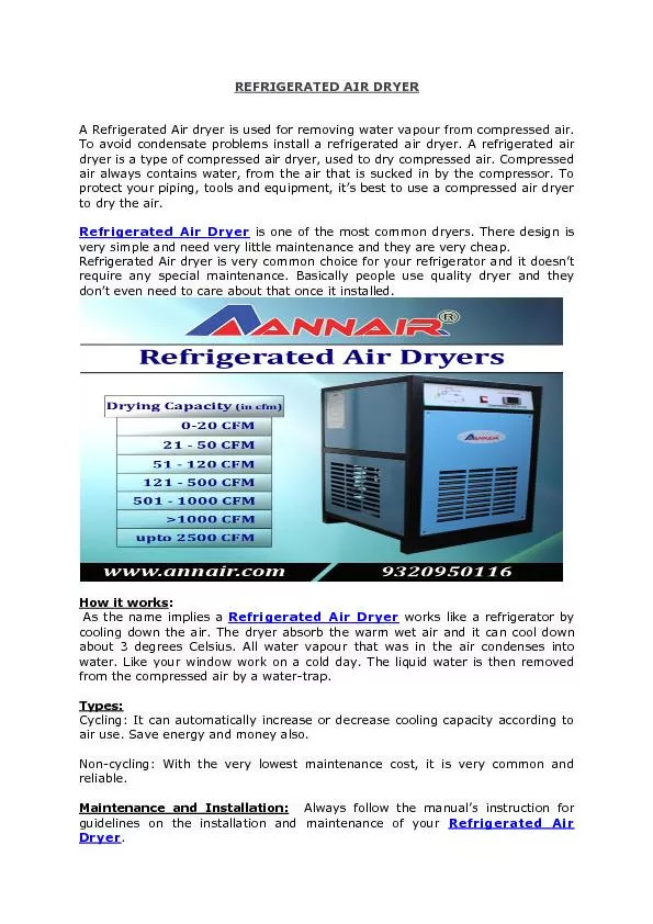
Derek Clark PSE Josh Jordan PSE Ken Figueiredo CpE To have a secure channel to transfer data Rugged and reliable Send data over land that you dont own Immune to Electromagnetic interference ID: 618635
Download Presentation The PPT/PDF document "The LDT-AIR Project" is the property of its rightful owner. Permission is granted to download and print the materials on this web site for personal, non-commercial use only, and to display it on your personal computer provided you do not modify the materials and that you retain all copyright notices contained in the materials. By downloading content from our website, you accept the terms of this agreement.
Slide1
The LDT-AIR Project
Derek Clark (PSE)Josh Jordan (PSE)Ken Figueiredo (CpE)Slide2
To have a secure channel to transfer data
Rugged and reliable.Send data over land that you don’t own.Immune to Electromagnetic interference.Cheaper hassle-free alternative conventional wire/fiber.MotivationSlide3
Requirements:
At least a 1Mbps connection speed with less than a 15% error rate.Be able to create a connection over a distance of 15 feet.Goals:Reach a transfer speed on par with Wi-Fi (54Mbps – 600Mbps)Be able to create a connection greater 30 feet.
A bit error rate of zero.
Requirements & GoalsSlide4
Speeds comparable to Wi-Fi (54Mbps).
Transmit and receive data >15ft.Send text messages, files, music and video.Project SpecificationsSlide5
Block DiagramSlide6
Transmitter Housing Slide7
Single Mode Fiber
Multi-Mode FiberExpensive
Less expensive
Smaller Numerical Aperture
Larger Numerica
l Aperture
Lower
Dispersion
Higher Dispersion and
attenuation
Fiber PigtailSlide8
Pigtail laser package comes with FC/PC adapter.
Coupling loss is associated with adapters.Replaced with SM adapter.Makes alignment of the system easier.Allows for troubleshooting. laser is bad.
Laser Fiber ConnectorSlide9
Lens HousingSlide10
Lens Type
Plano-convex lens with no AR coating.
Focal length at 25mm.
Designed specifically for 1550nm wavelength.
Associated lens holder was incorporated to make fastening easy.Slide11
PowerSlide12
Supply Current
Seller
Supply Voltage
Number of Adapters
Cost
$
NA
1000mA
Skycraft
2-12V
6 plugs
$9.99
Original Power Powerline
1300mA
Walmart
3-12V
7 Plugs
$11.65
Velleman PSSMV1USA
1500mA
Amazon
3-12V
8 Plugs
$14.99
Enercell
1000mA
Radioshack
3-12V
0 Plugs
$19.99
AC/DC Regulator ComparisonSlide13
Components
Bill of Materials Cost
Efficiency
Frequency
Temperature
TPS62122
7
$0.68
72%
874kHz
35°C
TPS62120
8
$0.69
72%
874kHz
35°C
TPS563200
7
$0.89
84%
78kHz
31°C
3.3V Regulator ComparisonSlide14
3.3V Regulator CircuitSlide15
Components
Bill of materials
Efficiency
BOD
Footprint
TSP62153
6
$1.17
94%
80
TPS562209
8
$0.82
94%
112
TPS563209
8
$1.37
95%
116
5V Regulator Comparison
TSP62153 was easy to incorporate.
Smaller in design.Slide16
5V Regulator CircuitSlide17
STM32F746NGH6
Operating Voltage: 1.8V - 3.6V
ARM 32bit Cortex – M7 core
Pros:
216 MHz clock speed
108 MHz GPIO speed
Allows for Ethernet PHY connectivity.
Cons:
Difficult to program, limited documentation
Base software has large overhead.
216 ball grid array pin out
10mm
10mmSlide18
STM32F7 - Discovery
Evaluation board for the STM324746NG microcontroller
Pros:
Has all connections already completed
Allows for quicker prototyping
Cons:
Same as microcontroller.
Official ARM compiler does not fully support all features of the board.
Specifically: Ethernet, USB 2.0, USB 3.0 Slide19
Easier to implement than USB with the chosen microcontroller.
Less overhead than the USB 3.0 connector.Ethernet protocol utilizes FreeRTOS which allows threading within board software.
PC Connection : EthernetSlide20
Signal is created by turning a GPIO pin on / off dependent on the data received from the PC.
The transmission signal uses two different time delays for ease of framing the packets.Bit delay, Time between each bit. Determines output frequency.Frame delay, Time between each frame. (
bitDelay
* 2)
Syncing the transmitter and receiver
Signal modulationSlide21
Syncing the transmitter and receiver
Signal modulationSlide22
Software breakdownSlide23
Transmitter code structureSlide24
Receiver code structureSlide25
Error handling
Packet Loss
Signal InterferenceSlide26
Selected 1550nm wavelength.
Standard in Telecommunication.Safe operating wavelength.Sunlight spectrum will not interfere with the photodetector.Laser WavelengthSlide27
Wavelength Range (nm)
Operating Voltage (V)
Threshold Current
(mA)
Output Power CW (
mW
)
Pulse Width
(ns)
Price
$
Diode Only Quantum Well Laser
Panasonic LNCT28PF01WW
656-665
2.4
50
100
30
15.62
Panasonic LNCT22PK01WW
777-791
2.5
45
200
100
15.62
Diode Only Vertical Cavity Surface Emitting Laser
TT Electronics OPV300
860
2.2
3
1.5
.2
14.65
TT Electronics OPV314AT
860
2.2
3
.6
.210
20.50
Pigtail Package Quantum Well Laser
US-Lasers MM850-0
840-860
2.4
20
5
-
76.0
Renesas
NX7338BF-AA
1310
2.5
20
10
4
266.0
Renesas
NX7538BF-AA
1550
2.5
45
10
4
285.95
14 Pin Butterfly Package Quantum Well Laser
Mitsubishi FU-68SDF-V802M
1550
1.8
10
6
.150
148.50
Laser ComparisonSlide28
Small, and flexible design.
Easy to implement with lens design.Laser PackageSlide29
Supply Voltage (V)
Min Bias Current
(mA)
Packaging Configuration
Data Rates
(
Gbps
)
Pulse Width
(
ps
)
Price
$
Texas Instruments
ONET1101L
3.3
5
QFN Package
2-11.3
60
Sample
Mindspeed
M02067
3.3
4
Tray
up to 2.1
<150
8.50
Philips
TZA3047A
3.3
5
BCG
.030-1.25
300
10
Texas Instruments
ONET4201L
3.3
5
QFN Package
.155-4
60
Sample
MAX3736
3.3
5
QFN Package
4Gbps
90
3.50
Laser Driver ComparisonSlide30
Laser Driver CircuitSlide31
Thorlabs FGA01 ($56.70)
InGaAs materialWavelength range: 800 - 1700 nmResponsitivity: 1.003 A/WNEP@1550nm,20V: 4.5x10^-15W/HzReverse Bias: 20V (max)Dark Current: 0.05 nA, 2 nA (max
)
PhotodetectorSlide32
Photovoltaic
solar cellPhotoconductivephotodetector
Operation ModeSlide33
Prototype circuit using IR LEDs
2 Mbps max rate ATMEGA2560Radioshack parts ($3.99).
Photodetector CircuitSlide34
AD744
Cost: $1.00Cerdip (Q) packageDimensions: in. (mm).13 MHz gain bandwidth
Operational AmplifierSlide35
OP27EP
Cost: $2.00Cerdip (Q) packageDimensions: in. (mm).8 MHz gain bandwidth
Operational AmplifierSlide36
Operational Amplifier CircuitSlide37
Receiver Voltage RegulatorSlide38
Small active area diameter: 0.12 mm
Beam DispersionAtmospheric Absorption
Receiver issuesSlide39
Ball Lens
0.06” diameterIn door experiments
AccommodationsSlide40
Amt.
Cost
Infrared emitter & detector
x1
$ 9.99
Thorlabs
FGA01
x1
$ 56.70
Mitsubishi
Laser FU-68sdf-v802m
x1
$ 148.50
opamps
x2
$3.00
Circuit Board
x1
$4.00
Inductor
Kit
x1
$ 14.44
Capacitor Kit
x1
$ 14.00
Laser Driver
x3
$ 3.57 (free)
Transimpedance
Amplifier
x2
$ 7.85 (free)
Dip
Adapter
x3
$15.00
AC
– DC converter
x2
$10.00
Heat Sink
x1$4.95Budget Slide41
Coaxial Cable
12 feet
$2.50
Lens
x1
$24.30
Lens Housing
x1
$15.23
Hardware for lens
NA
$5.31
Hardware for Electric
circuit
NA
$33.55
2.1mm
PowerJack
x1
$0.75
Lexan Sheet
x1
$60.00
Brackets/Bolts/Nuts
NA
$6.00
Perforated
Circuit Board
x1
$6.99
STM32F746
Discovery Board
x2
$100.00
Infrared Card
X1
$73.00
Total:
$624.75
Allotted
Budget:
$500.00Budget Cont.Slide42
Transmitter
Receiver
Microcontroller
Power System
Derek
P
S
S
P
Josh
S
P
S
S
Ken
P
S
Work DistributionSlide43
Temporary network in case of disaster
Satellite / Aircraft communicationLIDARCan send data over multiple laser beams to one photodetector.Temporary network in case of a disaster.Future ApplicationsSlide44
Successes and DifficultiesSlide45
Questions?