/
Status of  Linac  High Voltage Converter Modulator Upgrades Status of  Linac  High Voltage Converter Modulator Upgrades

Status of Linac High Voltage Converter Modulator Upgrades - PowerPoint Presentation

2coolprecise
2coolprecise . @2coolprecise
Follow
348 views
Uploaded On 2020-08-29

Status of Linac High Voltage Converter Modulator Upgrades - PPT Presentation

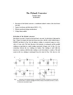
Accelerator Advisory Committee Review David E Anderson High Voltage amp Pulsed Power Systems Research Accelerator Division February 2016 Modulators provide pulsed power to high power RF klystrons using 20 kHz switching with IGBTs ID: 811689

hvcm power pulse operation power hvcm operation pulse igbt test ripple additional modulators modulator voltage klystrons installed scl output

Share:

Link:

Embed:

Download Presentation from below link

Download The PPT/PDF document "Status of Linac High Voltage Converter..." is the property of its rightful owner. Permission is granted to download and print the materials on this web site for personal, non-commercial use only, and to display it on your personal computer provided you do not modify the materials and that you retain all copyright notices contained in the materials. By downloading content from our website, you accept the terms of this agreement.


Presentation Transcript

Slide1

Status of Linac High Voltage Converter Modulator Upgrades

Accelerator Advisory Committee Review

David E. Anderson, High Voltage & Pulsed Power Systems

Research Accelerator Division

February 2016

Slide2

Modulators provide pulsed power to high power RF klystrons using 20 kHz switching with IGBTs

Provides up to 135 kV, 1.35

ms

pulses at 60 Hz to amplify RF to 5 MW

3 phases employed to increase output ripple frequency

Minimizes output filter requirements

Minimizes fault energy available to klystron

Powers multiple klystrons up to 11 MW peak power

Currently there is ≤5% pulse droop operating in open-loop

Slide3

15 Modulators in 3 different configurations power 92 klystrons to support operation of the

Linac

15 modulators: 3 - DTL, 4 - CCL, 8

– SCL (1 added 2008)

Multiple HVCM/Klystron

Configurations

Approx. 1×10

6

combined operational hours on all modulators

115 kV

125 kV

≤135 kV

71 kV

75 kV

DTL (8.5-10.6 MW peak)

CCL (8.4-9.1 MW peak)

SCL (8.0-8.8 MW peak)

Slide4

Despite numerous short duration trips, the HVCM systems’ downtime is dominated by >4 hour events

Initiated 12-18 month boost capacitor replacement campaign

HVCM Number of Events by Duration

Slide5

Analysis of failures by major component & subsystems is critical to improving overall system availability

Downtime

Hours

Feb-Jun 2012

Aug-Dec 2012

Jan-May 2013

Aug-Dec 2013

Feb-Jun 2014

Aug-Dec 2014

Jan-Jun 2015

Aug-Dec 2015

Σ Hours

Scheduled

Beam Hours

3130

1868

3355

2789

3331

3105

3458

3037

24,073

Boost Capacitor

36.9

11.4

27.7

10.4

-

-

-

86.4

IGBT/driver

5.0

-

-

-

13.0

-

28.1

5.0

51.1

SCR Hardware

22.8

-

-

-

17.9

-

-

40.7

Controller / PLC

-

20.9

-6.5-8.2-35.6Mod. Tank-20.0----5.725.7SCR Controls-3.0---7.3-10.3Control Cables-4.06.0---8.53.922.4Water Panel-8.0-----8.0Ctrl. Electronics--4.5-9.0-2.415.9Oil Pump-7.1--7.7--10.124.9Miscellaneous0.5-4.418.30.113.82.77.347.1Σ65.274.442.635.247.729.347.426.3368.1(1.5%)

Initiated 12-18 month boost capacitor replacement campaign

Slide6

A key vulnerability to continuing reliable operation are the NCL HVCM boost capacitors

Condenser Products currently utilized in all systems but have exhibited some problems

Case cracking and thermal fluid degradation

Weld and material tested to 65°C

Cargill says no chemical interaction w/ FR3 based on their analysis

Current

strategy is to replace

NCL every

12-18 months

Hardware costs ~$

50k (NCL only)

Effort ~2 days each × 7 units

(~$30k)

Completed during winter 2015/2016 outage

NWL capacitors currently under evaluation in CCL-Mod1 (~4000 hrs. operation) and NWL will deliver a thermally-instrumented unit in March

Investigate alternate capacitor designs / technologies

TPC solution shown is metallized poly, also permits tuning of resonant circuit

Under test now in RFTF

Slide7

New IGBT gate driver circuits improve reliability, lower losses, enhance IGBT protection and reduce ripple

Currently installed on all systems

Demonstrated IGBT switching loss reduction of 30%

Provides protection for IGBT / driver issues

Modular and

connectorized for ease-of-maintenance

~5X reduction in RF forward power ripple

BEFORE

AFTER

Forward Power

Forward Power

Slide8

Adding IGBT snubbers permits higher voltage operation, reliable higher current IGBT operation & eliminates fault over-voltage problem

Installed on 12 of 15 operational modulators, 2 test stands

Combined

>

100,000 operational hours w/ no issues

Necessary for reliable pulse flattening and improved IGBT reliability

Slide9

2 additional

m

odulators plus a partial system are available to support modulator development and testing activities

RFTF HVCM

NCL variant of HVCM

Primarily to support RF- and

cryo module testing, ISTF (new RFQ)

Secondary mission is NCL HVCM work

Extended run testing

HEBT HVCM

SCL variant of HVCM, STS-rated beam stick load

Dedicated mission is to support HVCM testing

Most development work is initiated here

Open frame test stand

Prototype efforts

Alternate topology

Laminated bus

Affords flexibility and more extensive instrumentation @ limited power levels

Single Phase Test Stand (not shown)

Useful to test IGBT assemblies for matched timing on all 4 IGBTs and pre-qualification of spares

Slide10

Pulse flattening to achieve reliable 1.4 MW operation, provide additional LLRF control margin and support PPU

Klystrons are at saturation at the end of the pulse with no remaining control margin

Pulse flattening for improved LLRF control margin demonstrated

and currently running on DTL-Mod5, SCL-Mod18 and test modulators

Utilizing frequency modulation

Comparable LLRF regulation error

IGBT commutation currents increase by 40% but still acceptable

SCL-Mod18 Output Voltage with 17.8 to 23.0 kHz frequency modulation

18.5 – 23.0 kHz sweep with

vernier

Slide11

The new controller supports the proposed modulation scheme and can provide additional functionality (AIP-34)

First Fault detection

Pulse Flattening

Full waveform capture

Commercial platform-based

Additional operational modes

Enhanced IGBT functionality integrated

Intellectual property ownership

Installed in test stands 2013

Installed in Summer 2014 in 1 SCL HVCM

Installed Winter 2015 in 1 DTL, 1 CCL, 1 SCL HVCMs

Slide12

Enhanced reliability and reduced MTTR is improved by replacing the existing oil cooling system (AIP-36)

System/Operation Improvements

:

Filter can be swapped during operation w/o interruption

Pump/motor assembly can be changed without removing the tank

Internal surface temperatures have dropped

by at least 45 °

F

Oil turnover and filtering has improved more than 3X and flow does not decrease during operation

The Barron’s Oil system can be used during operation

Will be adding dissolved gas analyzer (H

2

, CO, C

2

H

2

, & C2H

4 (ethylene))

Design Model of Internal Piping

Design Model of Pump Ass’y.

Slide13

1st Article measurements indicate substantial improvements in component and oil temperature

Thermal/Hydraulic Improvements

:

Overall the bulk oil temperature to the HX has dropped from greater than 118°F to 102°F

Overall heat removal to the cooling water has increase more than 300%

Internal surface temperatures have dropped from 108°/185°F to 101°/145°F

Oil turnover and filtering has improved more than 3X and flow does not decrease during operation

Slide14

The Alternate Topology Modulator (ATM) shows promise for PPU and other applications

Presently installed in HEBT test stand.

Delivering 1.2ms 70kV 100A pulse at 60 Hz.

92% efficient ZVS/ZCS power conversion.

Thermal run completed. Maximum temperatures recorded transformer (76

°C), rectifier (

72 °C) and resonant capacitor (39

°C) are well within safe operating margins.Plan to operate at levels required for PPU after verifying safe for beam stick loads (shorted wire test)

Fixed frequency operation: output regulation 0.7% pp presently limited by phase to phase imbalance in resonant tank components.

Variable frequency operation: 24kHz-19kHz sweep illustrating pulse flattening capability

AØ,BØ,CØ XFMR Primary Currents

AØ,BØ,CØ

XFMR

Primary Currents

Mod Vout ripple (~1.3%)

Mod Vout

ripple detail

1.2ms pulse

1.2ms pulse

Slide15

The laminated bus promises lower ripple and reduced MTTR for switch plates

Inductance of header cables, creating a substantial ripple on the switch plate DC bus. The ringing appears at the output and requires additional filtering.

Excessive DC ripple adds additional voltage stress to the IGBTs

Laminated bus reduces inductance and permits removal of most bypass capacitors

0.7% ripple demonstrated (on alternate topology) vs. several percent with current cable system

Slide16

The PPU Project requires some development but should achieve comparable reliability

Modify boost transformers in warm

linac

to achieve required higher output voltages, esp. for 3.0 MW klystrons

Existing

medium/high beta cavity klystron:modulator ratio of 10:1 forces higher DC bus voltage

for additional power

Reduction to a 9:1

klystron:modulator

ratio for

first 18 new

cavities (2 HVCMs), 10:1 ratio for the

last 10 new

cavities at reduced power levels

3 additional modulators required for PPU upgrade

HVCM Considerations for PPU with 3.0 MW Klystrons in DTL4

and DTL5 Locations

Slide17

The JEMA modulator tested and awaiting controls upgrades to perform 30-day continuous test

Operated at peak available output power (90 kV, 38 A, 340 kW peak) at extended pulse width (3.5

ms

) to achieve ~750 kW average power operationUpgrading controls to accommodate CO2 discharge, smoke detectors and other equipment-protection systems for unattended 24/7 30-day testFuture applications under negotiation with ESS-BilbaoCan power up to 12 700 kW CPI klystrons (STS power levels)

Slide18

20KHz @ Start of Pulse & 21.2KHz @ End

Summary

HVCM availability improved substantially and meets facility availability requirements

Synergistic solutions in development or installed to address remaining problems with HVCM to further improve reliability, increase available power and flatten pulse

Shift focus to concentrate on ripple to improve RF regulation error

Capacitor problems continue but multiple options being evaluated

Implementation of proposed alternate topology allows for future expansion & major subsystem redundancy

The SNS modulator team and the demonstrated HVCM high availability makes this topology attractive to KAERI and the proposed

MaRIE

upgrade

Other modulators (JEMA) being evaluated internally for future applications.