/
LVAD System Review System Overview LVAD System Review System Overview

LVAD System Review System Overview - PowerPoint Presentation

CantTouchThis
CantTouchThis . @CantTouchThis
Follow
344 views
Uploaded On 2022-07-28

LVAD System Review System Overview - PPT Presentation

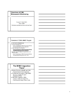
Smiha Sayal System Overview Left Ventricular Assist Device LVAD Mechanical device that helps pump blood from the heart to the rest of the body Implanted in patients with heart diseases ID: 929865

electronics system internal control system electronics control internal embedded water housing option components astm body lvad external material device

Share:

Link:

Embed:

Download Presentation from below link

Download Presentation The PPT/PDF document "LVAD System Review System Overview" is the property of its rightful owner. Permission is granted to download and print the materials on this web site for personal, non-commercial use only, and to display it on your personal computer provided you do not modify the materials and that you retain all copyright notices contained in the materials. By downloading content from our website, you accept the terms of this agreement.


Presentation Transcript

Slide1

LVAD System Review

Slide2

System Overview

Smiha

Sayal

Slide3

System Overview

Left Ventricular Assist Device

(LVAD)

Mechanical device that helps pump blood from the heart to the rest of the body.

Implanted in patients with heart diseases or poor heart function.

Slide4

System Goal

Miniaturize

the existing LVAD system to achieve

portability

while retaining its safety and reliability.

Slide5

Engineering Process

All team members

Slide6

Customer Needs

Safe

Robust

Affordable

Easy to wear and use

Interactive with user

Controllable by skilled technician

Comparable performance

Compatible with existing pump

Slide7

Other LVAD Technologies

CorAide

(NASA)

Slide8

Other LVAD Technologies

Slide9

Original System

“Black box” architecture used during development

Large, not portable

Runs on AC power

Slide10

P10021’s System

Has both internal / external components

Equivalent to our “Option 2”

Unfinished implementation

Slide11

Concepts: Option 1

All electronics external

Slide12

Concepts: Option 2

ADC internal only

Slide13

Concepts: Option 3

Pump and motor control internal

Slide14

Concepts: Option 4

All electronics and battery internal

Slide15

Concept Generation

Slide16

Concept Generation Highlights

Best Option

350

273

200

153

Slide17

Enclosure Design

Nicole

Varble

and Jason

Walzer

Slide18

Material and Processing Selection

Needs

The external package should be lightweight/ robust/ water resistant

The devices should be competitive with current devices

The device should fit into a small pouch and be comfortable for user

Specification

Optimum weight of 5 lbs

Optimum dimensions of ~6” x 2” x 2”

Risks

Housing for the electronics is too heavy/large/uncomfortable

Preventative measures

Eliminate heavy weight materials

Eliminate weak, flexible materials

Material is ideally

machinable

Slide19

Material and Processing Comparison

Slide20

Rapid Prototyping

Dimension System

ABSplus

Industrial thermoplastic

Typically used for product developmentMachinable

Material can be dilled (carefully) and tapped

Accepts CAD drawings

Obscure geometries can be created easily

Ideal for proposed ergonomic shape

Lightweight

Specific gravity of 1.04

Porous

Does not address water resistant need

0.007” material/layer

Capable of building thin geometries

Builds with support layer

Models can be built with working/moving hinges without having to worry about pins

http://www.dimensionprinting.com/

Slide21

ABS Plastic

Mechanical Property

Test Method

Imperial

Metric

Tensile Strength

ASTM D638

5,300 psi

37

MPa

Tensile Modulus

ASTM D638

330,000 psi

2,320

MPa

Tensile Elongation

ASTM D638

3%

3%

Heat Deflection

ASTM D648

204°F

96°C

Glass Transition

DMA

(SSYS)

226°F

108°C

Specific Gravity

ASTM D792

1.04

1.04

Coefficient

of Thermal Expansion

ASTM E831

4.90E-5 in/in/F

Important

Notes

Relatively high tensile strength

Glass

Transition well above body temperature

Specific Gravity indicates lightweight material

Slide22

Water Resistant Testing

Need: The external package should resist minor splashing

Specification: Water Ingress Tests

Once model is constructed, (user interface, connectors sealed, lid in place) exclude internal electronics and perform test

Monitor flow rate (length of time and volume) of water

Asses the quality to which water is prevented from entering case

Risk: Water can enter the external package and harm the electronics

Preventative measures:

Spray on Rubber Coating or adhesive

O-rings around each screw well and around the lid

Loctite

at connectors

http://scoutparts.com/products/?view=product&product_id=14074

Slide23

Robustness Testing

Need

: The device should survive a fall from the hip

Specification

: Drop TestDrop external housing 3-5 times from hip height, device should remain fully intactSpecify and build internal electrical components

Identify the “most venerable” electrical component(s) which may be susceptible to breaking upon a drop

Mimic those components using comparable (but inexpensive and replaceable) electrical components

Goal

Show the housing will not fail

Show electronics package will not fail, when subjected to multiple drop tests

Risks

The housing fails before the electronic components in drop tests

The electronic components can not survive multiple drop tests

Preventative Measures

Eliminate snap hinges from housing (screw wells to secure lid)

Test the housing first

Take careful consideration when developing a thickness of the geometry

Design a “tight” electronics package

Slide24

Heat Dissipation to the Body

Need: Internal Enclosure dissipates a safe amount of heat to the body

Risk: Internal electronics emit unsafe amounts of heat to body

Benchmarking:

Series of tests studied constant power density heat sources related to artificial hearts60-mW sources altered surface temperatures 4.5, 3.4, 1.8 °C above normal at 2, 4, 7 weeks

40mW/cm

2

source increased to upper limit of 1.8 °C

Specifications: Internal devices must not increase surrounding tissue by more than 2°C


Wolf, Patrick D. "Thermal Considerations for the Design of an Implanted Cortical Brain–Machine Interface (BMI)."

Ncib.gov

. National Center for Biotechnology Information, 2008. Web. 30 Sept. 2010. <http://www.ncbi.nlm.nih.gov/bookshelf/br.fcgi?book=frimp∂=ch3>.

Slide25

Ergonomics

Need

: Device should be comfortable for user

ANSUR Database

Exhaustive military database outlining body dimensions

Waist Circumference (114)

Males: 137.3 mm

Females: 126.0 mm

Waist Depth (115)

Males: 113.1 mm

Females: 102 mm

Calculated average radius of hip

Males: 125.2 mm

Females: 114.0 mm

Acceptable Avg. Radius of hip

~120 mm

Slide26

Enclosure Concept

CAD model is can be easily resized

Removable top panel for electronics access

Slide27

Embedded Control System

Andrew Hoag and Zack Shivers

Slide28

Control System

Requirements

Selecting suitable embedded control system

Designing port of control logic to embedded system architecture

Customer NeedsDevice is compatible with current LVADDevice is portable/smallAllows debug access

Slide29

Impeller Levitation

Impeller must be

levitating

or “floating”

Electromagnets control force exerted on impeller

Keeps impeller

stabilized

in the

center

Position error measured by

Hall Effect

sensors

Slide30

Levitation Algorithm

Algorithm

complexity

influences microcontroller choice

Electronics choices affect volume / weightProportional – Integral – Derivative (PID)Very common, low complexity control scheme

http://en.wikipedia.org/wiki/PID_controller

Slide31

Embedded System Selection

Requirements:

Can handle

PID

calculationsHas at least 8x 12-bit ADC for sensors at 2000 samples/sec

Multiple

PWM

outputs to motor controller(s)

Same control logic as

current

LVAD system

Reprogrammable

Slide32

Embedded System Selection

Custom Embedded

dsPIC

Microcontroller

Blocks for

Simulink

Small

Inexpensive (<$10 a piece)

TI MSP430

Inexpensive (<$8 a piece)

Small, low power

COTS Embedded

National Instruments Embedded

Uses

LabVIEW

Manufacturer of current test and data acquisition system in “Big Black Box”

Large to very large

Very expensive (>$2000)

Slide33

Control Logic/Software

Closed-loop feedback

control using PID – currently modeled in

Simulink

for use with the in “Big Black Box”Additional

microcontroller-specific

software will be required to configure and use A/D, interrupts, timers.

Slide34

Life Critical System

Not at

subsystem

level detail yet.

Life-critical

operations would run on main microcontroller.

User-interface

operations run on separate microcontroller.

Possible

LRU

(Least Replaceable Unit) scheme

Slide35

Questions / Comments

Help us improve our design!