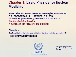
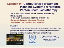
/
Objective:   To familiarize the student with the Objective:   To familiarize the student with the

Objective: To familiarize the student with the - PowerPoint Presentation

PeacefulPlace
PeacefulPlace . @PeacefulPlace
Follow
342 views
Uploaded On 2022-08-04

Objective: To familiarize the student with the - PPT Presentation

general principles particular procedures and quality assurance of computerized treatment planning systems including hardware and software Chapter 11 Computerized Treatment Planning Systems for External Photon Beam Radiotherapy ID: 934767

oncology radiation physics review radiation oncology review physics slide students handbook teachers beam system dose calculation data algorithms software

Share:

Link:

Embed:

Download Presentation from below link

Download Presentation The PPT/PDF document "Objective: To familiarize the student ..." is the property of its rightful owner. Permission is granted to download and print the materials on this web site for personal, non-commercial use only, and to display it on your personal computer provided you do not modify the materials and that you retain all copyright notices contained in the materials. By downloading content from our website, you accept the terms of this agreement.


Presentation Transcript

Slide1

Objective: To familiarize the student with the general principles, particular procedures and quality assurance of computerized treatment planning systems including hardware and software.

Chapter 11: Computerized Treatment Planning Systems for External Photon Beam Radiotherapy

Set of 117 slides based on the chapter authored byM.D.C. Evans of the IAEA publication (ISBN 92-0-107304-6):Review of Radiation Oncology Physics: A Handbook for Teachers and Students

Slide set prepared in 2006

by G.H. Hartmann (Heidelberg, DKFZ)

Comments to S. Vatnitsky:

dosimetry@iaea.org

Slide2

Review of Radiation Oncology Physics: A Handbook for Teachers and Students - 11.Slide 111.1 Introduction

11.2 System Hardware11.3 System Software and Calculations Algorithms11.4 Commissioning and Quality Assurance11.5 Special ConsiderationsCHAPTER 11. TABLE OF CONTENTS

Slide3

Review of Radiation Oncology Physics: A Handbook for Teachers and Students - 11.1 Slide 111.1 INTRODUCTION

Radiation treatment planning represents a major part of the overall treatment process.Treatment planning consists of many steps including patient diagnostic, tumor staging, image acquisition for treatment planning, the localization of tumor and healthy tissue volumes, optimal beam placement, and treatment simulation and optimization.A schematic overview also showing the associated quality assurance activities is given on the next slide.

Slide4

Review of Radiation Oncology Physics: A Handbook for Teachers and Students - 11.1 Slide 2

Steps of the treatment planning process, the professionals involved in each step and the QA activities associated with these steps (IAEA TRS 430)

TPS related activity

11.1 INTRODUCTION

Slide5

Review of Radiation Oncology Physics: A Handbook for Teachers and Students - 11.1 Slide 3This chapter deals explicitly with that component of the treatment planning process that makes use of the computer.

Computerized Treatment Planning Systems (TPS) are used in external beam radiation therapy to generate beam shapes and dose distributions with the intent to maximize tumor control and minimize normal tissue complications. 11.1 INTRODUCTION

Slide6

Review of Radiation Oncology Physics: A Handbook for Teachers and Students - 11.1 Slide 4Treatment planning prior to the 1970s was generally carried out through the manual manipulation of standard isodose charts onto patient body contours that were generated by direct tracing or lead-wire representation, and relied heavily on the judicious choice of beam weight and wedging by an experienced

dosimetrist. 11.1 INTRODUCTION

Slide7

Review of Radiation Oncology Physics: A Handbook for Teachers and Students - 11.1 Slide 4Simultaneous development of computerized tomography, along with the advent

of readily accessible computing power from the 1970s on, lead to the development of CT-based computerized treatment planning, providing the ability to view dose distributions directly superimposed upon patient’s axial anatomy.

11.1 INTRODUCTION

Slide8

Review of Radiation Oncology Physics: A Handbook for Teachers and Students - 11.1 Slide 5Advanced TPS are now able to represent patient anatomy, tumor targets and even dose distributions as three dimensional models.

Clinical target volume, both lungs, and spinal chord, as seen from behind (ICRU 50).

11.1 INTRODUCTION

Slide9

Review of Radiation Oncology Physics: A Handbook for Teachers and Students - 11.1 Slide 6Successive improvements in treatment planning hard-ware

and software have been most notable in the graphics, calculation and optimization aspects of current systems.Systems encompassing the “virtual patient” are able to display: Beams-Eye Views (BEV)of patient's anatomyDigitally Reconstructed

Radiographs (DRR)

brain stem

tumor

eyes

optic

nerves

11.1 INTRODUCTION

Slide10

Review of Radiation Oncology Physics: A Handbook for Teachers and Students - 11.1 Slide 7Dose calculations have evolved from simple 2D models through 3D models to 3D Monte-Carlo techniques, and increased computing power continues to increase the calculation speed.

Monte Carlo simulation of an electron beam produced in the accelerator head

11.1 INTRODUCTION

Slide11

Review of Radiation Oncology Physics: A Handbook for Teachers and Students - 11.1 Slide 8Computerized treatment planning is a rapidly evolving modality, relying heavily on both hardware and software.

As such it is necessary for related professionals to develop a workable Quality Assurance (QA) program that reflects the use of the TP system in the clinic, and is sufficiently broad in scope to ensure proper treatment delivery. 11.1 INTRODUCTION

Slide12

Review of Radiation Oncology Physics: A Handbook for Teachers and Students - 11.2 Slide 111.2 SYSTEM HARDWARE

In the 1970s and 1980s treatment planning computers became readily available to individual radiation therapy centers. As computer hardware technology evolved and became more compact so did Treatment Planning Systems (TPS).

Principal hardware components are described in the following slides.

Slide13

Review of Radiation Oncology Physics: A Handbook for Teachers and Students - 11.2.1 Slide 111.2 SYSTEM HARDWARE

11.2.1 Treatment planning system hardwarePrincipal hardware components of a Treatment Planning (TP) system:Central Processing Unit (CPU)

Graphics displayMemoryDigitizing devicesOutput devicesArchiving and network communication devices

Slide14

Review of Radiation Oncology Physics: A Handbook for Teachers and Students - 11.2.1 Slide 2Principal hardware components of a TP system:

1. Central Processing Unit Central Processing Unit must have Sufficient memory

Sufficient high processor speed as required by the operating system and the treatment planning software to run the software efficiently.

Therefore, in the purchase phase the specifications for the system speed, Random Access Memory (RAM) and free memory, as well as networking capabilities must be carefully considered.

11.2 SYSTEM HARDWARE

11.2.1 Treatment planning system hardware

Slide15

Review of Radiation Oncology Physics: A Handbook for Teachers and Students - 11.2.1 Slide 311.2 SYSTEM HARDWARE

11.2.1 Treatment planning system hardwarePrincipal hardware components of a TP system:2. Graphics display

Graphics display be capable of rapidly displaying high resolution images.Graphics speed can be enhanced with video cards and hardware drivers (graphics processor).Resolution is sub-millimeter or better so as not to distort the input.Graphics display should be sufficient for accommodating the patient transverse anatomy on a 1:1 scale, typically 17 to 21 inches (43 to 53 cm) or larger

.

Slide16

Review of Radiation Oncology Physics: A Handbook for Teachers and Students - 11.2.1 Slide 411.2 SYSTEM HARDWARE

11.2.1 Treatment planning system hardwarePrincipal hardware components of a TP system:2. Graphics display

(cont.)

Slide17

Review of Radiation Oncology Physics: A Handbook for Teachers and Students - 11.2.1 Slide 511.2 SYSTEM HARDWARE

11.2.1 Treatment planning system hardwarePrincipal hardware components of a TP system:3. Memory

Memory and archiving functions are carried through a) Removable media:

Re-writable hard-disksOptical disksDVDs

DAT tape

Attention

:

These

devices have been reported to suffer from

long term instability.

Slide18

Review of Radiation Oncology Physics: A Handbook for Teachers and Students - 11.2.1 Slide 611.2 SYSTEM HARDWARE

11.2.1 Treatment planning system hardwarePrincipal hardware components of a TP system:3. Memory (cont.)

Memory and archiving functions are carried out through b) Network on:Remote computer S

erverLinac with its record-and-verify system

Archiving

operations may be carried out automatically during low use periods of the day.

Slide19

Review of Radiation Oncology Physics: A Handbook for Teachers and Students - 11.2.1 Slide 711.2 SYSTEM HARDWARE

11.2.1 Treatment planning system hardwarePrincipal hardware components of a TP system:4. Digitizing devices

Digitizing devices are used to acquire manually entered patient data such as transverse contours and beams-eye-views of irregular field shapes.Methods:Backlit tablets with stylus for manually tracing shapes.Scanners to digitize images from hardcopy such as paper or radiographic film.Video frame

grabbers.

Slide20

Review of Radiation Oncology Physics: A Handbook for Teachers and Students - 11.2.1 Slide 811.2 SYSTEM HARDWARE

11.2.1 Treatment planning system hardwarePrincipal hardware components of a TP system:4. Digitizing devices (cont.)

Slide21

Review of Radiation Oncology Physics: A Handbook for Teachers and Students - 11.2.1 Slide 911.2 SYSTEM HARDWARE

11.2.1 Treatment planning system hardwarePrincipal hardware components of a TP system:5. Output

devices Output devices include color laser printers and plotters for text and graphics. Printers and plotters can be networked for shared access.

Hardcopy can be to paper or to film via a laser camera.Uninterruptible Power Supplies (UPS).

Slide22

Review of Radiation Oncology Physics: A Handbook for Teachers and Students - 11.2.1 Slide 1011.2 SYSTEM HARDWARE

11.2.1 Treatment planning system hardwarePrincipal hardware components of a TP system:5. Output

devices (cont.) Uninterruptible Power Supplies (UPS) are recommended for the CPU, data servers, and other critical devices such as those used for storage and archiving. UPSs can provide back-up power so that a proper shut-down of the computer can be accomplished during power failures from the regular power distribution grid, and they also act as surge suppressors for the power.

Slide23

Review of Radiation Oncology Physics: A Handbook for Teachers and Students - 11.2.1 Slide 1111.2 SYSTEM HARDWARE

11.2.1 Treatment planning system hardware Principal hardware components of a TP system:6. Communications hardware

Communications hardware includes modem or ethernet cards on the local workstations and multiple hubs for linking various peripheral devices and workstations. Large networks require fast switches running at least 100 MB/s for file transfer associated with images. Physical connections on both small and large networks are run through coaxial cable, twisted pair or optical fiber depending upon speed requirements

.

Slide24

Review of Radiation Oncology Physics: A Handbook for Teachers and Students - 11.2.2 Slide 1211.2 SYSTEM HARDWARE

11.2.2 Treatment planning system configurations TP hardware systems can be classified intoSmaller TP system configurations for only a few usersStand-alone lay-out and archiving.

One central CPU for most functions and communication requests.Requiring network switches to communicate with digital imaging devices such as CT-scanners.

Slide25

Review of Radiation Oncology Physics: A Handbook for Teachers and Students - 11.2.2 Slide 1311.2 SYSTEM HARDWARE

11.2.2 Treatment planning system configurationsTP hardware systems can be classified intoLarger TP system configurations for many users Often operate on remote workstations within a hospital

network.May make use of Internet-based communication systems.May require the services of an administrator to maintain security, user rights, networking, back-up and archiving.

Slide26

Review of Radiation Oncology Physics: A Handbook for Teachers and Students - 11.3 Slide 111.3 SYSTEM SOFTWARE AND CALCULATION ALGORITHMS

Software of a TP system includes components for:Computer operating system (plus drivers, etc.).Utilities to enter treatment units and associated dose data

Utilities to handle patient data files.Contouring structures such as anatomical structures, target volumes, etc.Dose calculation.TP evaluation.Hardcopy devices.Archiving.Backup to protect operating system and application

programs.

Slide27

Review of Radiation Oncology Physics: A Handbook for Teachers and Students - 11.3.1 Slide 111.3 SYSTEM SOFTWARE AND CALCULATION ALGORITHMS

11.3.1 Calculation algorithmsWhereas the software modules to handle digital images, contours, beams, dose distributions, etc. are mostly very similar, the dose algorithm is the most unique, critical and complex piece of the TP software:

These modules are responsible for the correct representation of dose in the patient.Results of dose calculations are frequently linked to beam-time or monitor unit (MU) calculations.Many clinical decisions are taken on the basis of the calculated dose distributions.

Slide28

Review of Radiation Oncology Physics: A Handbook for Teachers and Students - 11.3.1 Slide 2Note: Prior to understanding sophisticated computerized treatment planning algorithms,

a proper understanding of manual dose calculations is essential. For more details of manual dose calculations see Chapter 7.11.3 SYSTEM SOFTWARE AND CALCULATION ALGORITHMS 11.3.1 Calculation algorithms

Slide29

Review of Radiation Oncology Physics: A Handbook for Teachers and Students - 11.3.1 Slide 3Beam model

Because absorbed dose distributions cannot be measured directly in a patient, they must be calculated.Formalism for the mathematical manipulation of dosimetric data is sometimes referred to as beam model.The following slides are providing an overview of the development of beam models as required when calculation methods have evolved from simple

2 D calculations to 3D calculations.ICRU Report 42 gives examples for that.11.3 SYSTEM SOFTWARE AND CALCULATION ALGORITHMS

11.3.1 Calculation algorithms

Slide30

Review of Radiation Oncology Physics: A Handbook for Teachers and Students - 11.3.1 Slide 4Early methods

First beam models simply consist of a 2D-matrix of numbers representing the dose distribution in a plane.Cartesian coordinates are the most straightforward used coordinate system. Isodose chart for a 10×10

cm beam of 60Co radiation super-imposed on a Cartesian grid of points.

11.3 SYSTEM SOFTWARE AND CALCULATION ALGORITHMS

11.3.1 Calculation algorithms

Slide31

Review of Radiation Oncology Physics: A Handbook for Teachers and Students - 11.3.1 Slide 5Disadvantages of matrix representation (in the early days of computers)

are the large amount of data and the number of different tables of data required.To reduce the number of data, beam generating functions have been introduced.Dose distribution in the central plane D(x,z) was usually expressed by the product of two generating functions:P(

z,zref) = depth dose along central axis relative to the dose at zref.

gz(x) = off axis ratio at depth

z

.

11.3 SYSTEM SOFTWARE AND CALCULATION ALGORITHMS

11.3.1 Calculation algorithms

Slide32

Review of Radiation Oncology Physics: A Handbook for Teachers and Students - 11.3.1 Slide 611.3 SYSTEM SOFTWARE AND CALCULATION ALGORITHMS 11.3.1 Calculation algorithms

Example for P(z,zmax) introduced by van de

Geijn as a quite precise generating function: with

Slide33

Review of Radiation Oncology Physics: A Handbook for Teachers and Students - 11.3.1 Slide 711.3 SYSTEM SOFTWARE AND CALCULATION ALGORITHMS

11.3.1 Calculation algorithmsExample for g(x) introduced by Sterling:

with the off axis distance x expressed as a fraction of the half geometrical beam width X

 an empirical quantity

Slide34

Review of Radiation Oncology Physics: A Handbook for Teachers and Students - 11.3.1 Slide 811.3 SYSTEM SOFTWARE AND CALCULATION ALGORITHMS

11.3.1 Calculation algorithmsThere are many other formulas available for generating function for the depth dose along the central ray.There are also many dosimetric quantities used for this purpose such as:

PDD = percentage depth dose.TAR = tissue air ratio.

TPR = tissue phantom ratio.TMR = tissue maximum ratio.

For

more details please see Chapter

6.

Slide35

Review of Radiation Oncology Physics: A Handbook for Teachers and Students - 11.3.1 Slide 911.3 SYSTEM SOFTWARE AND CALCULATION ALGORITHMS

11.3.1 Calculation algorithmsThe approach to use two generating functions for the 2D dose distribution in the central plane:can be easily extended to three dimensions: It was again van

de Geijn, who introduced factorization:

Slide36

Review of Radiation Oncology Physics: A Handbook for Teachers and Students - 11.3.1 Slide 10

11.3

SYSTEM SOFTWARE AND CALCULATION ALGORITHMS 11.3.1 Calculation algorithms

Another approach is the separation of dose into its two components and to describe them differently:P

rimary

radiation

D

prim

is

taken to be the radiation incident

on the surface and includes photons

coming directly from the source as well

as radiation scattered from structures

near the source and the collimator

system.

S

cattered

radiation

Dscat results

from interactions of the primary radiation with the phantom (patient)

D

prim

D

scat

Slide37

Review of Radiation Oncology Physics: A Handbook for Teachers and Students - 11.3.1 Slide 11Johns and Cunningham based the separation of primary and scattered radiation dose on a separation of the tissue air ratio TAR:

is the TAR at depth z for a field of zero area (= primary radiation) is the term representing the scattered radiation in a circular beam with radius r

11.3 SYSTEM SOFTWARE AND CALCULATION ALGORITHMS

11.3.1

Calculation algorithms

Slide38

Review of Radiation Oncology Physics: A Handbook for Teachers and Students - 11.3.1 Slide 12Accordingly, the dose D at a point x,y,z is given by:

D

a

is the dose in water, free in air at the central axis

in

depth

z.

f

(

x,y

)

is analog to the position factor

g

(

x,y

), however

free

in air.

Summation

is over sectors of circular beams

(Clarkson method).

11.3 SYSTEM SOFTWARE AND CALCULATION ALGORITHMS 11.3.1 Calculation algorithms

Slide39

Review of Radiation Oncology Physics: A Handbook for Teachers and Students - 11.3.1 Slide 13Calculation of radiation scattered to various points using the Clarkson Method

:O: at the beam axisP: off axis within the beamQ: outside the beam

Beams-Eye View of a rectangular field

11.3 SYSTEM SOFTWARE AND CALCULATION ALGORITHMS

11.3.1

Calculation algorithms

Slide40

Review of Radiation Oncology Physics: A Handbook for Teachers and Students - 11.3.1 Slide 14Method of decomposition a radiation into a primary and a scattered component is also used in current beam calculation algorithms.

Convolution–superposition method is a model for that.With this method the description of primary photon interactions ( ) is separated from the transport of energy via scattered photons and charged particles produced through

the photoelectric effect, Compton scattering and pair production.

11.3 SYSTEM SOFTWARE AND CALCULATION ALGORITHMS

11.3.1

Calculation algorithms

Slide41

Review of Radiation Oncology Physics: A Handbook for Teachers and Students - 11.3.1 Slide 15Scatter components may come from regions in the form of a slab, pencil beam, or a point.Pattern of spread of energy from such entities are frequently called "

scatter kernels".slabkernel

pencil

kernel

point

kernel

11.3 SYSTEM SOFTWARE AND CALCULATION ALGORITHMS

11.3.1

Calculation algorithms

Slide42

Review of Radiation Oncology Physics: A Handbook for Teachers and Students - 11.3.1 Slide 16In this manner, changes in scattering due to changes in the beam shape, beam intensity, patient geometry and tissue

inhomogeneities can be incorporated more easily into the dose distribution. Pencil beam algorithms are common for electron beam dose calculations. In these techniques the energy spread or dose kernel at a point is summed along a line in phantom to obtain a pencil-type beam or dose distribution. By integrating the pencil beam over the patient’s surface to account for the changes in primary intensity and by modifying the shape of the pencil beam with depth and tissue density, a dose distribution can be generated. 11.3 SYSTEM SOFTWARE AND CALCULATION ALGORITHMS 11.3.1

Calculation algorithms

Slide43

Review of Radiation Oncology Physics: A Handbook for Teachers and Students - 11.3.1 Slide 17Monte Carlo or random sampling techniques are another currently applied calculation method used to generate dose distributions.

Results are obtained by following the histories of a large number of particles as they emerge from the source of radiation and undergo multiple scattering interactions both inside and outside the patient.

11.3 SYSTEM SOFTWARE AND CALCULATION ALGORITHMS

11.3.1

Calculation algorithms

Slide44

Review of Radiation Oncology Physics: A Handbook for Teachers and Students - 11.3.1 Slide 18Monte Carlo techniques are able to model accurately the physics of particle interactions by accounting for the geometry of individual linear accelerators, beam shaping devices such as blocks and

multileaf collimators (MLCs), and patient surface and density irregularities.Monte Carlo techniques for computing dose spread arrays or kernels used in convolution–superposition methods are described by numerous authors, including Mackie, and in the review chapters in Khan and Potish.

11.3 SYSTEM SOFTWARE AND CALCULATION ALGORITHMS

11.3.1 Calculation algorithms

Slide45

Review of Radiation Oncology Physics: A Handbook for Teachers and Students - 11.3.1 Slide 19Although Monte Carlo techniques require a large number of particle histories to achieve statistically acceptable results, they are now becoming more and more practical for routine treatment planning.

A detailed summary of treatment planning algorithms in general is in particular provided in: The Modern Technology for Radiation Oncology: A Compendium for Medical Physicists and Radiation Oncologist (editor: Van Dyk). 11.3 SYSTEM SOFTWARE AND CALCULATION ALGORITHMS

11.3.1 Calculation algorithms

Slide46

Review of Radiation Oncology Physics: A Handbook for Teachers and Students - 11.3.2 Slide 111.3 SYSTEM SOFTWARE AND CALCULATION ALGORITHMS 11.3.2

Beam modifiersTreatment planning software for photon beams and electron beams must be capable of handling the many diverse beam modifying devices found on linac models. Photon beam modifiers:JawsBlocks

CompensatorsMLCsWedgesElectron beam modifiersConesBlocks

Bolus

Slide47

Review of Radiation Oncology Physics: A Handbook for Teachers and Students - 11.3.2 Slide 211.3 SYSTEM SOFTWARE AND CALCULATION ALGORITHMS

11.3.2 Beam modifiers: Photon beam modifiersJawsField size is defined by motorized collimating jaws.Jaws can move independently or in

pairs and are usually located as an upper and lower set. Jaws may over-travel the central axis of the field by varying amounts. Travel motion will determine the junction produced by two abutting fields. TPS should account for the penumbra and differences in radial and transverse open beam symmetry.

Slide48

Review of Radiation Oncology Physics: A Handbook for Teachers and Students - 11.3.2 Slide 3Blocks

Blocks are used for individual field shielding.TPS must take into account the effective attenuation of the block.Dose through a partially shielded calculation volume, or voxel, is calculated as a partial sum of the attenuation proportional to the region of the voxel shielded. TPSs are able to generate files for blocked fields that can be exported to commercial block cutting machines.

11.3 SYSTEM SOFTWARE AND CALCULATION ALGORITHMS

11.3.2 Beam modifiers: Photon beam modifiers

Slide49

Review of Radiation Oncology Physics: A Handbook for Teachers and Students - 11.3.2 Slide 4Multi-leaf

collimatorAn MLC is a beam shaping device that can place almost all conventional mounted blocks, with the exception of island blocking and excessively curved field shapes. MLCs with a leaf width of the order of 0.5 cm –1.0 cm at the isocentre are typical; MLCs providing smaller leaf widths are referred to as micro MLCs.

11.3 SYSTEM SOFTWARE AND CALCULATION ALGORITHMS 11.3.2 Beam modifiers: Photon beam modifiers

Slide50

Review of Radiation Oncology Physics: A Handbook for Teachers and Students - 11.3.2 Slide 5Multi-leaf collimator

MLC may be able to cover all or part of the entire field opening, and the leaf design may be incorporated into the TPS to model transmission and penumbra.

11.3 SYSTEM SOFTWARE AND CALCULATION ALGORITHMS 11.3.2 Beam modifiers: Photon beam modifiers

Slide51

Review of Radiation Oncology Physics: A Handbook for Teachers and Students - 11.3.2 Slide 6Static

WedgesStatic wedges remain the principal devices for modifying dose distributions.The TPS can model the effect of the dose both along and across the principal axes of the physical wedge, as well as account for any PDD change due to beam hardening and/or softening along the central axis ray line.The clinical use of wedges may be limited to field sizes smaller than the maximum collimator setting.

patient

Isodose

lines

11.3 SYSTEM SOFTWARE AND CALCULATION ALGORITHMS

11.3.2

Beam modifiers: Photon beam modifiers

Slide52

Review of Radiation Oncology Physics: A Handbook for Teachers and Students - 11.3.2 Slide 7Dynamic Wedges

More recently, wedging may be accomplished by the use of universal or sliding wedges incorporated into the linac head, or, even more elegantly, by dynamic wedging accomplished by the motion of a single jaw while the beam is on.

11.3 SYSTEM SOFTWARE AND CALCULATION ALGORITHMS 11.3.2 Beam modifiers: Photon beam modifiers

Slide53

Review of Radiation Oncology Physics: A Handbook for Teachers and Students - 11.3.2 Slide 8Custom compensators

Custom compensators may be designed by TPSs to account for missing tissue or to modify dose distributions to conform to irregular target shapes.TPSs are able to generate files for compensators that can be read by commercial compensator cutting machines.

11.3 SYSTEM SOFTWARE AND CALCULATION ALGORITHMS 11.3.2 Beam modifiers: Electron beam modifiers

Slide54

Review of Radiation Oncology Physics: A Handbook for Teachers and Students - 11.3.2 Slide 9Cones or

applicatorsElectron beams are used with external collimating devices known as cones or applicators that reduce the spread of the electron beam in the air. Design of these cones is dependent on the manufacturer and affects the dosimetric properties of the beam.

11.3 SYSTEM SOFTWARE AND CALCULATION ALGORITHMS

11.3.2 Beam modifiers: Electron beam modifiers

Slide55

Review of Radiation Oncology Physics: A Handbook for Teachers and Students - 11.3.2 Slide 10Shielding for irregular fields

Electron

shielding for irregular fields may be accomplished with the use of thin lead or low melting point alloy inserts. Shielding inserts can have significant effects on the dosimetry that should be modeled by the TPS.

11.3 SYSTEM SOFTWARE AND CALCULATION ALGORITHMS

11.3.2

Beam modifiers: Electron beam modifiers

Slide56

Review of Radiation Oncology Physics: A Handbook for Teachers and Students - 11.3.2 Slide 11

Electron

Beam

Scattering Foil

Ion Chamber

Secondary Collimator

Electron applicator

Patient

Primary Collimator

Scattering

foil

Design

of the

linac

head may

be important for electron

dosimetry

,

especially for Monte Carlo type

calculations.

In

these conditions particular

attention is paid to the scattering foil.

Effective

or virtual SSD will

appear to be shorter than the nominal

SSD, and should be taken into con-

sideration

by the TPS.

11.3 SYSTEM SOFTWARE AND CALCULATION ALGORITHMS

11.3.2

Beam modifiers: Electron beam modifiers

Slide57

Review of Radiation Oncology Physics: A Handbook for Teachers and Students - 11.3.2 Slide 12Bolus

Bolus may be used to increase the surface dose for both photon and electron treatments. Bolus routines incorporated into TPS software will usually permit manual or automatic bolus insertion in a manner that does not modify the original patient CT data. It is important that the TPS can distinguish between the bolus and the patient so that bolus modifications and removal can be achieved with ease.

11.3 SYSTEM SOFTWARE AND CALCULATION ALGORITHMS

11.3.2

Beam modifiers: Electron beam modifiers

Slide58

Review of Radiation Oncology Physics: A Handbook for Teachers and Students - 11.3.3 Slide 111.3 SYSTEM SOFTWARE AND CALCULATION ALGORITHMS

11.3.3 Heterogeneity correctionsHeterogeneity or inhomogeneity corrections generally account for the differences between the standard beam geometry of a radiation field incident upon a large uniform water phantom and the beam geometry encountered by the beam incident upon the patient’s surface. In particular, beam obliquity and regions where the beam does not intersect the patient’s surface will affect the dose distribution.

Slide59

Review of Radiation Oncology Physics: A Handbook for Teachers and Students - 11.3.3 Slide 2Inside the patient, the relative electron density of the irradiated medium can be determined from the

patient CT data set.

CT-numbers(HU)

relative

electron

density

11.3 SYSTEM SOFTWARE AND CALCULATION ALGORITHMS

11.3.3

Heterogeneity corrections

Slide60

Review of Radiation Oncology Physics: A Handbook for Teachers and Students - 11.3.3 Slide 3Most TPS algorithms apply either a correction factor approach or a model based approach.Fast methods: Generalized correction factors

Power law method.Equivalent TAR method.Longer calculation times: Model based approachesD

ifferential SAR approach.Monte Carlo based algorithms.Most methods are still having difficulties with dose calculations at tissue interfaces.

11.3 SYSTEM SOFTWARE AND CALCULATION ALGORITHMS 11.3.3

Heterogeneity corrections

Slide61

Review of Radiation Oncology Physics: A Handbook for Teachers and Students - 11.3.4 Slide 111.3 SYSTEM SOFTWARE AND CALCULATION ALGORITHMS

11.3.4 Image display and dose volume histograms

BEVs and room eye views (REVs) are used by modern TPSs. BEV is often used in conjunction with DRRs to aid in assessing tumor coverage and for beam shaping with blocks or an MLC.

Beams Eye View

Room Eye View

Slide62

Review of Radiation Oncology Physics: A Handbook for Teachers and Students - 11.3.4 Slide 2Room’s Eye View gives the user a perception of the relationship of the gantry and table to each other and may help in avoiding potential collisions when moving from the virtual plan to the actual patient set-up.

Without

collision between gantry and table

W

ith

collision between gantry and table

11.3 SYSTEM SOFTWARE AND CALCULATION ALGORITHMS

11.3.4

Image display and dose volume histograms

Slide63

Review of Radiation Oncology Physics: A Handbook for Teachers and Students - 11.3.4 Slide 3

Portal image generation can be accomplished by TPSs by substituting energy shifted attenuation coefficients for CT data sets. These virtual portal images with the treatment field superimposed can be used for comparison with the portal images obtained with the patient in the treatment position on the treatment machine.

DRR treatment fields

DRR EPID fields

EPID images

11.3 SYSTEM SOFTWARE AND CALCULATION ALGORITHMS

11.3.4

Image display and dose volume histograms

Slide64

Review of Radiation Oncology Physics: A Handbook for Teachers and Students - 11.3.4 Slide 4

Image registration routines can help match simulator, MR, positron emission tomography (PET), single photon emission computed tomography (SPECT), ultrasound and other image sources to planning CT and treatment acquired portal images.

CT and Pet image before fusion

Matched images

11.3 SYSTEM SOFTWARE AND CALCULATION ALGORITHMS

11.3.4 Image display and dose volume histograms

Slide65

Review of Radiation Oncology Physics: A Handbook for Teachers and Students - 11.3.4 Slide 5DVHs are calculated by the TPS with respect to the target and critical structure volumes in order to establish the adequacy of a particular treatment plan and to compare competing treatment plans.

0

20

40

60

80

100

120

0

20

40

60

80

Dose (Gy)

Volume (%)

11.3 SYSTEM SOFTWARE AND CALCULATION ALGORITHMS

11.3.4 Image display and dose volume histograms

Slide66

Review of Radiation Oncology Physics: A Handbook for Teachers and Students - 11.3.5 Slide 6Two types of DVHs are in use:

Direct (or differential) DVHCumulative (or integral) DVHDefinition:Volume that receives at least the given

dose and plotted versus dose.

11.3 SYSTEM SOFTWARE AND CALCULATION ALGORITHMS

11.3.4 Image display and dose volume histograms

Slide67

Review of Radiation Oncology Physics: A Handbook for Teachers and Students - 11.3.5 Slide 111.3 SYSTEM SOFTWARE AND CALCULATION ALGORITHMS 11.3.5 Optimization and monitor unit calculation

The possibility of simulating radiation therapy with a computer and predicting the resulting dose distribution with high accuracy allows an optimization of the treatment.Optimization routines including inverse planning are provided by TPSs with varying degrees of complexity.Algorithms can modify beam weights and geometry or calculate beams with a modulated beam intensity to satisfy the user criteria.

Slide68

Review of Radiation Oncology Physics: A Handbook for Teachers and Students - 11.3.5 Slide 2Optimization tries to determine the parameters of the treatment

in an iterative loop in such a way that the best possible treatment will be delivered for an individual patient. Definition of target volume(s) and critical structures

Definition of treatment parameters

Simulation of patient irradiation

Imaging (CT, MR, PET)

Dose calculation

Evaluation of dose distribution

Treatment delivery

Optimizationloop

11.3 SYSTEM SOFTWARE AND CALCULATION ALGORITHMS

11.3.5 Optimization and monitor unit calculation

Slide69

Review of Radiation Oncology Physics: A Handbook for Teachers and Students - 11.3.5 Slide 3Beam time and MU calculation by TPSs is frequently optional. Associated

calculation process is directly related to the normalization method. Required input data:Absolute output at a reference point.Decay data for cobalt units.Output factors.Wedge factors.Tray factors and other machine specific data.

11.3 SYSTEM SOFTWARE AND CALCULATION ALGORITHMS 11.3.5 Optimization and monitor unit calculation

Slide70

Review of Radiation Oncology Physics: A Handbook for Teachers and Students - 11.3.6 Slide 111.3 SYSTEM SOFTWARE AND CALCULATION ALGORITHMS

11.3.6 Record and verify systemsComputer-aided record-and-verify system aims to compare the set-up parameters with the prescribed values. Patient identification data, machine parameters and dose prescription data are entered into the computer

beforehand. At the time of treatment, these parameters are identified at the treatment machine and, if there is no difference, the treatment can start.

If discrepancies are present this is indicated and the parameters concerned are highlighted.

Slide71

Review of Radiation Oncology Physics: A Handbook for Teachers and Students - 11.3.6 Slide 2Networked TPSs allow for interface between linac record and verify systems, either through a direct connection or through a remote server using fast switches.

Communication between the TPS and the linac avoids the errors associated with manual transcription of paper printouts to the linac and can help in the treatment of complex cases involving asymmetric jaws and custom MLC shaped fields.Record and verify systems may be provided byTPS manufacturer. Linac manufacturer. Third

party software.11.3 SYSTEM SOFTWARE AND CALCULATION ALGORITHMS 11.3.6 Record and verify systems

Slide72

Review of Radiation Oncology Physics: A Handbook for Teachers and Students - 11.3.7 Slide 111.3 SYSTEM SOFTWARE AND CALCULATION ALGORITHMS

11.3.7 Biological modelingDistributions modeled on biological effects may in the future become more clinically relevant than those based upon dose alone. Such distributions will aid in predicting both the tumor control probability (TCP) and

normal tissue complication probability (NTCP).

TCP and NTCP

are usually

illustrated by plotting two sigmoid curves, one for the TCP (curve A) and the other for NTCP (curve B).

Dose (Gy)

Slide73

Review of Radiation Oncology Physics: A Handbook for Teachers and Students - 11.3.7 Slide 2These algorithms can account for specific organ dose response and aid in assessing the dose fractionation and volume effects. Patient

specific data can be incorporated in the biological model to help predict individual dose response to a proposed treatment regime.11.3 SYSTEM SOFTWARE AND CALCULATION ALGORITHMS 11.3.7 Biological modeling

Slide74

Review of Radiation Oncology Physics: A Handbook for Teachers and Students - 11.4 Slide 111.4 DATA ACQUISITION AND ENTRY

Data acquisition refers to all data to establish:Machine model

Beam modelPatient model

Slide75

Review of Radiation Oncology Physics: A Handbook for Teachers and Students - 11.4.1 Slide 111.4 DATA ACQUISITION AND ENTRY

11.4.1 Machine dataAn important aspect of the configuration of a TPS is the creation of a machine database that contains descriptions of the treatment machines, i.e., machine model.Each TPS requires the entry of a particular set of parameters, names and other information, which is used to create the geometrical and mechanical descriptions of the treatment machines for which treatment planning will be performed.

It must be ensured that any machine, modality, energy or accessory that has not been tested and accepted be made unusable or otherwise made inaccessible to the routine clinical users of the system.

Slide76

Review of Radiation Oncology Physics: A Handbook for Teachers and Students - 11.4.1 Slide 2The following are examples of machine entry data:

Identification (code name) of machines, modalities, beams (energies) and accessories.Geometrical distances: SAD, collimator, accessory, etc.Allowed mechanical movements and limitations: upper and lower jaw limits, asymmetry, MLC, table, etc.

Display co-ordinate system gantry, collimator and table angles, table x, y, z position, etc.11.4 DATA ACQUISITION AND ENTRY

11.4.1 Machine data

Slide77

Review of Radiation Oncology Physics: A Handbook for Teachers and Students - 11.4.1 Slide 3Caution

Issues, such as coordinates, names and device codes, require verification, since any mislabeling or incorrect values could cause systematic misuse of all plans generated within the TPS.In particular, scaling conventions for gantry, table and collimator rotation etc. used in a particular institution must be fully understood and described accurately.

11.4 DATA ACQUISITION AND ENTRY 11.4.1 Machine data

Slide78

Review of Radiation Oncology Physics: A Handbook for Teachers and Students - 11.4.2 Slide 111.4 DATA ACQUISITION AND ENTRY 11.4.2 Beam data acquisition and entry

Requirements on the set of beam entry data may be different and depend on a specific TPS. They must be well understood.Data are mainly obtained by scanning in a water phantom.

Slide79

Review of Radiation Oncology Physics: A Handbook for Teachers and Students - 11.4.2 Slide 2Typical photon beam data sets include:Central axis PDDs

Off Axis Ratios (profiles)Output factorsDiagonal field profilesto account for radial and transverse open beam asymmetry;(it may only be possible to acquire half-field scans, depending upon the size of the water tank)

for a range of square fieldsfor open fieldsfor wedged fields

11.4 DATA ACQUISITION AND ENTRY

11.4.2 Beam data acquisition and entry

Slide80

Review of Radiation Oncology Physics: A Handbook for Teachers and Students - 11.4.1 Slide 3Caution

Special consideration must be given to the geometry of the radiation detector (typically ionization chamber or diode) and to any correction factors that must be applied to the data. Beam data are often smoothed and renormalized both following measurement and prior to data entry into the treatment planning computer.11.4 DATA ACQUISITION AND ENTRY 11.4.2 Beam data acquisition and entry

Slide81

Review of Radiation Oncology Physics: A Handbook for Teachers and Students - 11.4.2 Slide 4Penumbra may be fitted to, or extracted from, measured data.

In either case, it is important that scan lengths be of sufficient length, especially for profiles at large depths, where field divergence can become considerable.11.4 DATA ACQUISITION AND ENTRY 11.4.2 Beam data acquisition and entry

Slide82

Review of Radiation Oncology Physics: A Handbook for Teachers and Students - 11.4.2 Slide 5Calculation of dose at any point is usually directly linked to the dose under reference conditions (field size, reference depth and nominal SSD etc.).

Particular care must therefore be taken with respect to the determination of absolute dose under reference conditions, as these will have a global effect on time and MU calculations.

11.4 DATA ACQUISITION AND ENTRY

11.4.2 Beam data acquisition and entry

Slide83

Review of Radiation Oncology Physics: A Handbook for Teachers and Students - 11.4.2 Slide 6Measured beam data relevant to the MLC include:

Transmission through the leaf.Inter-leaf transmission between adjacent leaves.Intra-leaf transmission occurring when leaves from opposite carriage banks meet end-on.11.4 DATA ACQUISITION AND ENTRY 11.4.2 Beam data acquisition and entry

Slide84

Review of Radiation Oncology Physics: A Handbook for Teachers and Students - 11.4.2 Slide 7Beam measurement for electrons is more difficult than for photons because of the continuously decreasing energy of the beam with depth.

Electron beam data measured with ionization chambers must be first converted to dose with an appropriate method, typically using a look-up table of stopping power ratios. Measurements with silicon diodes are often considered to be tissue equivalent and give a reading directly proportional to dose.11.4 DATA ACQUISITION AND ENTRY 11.4.2 Beam data acquisition and entry

Slide85

Review of Radiation Oncology Physics: A Handbook for Teachers and Students - 11.4.2 Slide 8Beam data acquired can be entered:Manually

using a digitizer tablet and tracing stylusA hard copy of beam data is used, and it is important that both the beam data printout and the digitizer be routinely checked for calibration.Via a keyboardKeyboard data entry is inherently prone to operator error and requires independent verification.Via file transfer from the beam acquisition computer

Careful attention must be paid to the file format. File headers contain formatting data concerning the direction of measurement, SSD, energy, field size, wedge type and orientation, detector type and other relevant parameters. Special attention must be paid to these labels to ensure that they are properly passed to the TPS. 11.4 DATA ACQUISITION AND ENTRY 11.4.2 Beam data acquisition and entry

Slide86

Review of Radiation Oncology Physics: A Handbook for Teachers and Students - 11.4.3 Slide 111.4 DATA ACQUISITION AND ENTRY 11.4.3 Patient data

Patients’ anatomical information may be entered via the digitizer using one or more contours obtained manually or it may come from a series of transverse slices obtained via a CT scan.

Slide87

Review of Radiation Oncology Physics: A Handbook for Teachers and Students - 11.4.3 Slide 23-D information data required to localize the tumor volume and normal tissues may be obtained from various imaging modalities such as:Multi-slice CT or MR scanning

Image registration and fusion techniques in which the volume described in one data set (MRI, PET, SPECT, ultrasound, digital subtraction angiography (DSA) is translated or registered with another data set, typically CT.11.4 DATA ACQUISITION AND ENTRY 11.4.3 Patient data

Slide88

Review of Radiation Oncology Physics: A Handbook for Teachers and Students - 11.4.3 Slide 3Patient image data may be transferred to the TPS via DICOM formats

(Digital Imaging and Communications in Medicine) DICOM 3 formatDICOM RT (radiotherapy) format Both

formats were adopted by the American College of Radiology (ACR) and the National Electrical Manufacturers Association (NEMA) in 1993.11.4 DATA ACQUISITION AND ENTRY 11.4.3 Patient data

Slide89

Review of Radiation Oncology Physics: A Handbook for Teachers and Students - 11.4.3 Slide 4To ensure accurate dose calculation, the CT numbers must be converted to electron densities and scattering powers.The

conversion of CT numbers to electron density and scattering power is usually performed with a user defined look-up table.

CT-numbers(HU)

relative

electron

density

11.4 DATA ACQUISITION AND ENTRY

11.4.3 Patient data

Slide90

Review of Radiation Oncology Physics: A Handbook for Teachers and Students - 11.4.3 Slide 5Such tables can be generated using a phantom containing various inserts of known densities simulating normal body tissues such as bone and lung.

Gammex

RMI CT test tool

CIRS torso phantom

11.4 DATA ACQUISITION AND ENTRY

11.4.3 Patient data

Slide91

Review of Radiation Oncology Physics: A Handbook for Teachers and Students - 11.4.3 Slide 6Rendering of patient anatomy from the point of view of the radiation source (BEV

) is useful in viewing the path of the beam, the structures included in the beam and the shape of the blocks or MLC defined fields.

MLC definedfield

brain stem

tumor

eyes

optic

nerves

11.4 DATA ACQUISITION AND ENTRY

11.4.3 Patient data

Slide92

Review of Radiation Oncology Physics: A Handbook for Teachers and Students - 11.5 Slide 111.5 COMMISSIONING AND QUALITY ASSURANCE

Commissioning is the process of preparing a specific equipment for clinical service. Commissioning is one of the most important parts of the entire QA program for both the TPS and the planning process. Commissioning involves testing of system functions, documentation of the different capabilities and verification of the ability of the dose calculation algorithms to reproduce measured dose calculations.

Slide93

Review of Radiation Oncology Physics: A Handbook for Teachers and Students - 11.1 Slide 2

Commissioning proceduresCommissioning

resultsPeriodic QA

program

RTPS

USER

11.5

COMMISSIONING AND QUALITY ASSURANCE

Slide94

Review of Radiation Oncology Physics: A Handbook for Teachers and Students - 11.5 Slide 3

IAEA TRS 430

- complete reference work in the field of QA of RTPS

Provides

a general framework

on

how to design a QA programme

for

all kinds of RTPS

Describes

a large number of tests

and

procedures that should be

considered

and should in principle

fulfil the needs for all RTPS users.

11.5

COMMISSIONING AND QUALITY ASSURANCE

Slide95

Review of Radiation Oncology Physics: A Handbook for Teachers and Students - 11.5.1 Slide 111.5 COMMISSIONING AND QUALITY ASSURANCE

11.5.1 ErrorsUncertainty:When reporting the result of a measurement, it is obligatory that some quantitative indication of the quality of the result be given. Otherwise the receiver of this information cannot really asses its reliability.

The term "Uncertainty" has been introduced for that.Uncertainty is a parameter associated with the result of a measurement of a quantity that characterizes the dispersion of the values that could be reasonably be attributed to the quantity.

Slide96

Review of Radiation Oncology Physics: A Handbook for Teachers and Students - 11.5.1 Slide 211.5 COMMISSIONING AND QUALITY ASSURANCE

11.5.1 ErrorsError:In contrast to uncertainty, an error is the deviation of a given quantity following an incorrect procedure.

Errors can be made even if the result is within tolerance.However, the significance of the error will be dependent on the proximity of the result to tolerance.Sometimes the user knows that a systematic error exists but may not have control over the elimination of the error.

This is typical for a TPS for which the dose calculation algorithm may have a reproducible deviation from the measured value at certain points within the beam.

Slide97

Review of Radiation Oncology Physics: A Handbook for Teachers and Students - 11.5.1 Slide 311.5 COMMISSIONING AND QUALITY ASSURANCE

11.5.1 ErrorsTolerance Level:The term tolerance level is used to indicate that the result of a quantity has been measured with acceptable accuracy.Tolerances values should be set with the aim of achieving the

overall uncertainties desired.However, if the measurement uncertainty is greater than the tolerance level set, then random variations in the measurement will lead to unnecessary intervention. Therefore, it is practical to set a tolerance level at the measurement uncertainty at the 95 % confidence level.

Slide98

Review of Radiation Oncology Physics: A Handbook for Teachers and Students - 11.5.1 Slide 411.5 COMMISSIONING AND QUALITY ASSURANCE

11.5.1 ErrorsAction Level: A result outside the action level is unacceptable and demands action.

It is useful to set action levels higher than tolerance levels thus providing flexibility in monitoring and adjustment.Action levels are often set at approximately twice the tolerance levelHowever, some critical parameters may require tolerance and action levels to be set much closer to each other or even at the same value.

Slide99

Review of Radiation Oncology Physics: A Handbook for Teachers and Students - 11.5.1 Slide 511.5 COMMISSIONING AND QUALITY ASSURANCE

11.5.1 ErrorsIllustration of a possible relation betweenuncertainty, tolerance level and action level

action level =

2 x tolerance level

M

ean

value

T

olerance

level

equivalent

to

95 %

confidence interval of uncertainty

action level =

2 x tolerance level

standard

uncertainty

1 sd

2 sd

4 sd

Slide100

Review of Radiation Oncology Physics: A Handbook for Teachers and Students - 11.5.1 Slide 611.5 COMMISSIONING AND QUALITY ASSURANCE

11.5.1 ErrorsSystem of actions:If a measurement result is within the tolerance level, no action is required.If the measurement result exceeds the action level, immediate action is necessary and the equipment must not be clinically used until the problem is corrected.

If the measurement falls between tolerance and action levels, this may be considered as currently acceptable. Inspection and repair can be performed later, for example after patient irradiations. If repeated measurements remain consistently between tolerance and action levels, adjustment is required.

Slide101

Review of Radiation Oncology Physics: A Handbook for Teachers and Students - 11.5.1 Slide 711.5 COMMISSIONING AND QUALITY ASSURANCE

11.5.1 ErrorsTypical tolerance levels from AAPM TG53 (examples)

Square field CAX:

1 %

MLC penumbra:

3 %

Wedge outer beam:

5 %

Buildup-region:

30 %

3D inhomogeneity CAX:

5 %

For analysis of agreement between calculations and measurements, the dose distribution due to a beam is broken up into several regions.

Slide102

Review of Radiation Oncology Physics: A Handbook for Teachers and Students - 11.5.2 Slide 111.5 COMMISSIONING AND QUALITY ASSURANCE

11.5.2 VerificationData verification entails a rigorous comparison between measured or input data and data produced by the TPS.Standard test data sets such as the AAPM TG 23 data set can be used to assess TPS performance. Detailed description of tests are provided by:

Fraas et al, “AAPM Radiation Therapy Committee TG53: Quality assurance program for radiotherapy treatment planning", Med Phys 25,1773-1836 (1998).IAEA, "Commissioning and quality assurance of computerized planning systems for radiation treatment of cancer", TRS

430.

Slide103

Review of Radiation Oncology Physics: A Handbook for Teachers and Students - 11.5.2 Slide 211.5 COMMISSIONING AND QUALITY ASSURANCE

11.5.2 VerificationTypical issues of calculation and verification (TRS 430)

Comparison techniques

1-D

Comparison of one or more depth dose and profile curves

Table of differences of depth dose curves for several field sizes

2-D

Isodose line (IDL) comparison: plotted IDLs for calculated and measured data

Dose difference display: subtract the calculated dose distribution from the measured distribution; highlight regions of under- and overexposure, if available

Distance to agreement: plot the distance required for measured and calculated isodose lines to be in agreement, if available

3-D

Generate a 3-D measured dose distribution by interpolation of 2-D coronal dose distributions and a depth dose curve, if available

DVH comparison of 3-D calculated and measured distributions, if available

DVH of 3-D dose difference distribution, if available

Slide104

Review of Radiation Oncology Physics: A Handbook for Teachers and Students - 11.5.2 Slide 311.5 COMMISSIONING AND QUALITY ASSURANCE

11.5.2 VerificationTypical commissioning tests

Item

Test

Digitizer and plotter

Enter a known contour and compare it with final hard copy

Geometry

Oblique fields, fields using asymmetric jaws

Beam junction

Test cases measured with film or detector arrays

Rotational beams

Measured or published data

File compatibility between CT & TPS

May require separate test software for the transfer

Image transfer

Analysis of the input data for a known configuration and density (phantom) to detect any error in magnification and in spatial coordinates

Slide105

Review of Radiation Oncology Physics: A Handbook for Teachers and Students - 11.5.3 Slide 111.5 COMMISSIONING AND QUALITY ASSURANCE

11.5.3 Spot checksSpot checks of measured data versus those obtained from the TPS are required; these spot checks can involve calculations of fields shielded by blocks or MLCs. Spot checks of static and dynamic wedged fields with respect to measured data points are also recommended.Detector array may be used to verify wedged and, even more importantly, dynamically wedged dose distributions produced by the TPS.

Wedge distributions produced by the TPS must be verified for identification, orientation, beam hardening and field size limitations.

Slide106

Review of Radiation Oncology Physics: A Handbook for Teachers and Students - 11.5.4 Slide 111.5 COMMISSIONING AND QUALITY ASSURANCE

11.5.4 Normalization and beam weightingDose normalization and beam weighting options vary from one TPS to another and have a direct impact on the representation of patient dose distributions.Normalization methods refer to:Specific point such as the isocenter

.Intersection of several beam axes.Minimum or maximum value in a slice or entire volume.

Arbitrary isodose line in a volume.Minimum

or maximum

iso

-surface.

S

pecific

point in a target or

organ.

Slide107

Review of Radiation Oncology Physics: A Handbook for Teachers and Students - 11.5.4 Slide 211.5 COMMISSIONING AND QUALITY ASSURANCE

11.5.4 Normalization and beam weightingBeam weighting

Different approaches are possible:

Weighting of beams as

to how much they contribute

to the dose at the target

Weighting of beams as

to how much dose is

incident on the patient

These are NOT the same

30 %

40 %

10 %

20 %

25 %

25 %

25 %

25 %

Slide108

Review of Radiation Oncology Physics: A Handbook for Teachers and Students - 11.5.4 Slide 211.5 COMMISSIONING AND QUALITY ASSURANCE

11.5.4 Normalization and beam weightingManual checks of beam time or monitor units must be well familiar with the type of normalization and beam weighting method of a specific TPS.Examples are given in more detail in Chapter 7.Since many treatment plans involve complex beam delivery, these manual checks do not need to be precise, yet they serve as a method of detecting gross errors on the part of the TPS.

Slide109

Review of Radiation Oncology Physics: A Handbook for Teachers and Students - 11.5.5 Slide 111.5 COMMISSIONING AND QUALITY ASSURANCE

11.5.5 Dose volume histograms and optimizationCurrent state of the art TPSs use DVHs to summarize the distribution of the dose to particular organs or other structures of interest.According to TRS 430, tests for DVHs must refer to:

Type (direct, cumulative and differential)

Structures

Plan normalization

Consistency

Relative and absolute dose

Calculation of grid size and points distribution

Volume determination

DVH comparison guidelines

Histogram dose bin size

Dose statistics

Slide110

Review of Radiation Oncology Physics: A Handbook for Teachers and Students - 11.5.5 Slide 211.5 COMMISSIONING AND QUALITY ASSURANCE

11.5.5 Dose volume histograms and optimizationOptimization routines are provided by many TPSs, and intensity modulated beams having complex dose distributions may be produced. As these set-ups involve partial or fully dynamic treatment delivery, spot checks of absolute dose to a point, as well as a verification of the spatial and temporal aspects of the dose distributions using either film or detector arrays, are a useful method of evaluating the TPS beam calculations.

Slide111

Review of Radiation Oncology Physics: A Handbook for Teachers and Students - 11.5.6 Slide 111.5 COMMISSIONING AND QUALITY ASSURANCE

11.5.6 Training and documentationTraining and a reasonable amount of documentation for both the hardware and software are essential. Typically the training is given on the site and at the manufacturer’s facility. Ongoing refresher courses are available to familiarize dosimetrists and physicists with ‘bug fixes’ and system upgrades.Documentation regarding software improvements and fixes is kept for reference by users at the clinic. TPS manufacturers have lists of other users and resource personnel to refer to.

Slide112

Review of Radiation Oncology Physics: A Handbook for Teachers and Students - 11.5.6 Slide 211.5 COMMISSIONING AND QUALITY ASSURANCE

11.5.6 Training and documentationMost manufacturers of TPSs organize users’ meetings, either as standalone meetings or in conjunction with national or international scientific meetings of radiation oncologists or radiation oncology physicists. During these meetings special seminars are given by invited speakers and users describing the particular software systems, new developments in hardware and software as well as problems and solutions to specific software problems.

Slide113

Review of Radiation Oncology Physics: A Handbook for Teachers and Students - 11.5.7 Slide 111.5 COMMISSIONING AND QUALITY ASSURANCE

11.5.7 Scheduled Quality AssuranceFollowing acceptance and commissioning of a computerized TPS a scheduled quality assurance program must be established to verify the output of the TPS.Such a scheduled quality assurance program is frequently also referred to as "Periodic Quality Assurance".A recommended structure is given in:

IAEA, "Commissioning and quality assurance of computerized planning systems for radiation treatment of cancer", TRS 430

Slide114

Review of Radiation Oncology Physics: A Handbook for Teachers and Students - 11.6 Slide 211.5 COMMISSIONING AND QUALITY ASSURANCE

11.5.7 Scheduled Quality AssuranceExample of a periodic quality assurance program (TRS430)

P

atient

specific

W

eekly

M

onthly

Q

uarterly

A

nnually

A

fter

upgrade

CT transfer

CT image

Anatomy

Beam

MU check

Plan details

Pl. transfer

Hardware

Digitizer

Plotter

Backup

CPU

CPU

Digitizer

Digitizer

Plotter

Backup

Anatomical

information

CT transfer

CT image

Anatomy

External beam

software

Beam

Beam

Plan details

Pl. transfer

Pl. transfer

Pl. transfer

Slide115

Review of Radiation Oncology Physics: A Handbook for Teachers and Students - 11.5.7 Slide 311.5 COMMISSIONING AND QUALITY ASSURANCE

11.5.7 Scheduled Quality AssuranceIn addition, care must be given to in-house systems that are undocumented and undergo routine development.These TPSs may require quality assurance tests at a higher frequency.

Slide116

Review of Radiation Oncology Physics: A Handbook for Teachers and Students - 11.5.7 Slide 411.5 COMMISSIONING AND QUALITY ASSURANCE

11.5.7 Scheduled Quality AssuranceThere is a common thread of continuity:Medical physicist must be able to link all these steps together, and a well planned and scheduled set of quality assurance tests for the TPS is an important link in the safe delivery of therapeutic radiation.

Acceptance

Commissioning:

Data acquisition

Data entry

Patient specific

dosimetry

Treatment

delivery

Slide117

Review of Radiation Oncology Physics: A Handbook for Teachers and Students - 11.6 Slide 111.6 SPECIAL CONSIDERATIONS

TPSs can be dedicated for special techniques (requiring a dedicated TPS) that require careful consideration, owing to their inherent complexity.

Brachytherapy

Stereotactic radiosurgery

Orthovoltage

radiotherapy

Tomotherapy

IMRT

Intraoperative radiotherapy

Dynamic MLC

D shaped beams for choroidal melanoma

Total body irradiation (TBI)

Electron beam arc therapy

Micro MLC

Total skin electron irradiation