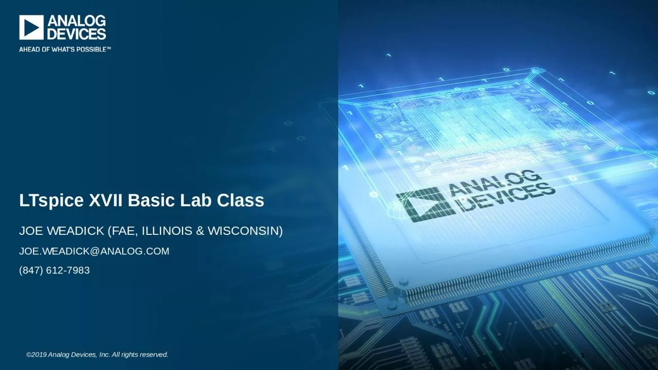
/
Joe Weadick (FAE, Illinois Joe Weadick (FAE, Illinois

Joe Weadick (FAE, Illinois - PowerPoint Presentation

TravelingSoulmate
TravelingSoulmate . @TravelingSoulmate
Follow
342 views
Uploaded On 2022-08-04

Joe Weadick (FAE, Illinois - PPT Presentation

amp Wisconsin JoeWeadickanalogcom 847 6127983 LTspice XVII Basic Lab Class 1 Why Use LTspice Stable SPICE circuit simulation with Unlimited number of nodes Schematicsymbol editor ID: 935568

ltspice click spice circuit click ltspice circuit spice simulation waveform load asc current left models schematic wire ltc3412a select

Share:

Link:

Embed:

Download Presentation from below link

Download Presentation The PPT/PDF document "Joe Weadick (FAE, Illinois" is the property of its rightful owner. Permission is granted to download and print the materials on this web site for personal, non-commercial use only, and to display it on your personal computer provided you do not modify the materials and that you retain all copyright notices contained in the materials. By downloading content from our website, you accept the terms of this agreement.


Presentation Transcript

Slide1

Joe Weadick (FAE, Illinois & Wisconsin)Joe.Weadick@analog.com(847) 612-7983

LTspice XVII Basic Lab Class

1

Slide2

Why Use LTspice?Stable SPICE circuit simulation with:

Unlimited number of nodesSchematic/symbol editor

Waveform viewer

Library of passive devices

Fast simulation of switch mode power suppliesSteady state detectionTurn on transientStep responseEfficiency / power computationsAdvanced analysis and simulation optionsNot covered in this lab class (sort of)Outperforms or as powerful as pay-for toolsIn other words LTspice is free!Automatically builds syntax for common tasks

2500+

macromodels of Legacy Linear Technology products1500+ power products300+ Legacy ADI Products (power and amps)

LTspice is also a great schematic capture / BOM tool

SPICE = Simulation Program with Integrated Circuit Emphasis

Slide3

How Do I Get LTspice and Documentation?

Go to

http://www.analog.com/LTspice

Left-Click on Download LTspice for Windows 7, 8 and 10

Follow the instructions to install

LTspice is a standalone application that runs on your computer

At this link, you will also find:LTspice Download LinksLTspice Demo CircuitsLTspice DocumentationLTspice Technical Articles & VideosSPICE Models

Slide4

How Do I Get Started using LTspice?

Slide5

How Do I Get Started Using LTspice?

Demo Circuits: Use one of the 100

s of demo circuits available at analog.com

Designed and Reviewed by Factory Apps Group

Go to http://www.analog.com/LTspice or browse through the part’s webpage for LTspice simulation informationJIG Files: Use a pre-drafted test fixture (JIG)Provides a good starting point, but is not production-readyUsed to prove out part models, and are not complete designsComponents are typically “ideal” components and will need to be modified based on your operating conditionsUse simulation circuits posted on the LTspice Yahoo! User’s GroupURL =

https://groups.yahoo.com/neo/groups/LTspice/infoAlso contains many very helpful discussion threads and tutorialsUse the schematic editor to create your own designLTspice contains models for most LTC power devices, opamps, and many moreADI opamp models are being added to the LTspice library (nearly 100 ADI models to date)LTspice can be used to simulate any analog circuit you can think of!

Slide6

Demo Circuits at analog.com

Go to

http://www.analog.com/LTspice

and scroll down to the demo circuits section:

What if I

’m browsing the part’s webpage?

Slide7

Demo Circuits at analog.com (cont.)

Go to the part’s webpage (LT8641 example):

Click on “Tools & Simulations” to find reference LTspice circuit(s)

http://www.analog.com/LT8641

Slide8

What are Demo Circuits ?

LTspice demo circuits are designed and reviewed by the LTC factory apps group

It remains the customer

s responsibility to verify proper and reliable operation in the actual application.

Printed circuit board layout may significantly affect circuit performance and reliability.What if I cannot find a LTspice demo circuit ?

Slide9

How Do I Get Started Using LTspice?

Demo Circuits: Use one of the 100

s of demo circuits available at analog.com

Designed and Reviewed by Factory Apps Group

Go to http://www.analog.com/LTspice or browse through the part’s webpage (right column)JIG Files: Use a pre-drafted test fixture (JIG)Provides a good starting point, but is not production-readyUsed to prove out part models, and are not complete designsComponents are typically “ideal” components and will need to be modified based on your operating conditionsUse simulation circuits posted on the LTspice Yahoo! User’s GroupURL = https://groups.yahoo.com/neo/groups/LTspice/info

Also contains many very helpful discussion threads and tutorialsUse the schematic editor to create your own designLTspice contains models for most LTC power devices, opamps, and many moreADI opamp models are being added to the LTspice library (nearly 100 ADI models to date)LTspice can be used to simulate any analog circuit you can think of!

Slide10

Pre-drafted Test FixtureThese simulations / designs are not production-ready, but are a great starting point!

Used to prove out part models, and are not complete designsComponents are typically

ideal

” components and will need to be modified based on your operating conditionsIt remains the customer’

s responsibility to verify proper and reliable operation in the actual application.Printed circuit board layout may significantly affect circuit performance and reliability.

Slide11

Opening a Test Fixture

1. Edit menu, select

Component”

2. Search for

macromodel

(ex. LTC3412A)

3. Click Here

Slide12

Opening a Test Fixture

Voilà !

Slide13

New Components in LTspice Library With AD, ADP, ADM, and ADuM Prefixes

Slide14

How Do I Get Started Using LTspice?

Demo Circuits: Use one of the 100

s of demo circuits available at analog.com

Designed and Reviewed by Factory Apps Group

Go to http://www.analog.com/LTspice or browse through the part’s webpage (right column)JIG Files: Use a pre-drafted test fixture (JIG)Provides a good starting point, but is not production-readyUsed to prove out part models, and are not complete designsComponents are typically “ideal” components and will need to be modified based on your operating conditionsUse simulation circuits posted on the LTspice Yahoo! User’s GroupURL = https://groups.yahoo.com/neo/groups/LTspice/info

Also contains many very helpful discussion threads and tutorialsUse the schematic editor to create your own designLTspice contains models for most LTC power devices, opamps, and many moreADI opamp models are being added to the LTspice library (nearly 100 ADI models to date)LTspice can be used to simulate any analog circuit you can think of!

Slide15

LTspice Yahoo! User’s Group

https://groups.yahoo.com/neo/groups/LTspice/info

Join the group here.

As of March 2019, there are over 69,000 members!

Several hundred message posts a month!

Slide16

How Do I Get Started Using LTspice?

Demo Circuits: Use one of the 100

s of demo circuits available at analog.com

Designed and Reviewed by Factory Apps Group

Go to http://www.analog.com/LTspice or browse through the part’s webpage (right column)JIG Files: Use a pre-drafted test fixture (JIG)Provides a good starting point, but is not production-readyUsed to prove out part models, and are not complete designsComponents are typically “ideal” components and will need to be modified based on your operating conditionsUse simulation circuits posted on the LTspice Yahoo! User’s GroupURL = https://groups.yahoo.com/neo/groups/LTspice/info

Also contains many very helpful discussion threads and tutorialsUse the schematic editor to create your own designLTspice contains models for most LTC power devices, opamps, and many moreADI part models are actively being added to the LTspice library (nearly 100 ADI models to date)LTspice can be used to simulate any analog circuit you can think of!

Slide17

Start With a New Schematic

To open up a blank schematic screen select

File

” Menu and “New Schematic”

Blank schematic

a.k.a.MasterPiece in progress

Slide18

Using the Schematic Editor in LTspice

Slide19

How to Wire up a Simple RC Circuit

The completed exercise:

Slide20

Toolbar and Keyboard Shortcuts

Place Circuit Element

[F2]

Place Diode

[D]

Draw Wire

[F3]

Place Ground

[G]

Label Node

[F4]

Place Resistor

[R]

Place Capacitor

[C]

Place Inductor

[L]

Zoom In

Pan

Zoom Out

Autoscale

Paste b/t Schematics

[Ctrl+V]

Duplicate

[Ctrl+C]

Find

[Ctrl+F]

Delete

[Del]

Place SPICE directive

[S]

Place Comment/text

[T]

Mirror

[Ctrl+E]

Rotate

[Ctrl+R]

Redo

[Shift+F9]

Undo

[F9]

Drag

[F8]

Move

[F7]

Slide21

How to Wire up a Simple RC Circuit

Step 1: Open up a blank schematic screen

Select

File” Menu and “

New Schematic”

Slide22

How to Wire up a Simple RC Circuit

Step 2: Add the passives and grounds

Using the toolbar, select Resistor, Capacitor and Ground. Place these symbols on the schematic as shown below. Use

Ctrl+R

to rotate before placement.

Select and place res, cap & GND, or use keyboard keys R, C, and G

Tip:

Ctrl+R

to rotate before placement

Slide23

How to Wire up a Simple RC Circuit

Step 3: Add the voltage source

Select

Edit

” Menu and “Component”. From the component window, start typing “voltage” in the dialog box, and click “OK”

1. Edit menu, select “

Component”

2. Type

Voltage

3. Click

OK

Slide24

How to Wire up a Simple RC Circuit (cont.)

Step 4: Wire up the circuitUsing the toolbar, select Wire, or, press F3

1. Select

Wire

” button

Slide25

How to Wire up a Simple RC Circuit (cont.)

Step 4: Wire up the circuit (cont.)

Left-Click ground

“Pull” wire up through the source

Left-Click here to anchor

“Pull” wire through the resistor

Left-Click here to anchor

“Pull” wire down through the capacitor

Left-Click here to anchor & finish

Hint: Press the ESC key at any time to clean up the schematic

Slide26

How to Wire up a Simple RC Circuit (cont.)

Step 5: Add net labels

Using the toolbar, select Label Net (or press F4). Label the input/output nodes as shown below

1. Select

Label Net

2. Enter net name

3. Place on wire

Slide27

How to Wire up a Simple RC Circuit (cont.)

Step 6a: Component values

Right-Click on each component symbol to change its value as shown below

Right-click on symbol

Or Right-click on value

Slide28

Using Labels to Specify Units for Component Attributes

K = k = kilo = 103MEG = meg = 10

6

G = g = giga = 10

9T = t = tera = 1012M = m = milli = 10-3U = u = micro = 10-6

N = n = nano = 10-9P = p = pico = 10-12F = f = femto = 10-15

HintsUse MEG (or meg) to specify 106, not MEnter 1 for 1 Farad, not 1F

Slide29

Editing Components

You can also edit the visible attribute and label by pointing at the text with the mouse and then right-clicking

Mouse cursor will turn into a text caret

Right-Click

on the component to edit attributes

Slide30

Component Database

Resistors, capacitors, inductors, diodes, Bipolar transistors, MOSFET transistors, JFET transistors, Independent voltage and current sources

You can access a database of known devices

Slide31

How to Wire up a Simple RC Circuit (cont.)

Step 6b: Source parameters

Right-Click on the voltage source and enter the parameters shown below under the

Advanced

” tab.

Right-click source

Click

Advanced

Slide32

How to Wire up a Simple RC Circuit (cont.)Step 6b: Source parameters

Select the PULSE button and enter the parameters shown below:

Slide33

Running and Probing a Circuit in LTspice

Slide34

Summary of Hotlinks Used in This PresentationThe following hotlinks are used in this presentation for opening up LTspice simulation files

Note:

Presentation Mode must be used for the hotlinks to work

Class exercise

Solution to exercise

Circuits to explore at your leisure

Slide35

Running the RC Circuit Simulation – Transient Analysis

With the RC circuit in the active window, click on the RUN button on the toolbar

The Edit Simulation Command window will appear. Set the Stop Time to 60m and click OK.

Using the mouse, click on the IN node and OUT node to display the input and output voltage waveforms.

Run

Click here for output waveform

RCFilterTimeDomain.asc

Slide36

Running the RC Circuit Simulation – Transient Analysis

To add a measurement cursor to the waveform window,

left+click

the mouse on the waveform name.

Click to display measurement cursor. Click and drag cursor position.

To add a second measurement cursor (paired cursors), just

left+click

on the waveform name again.

RCFilterTimeDomain.asc

Slide37

Running the RC Circuit Simulation – Transient Analysis

To display the current in the resistor, just

left+click

on the resistor.

Click here for resistor current waveform

RCFilterTimeDomain.asc

Slide38

Running the RC Circuit Simulation – Transient Analysis

Split the plot pane by selecting “Add Plot Pane” under the Plot Settings pull-down menu.Drag and drop the I(R1) waveform title into the new plot pane

RCFilterTimeDomain.asc

Slide39

Summary of the Waveform Viewer

LTspice integrated waveform viewer:Plot the voltage on any wire by a simple point and click

Plot the current through any component by clicking

on the body of the component

When using the current probe, the convention ofpositive current is from netlist pin #1 to pin #2.Add a waveform measurement cursor by left+clicking on the waveform name. Add a second measurement cursor by left+clicking on the waveform name again.

Voltage probe cursor

Current probe cursor

Slide40

AC Analysis

Slide41

AC Analysis Overview

Performs small signal AC analysis linearized about the DC operating point

Useful for analysis of filters, networks, stability analysis, and noise considerations

Slide42

Simulating AC Analysis – RC Filter

Single pole filter using RC network

Syntax: .ac <

oct

,

dec, lin> <

Nsteps> <StartFreq> <EndFreq>Example: RC network and .ac dec 100 .01 1MEG

-3dB point: 1/(2*pi*R*C) = 159Hz

Right-click on .

tran

command and select

AC Analysis

AC amplitude of 1 sets magnitude to 0dB

Slide43

Simulating AC Analysis – RC Filter

Right-click on the .

tran

command

Select AC Analysis tab

Enter the following parameters:

Slide44

Simulating AC Analysis – RC Result

Click here for Bode plot

Slide45

Simulating AC Analysis – Active Filter

Single pole active filter using an

opamp

(AD8672)

Click here for Bode plot

ActiveFilterACSweep.asc

Slide46

Defining a Component Value as a Variable(a taste of intermediate & advanced topics)

Slide47

Defining a Component Value as a Variable (Using Parameters)

The .

param

SPICE directive allows the creation of user-defined variables.

To define a component value as a variable, replace the component value with a variable name enclosed in curly braces. Example: {X}

Right+click to change the component value to {X}

Add the .

param

SPICE directive

(press S on the keyboard)

RCFilterACAnalysis_Param.asc

Slide48

Defining a Component Value as a Variable (Using Parameters)

The simulation results are the same as when the component value was defined as 10K.

Click here for Bode plot

RCFilterACAnalysis_Param.asc

Slide49

Defining a Component Value as a Variable (Stepping Parameters)

The .STEP command can be used to vary a component variable over a range of values to plot a family of curves.

This is very powerful and can be used for sensitivity and Monte Carlo Analysis.

Right+click

to change SPICE directive to the .step command

RCFilterACAnalysis_Step Command.asc

Slide50

Defining a Component Value as a Variable (Stepping Parameters)

For this AC analysis example, the simulation result includes three Bode plots, one each for R = 10K, 20K, and 30K

Click here for Bode plot

RCFilterACAnalysis_StepCommand.asc

Slide51

Running a DC/DC Converter Simulationand Analyzing Circuit Performance

Slide52

Running a DC/DC Converter Simulation

Access the LTC3412A circuitClick File ---> Open, and navigate to the LTspice Lab folder on your desktop. Look for the file titled

LTC3412A_DC_Load.asc

”Or click “c” symbol on the right

LTC3412A_DC_Load.asc

Slide53

Viewing Voltage Waveforms

Plot the voltage on any wire by

Left-Clicking

it

Tip: All Demo Circuits have INs and OUTs clearly labeled to help you quickly select them

Click here for output waveform

LTC3412A_DC_Load.asc

Slide54

Viewing Current Waveforms

Plot the current through any component by

Left-Clicking

on the body of the component

Current flowing into a node is defined as being positive

Click here for inductor current waveform

LTC3412A_DC_Load.asc

Slide55

Zooming In and Out on a Waveform

In the waveform window, use the mouse to zoom in and out. Click and drag a box about the region you wish to see drawn larger

Using the toolbar, click on

Zoom full extents”

, to zoom back out

LTC3412A_DC_Load.asc

Zoom Full Extents

Slide56

Measuring V, I and Time in the Waveform

(Measurement Using Cursors)

Right-Click

on the waveform name in the waveform window

For

“Attached Cursor”, select “1st & 2nd” Position cursors to make desired measurements

1.

2.

3.

Result

LTC3412A_DC_Load.asc

Slide57

Measuring V, I and Time in the Waveform

(Measurement Using Zoom Window)

Drag a box about the region you wish to measure

Left-Click

, drag, and hold

View the lower left corner of the window for the status bar. The dx and dy

measurement data is displayed here.Use Undo from the File menu or press “F9”

LTC3412A_DC_Load.asc

Slide58

Viewing Differential Voltage Waveforms

Left-Click

on one node and drag the mouse to another node

Red voltage probe at the first node

Black probe on the second

LTC3412A_DC_Load.asc

Slide59

Viewing Differential Voltage Waveforms

To create a measurement reference node,

Right-Click

on the desired node and select “Mark Reference”

A black voltage probe is anchored to the selected node

All measurements in the circuit are now referenced to the node with the black probe Hit the ESC key to remove the reference markLTC3412A_DC_Load.asc

Slide60

Viewing Wire Current Waveforms

Plot the current through any wire by

Alt+Left-Clicking

on the wire

An ammeter will appear to indicate that the wire current will be displayed

LTC3412A_DC_Load.asc

Slide61

Average & RMS Calculations

Average & RMS Current, Voltage, or Power Dissipation

Calculated only for the visible area of the plot window

Click on inductor L1 to display the inductor current waveform

Ctrl+Left-Click the I(L1) trace label in the waveform view

Example:Measure average and RMS current for inductor in LTC3412A circuit. Zoom in as shown for this waveform.

LTC3412A_DC_Load.asc

Slide62

Instantaneous & Average Power Dissipation

Instantaneous Power Dissipation

Alt+Left-Click

on the symbol of the LTC3412A

Waveform is displayed in units of Watts

Average Power Dissipation Click, hold, and drag in the waveform window to display waveform at steady stateCtrl+Left-Click on the Power Dissipation Trace Label in the waveform viewWaveform summary window will appear which shows power dissipation in the IC

Example:

Measure the power dissipation in the LTC3412A IC

LTC3412A_DC_Load.asc

Slide63

Deleting Waveforms

Method #1: Right-Click on a trace label to be deleted

Select “Delete this Trace”

Deletes only the selected trace

LTC3412A_DC_Load.asc

Slide64

Deleting Waveforms

Method #2: If the plot window is active hotkey F5 is equivalent

Cursor turns into scissors

Left-Click

on one or more trace labels to delete. ESC to quit

LTC3412A_DC_Load.asc

Slide65

Deleting Waveforms

Method #3: Plot the same waveform twice in succession

Deletes all but that waveform

Click, click

LTC3412A_DC_Load.asc

Slide66

Net Labeling

Slide67

Advantages of Labeling

Replaces the default SPICE node names with node names and waveform titles that are easy to understand and remember

Allows LTspice circuit nodes to match those on your production schematic, i.e.

TP15

Without

With

LTC3412A_DC_Load.asc

Slide68

Labeling - Trick

Highlight net from waveform viewer

Alt-Left-Click on the label in the waveform viewer (i.e. V(n006)) and it will now highlight that particular net on the schematic. You can also use the search function ( )

Net Highlighted

Alt-Left-Click

LTC3412A_DC_Load.asc

Slide69

Generating a BOM and Efficiency Report

Slide70

BOM

Under View select Bill of Material

Displayed on Diagram

Paste to Clipboard

LTC3412A_DC_Load.asc

Slide71

Steps to Computing Efficiency

Note: Efficiency will only be calculated in the steady state condition

1.)

Right-Click

the .tran

statement on the schematic to bring up the Edit Simulation Command dialog box2.) Check the box “Stop simulating if steady state is detected” …

1. Simulate menu, select “Edit simulation Cmd”

2. Check Box

LTC3412A_DC_Load.asc

Slide72

Steps to Computing Efficiency

3.) Load must be a current source or a resistor labeled Rload**

4.) Run the simulation …

The Good

The Bad

This will be treated just like any other resistor – efficiency will read

ZERO

Slide73

Steps to Computing Efficiency

5.) Upon completion select the View dropdown menu, Efficiency Report, then Show on Schematic

6.) Efficiency report will be pasted under the schematic

LTC3412A_DC_Load.asc

Slide74

SMPS Efficiency Tips

LTspice will not always be able to determine steady state, but this is rare!

Workaround:

Alt+Left-Click

on individual component and integrate waveformProbe the various nodes and verify the circuit is stabilizedIf not, edit the .tran statement and increase the Stop Time parameter. Re-run simulationFor multiple output and/or multiple input supplies, efficiency must be determined partially by hand from the efficiency report

Alternatively use behavioral modelsRight-Click any component will report power dissipation if steady state has been detected or Mark Start/End has been usedIf circuit has stabilized for a long time and LTspice still hasn’t detected the steady-stateUse Mark Start/End (Simulate pull-down menu ---> Efficiency Calculation ---> Select Mark Start/End)Only steady-state data is displayed before Mark End

Slide75

Simulating a Transient Response

Slide76

Current Load and Pulse Function

You can simulate a load with a Resistor or Current (active) load

In particular, the Pulse function with a current load is helpful for transient response analysis

Steps a current load from one load value to another load value

LTC3412APulseLoadSolution.asc

Slide77

Edit the Current Load to a Pulse FunctionEdit the .

tran directive in the LTC3412A simulation to disable steady state detectionRight-Click

on the current load

Select

“Pulse”Modify the attributes (see below). Click “OK”

*

Forces current to be zero when voltage is zero

Slide78

Run the Simulation for Transient Response

Run the simulation

Click on the OUT node to display

Vout

Click on the output current load to display

IoutNotice the presence of the pulse loadUse the application of the pulse load / transient response to verify stability and modify the compensation components as necessary.

LTC3412APulseLoadSolution.asc

Slide79

Importing Third Party SPICE Models

Slide80

Importing Third Party SPICE Models

Steps for importing a third-party SPICE model:

1.) Download the

SPICE

model file from the manufacturer’s website

2.) Place the

SPICE model file in the same directory as the LTspice simulation file (simplest). It can be placed in another folder on your computer or even on a network drive.3.) Open up the SPICE model file and note the device name4.) Add the following SPICE directive to the LTspice simulation schematic (Edit pull-down menu ---> SPICE Directive): .include spice_model_file_name.abc

5.) Modify the device name on the LTspice schematic to match the device name listed in the SPICE model file (Right+Click on the device name on the simulation schematic and modify accordingly).

Slide81

Importing Third Party SPICE Models

The following items are

CRITICAL!

1.) The file name in the .include statement must match the

SPICE

model file name identically! The file name syntax is can be anything, just make sure that all of the characters match.

2.) The device name on the LTspice simulation schematic must match the device name in the SPICE model file identically! The device name syntax can be anything, just make sure that all of the characters match.

Slide82

Importing Third Party SPICE Models

SPICE Model Example #1:

File name = 1N5244B.mod

Model name = 1N5244B1

SPICE Model Example #2:

File name = Joe.txt

Model name = Everest

Summary:

The file and device names are irrelevant. Just make sure that the LTspice simulation device name and .include file name match those of the SPICE model file.

Slide83

Importing Third Party SPICE Models

Hands-on Exercise:

1.) Navigate to the LTspice Training Files folder

2.) Open up the simulation file titled “Zener Import

Example.asc

3.) Open up the SPICE model file titled “1N5244B.mod” and note the device name.4.) Modify the simulation file so that it uses the 1N5244B third-party SPICE model based on the instructions provide on the previous slides5.) Run the simulation and probe the IN and OUT nodes

Slide84

Importing Third Party SPICE Models

Solution:

1.) Zener name changed to 1N5244B1 to match device name in the SPICE model file.

Right+Click

on the diode name text to change.

2.) .include SPICE directive added to link to the SPICE model file. Use the Edit pulldown menu -

--> SPICE Directive to add this SPICE directive to your simulation.3.) Result after clicking on the Running Person symbol on the toolbar and probing the IN and OUT nodes.

Slide85

Steps:

1.) Download the AD8237 SPICE model from the ADI website

2.) Open up the AD8237 SPICE model using LTspice

3.) Use LTspice to autogenerate the schematic symbol (right-click on the .SUBCKT statement)

4.) Wire up the circuit

Importing Third Party SPICE Models: Practical Example Using AD8237

Slide86

Autogenerated Schematic Symbol:

Importing Third Party SPICE Models: Practical Example Using AD8237

Slide87

Final Implementation:

Importing Third Party SPICE Models: Practical Example Using AD8237

Slide88

More Information and Support

Slide89

ADI / LTC Design Tools That Autogenerate LTspice Simulation Circuits

1.)

LTpowerCAD

http://www.analog.com/LTpowerCAD

2.) Analog Filter Wizard

http://www.analog.com/designtools/en/filterwizard/

3.) Photodiode Circuit Design Wizard

http://www.analog.com/designtools/en/photodiode/

Slide90

Reminder to Periodically Sync Release It is important to sync your release of LTspice periodically to get the latest updates

Software updates and bug fixesModels

Sample circuits and examples

Tools pull-down menu ----> Sync Release

**May need to run LTspice as administrator or run “Elevated”

Slide91

Reminder to Periodically Sync Release (Windows) Vista, Win7, and Win8 users (any UAC-enabled OS)

You must “Run as administrator

LTspice.exe or its shortcut even if you are logged in as an administrator

Slide92

Reminder to Periodically Sync Release (Mac)

1. Open

Control Panel

2. Under

Operation

3. “

Sync Release

” for Mac

Slide93

Built-in Help System

Slide94

Appendices

Slide95

Other ResourcesLTspice forum: Use simulation circuits posted on

LTspice Yahoo! User’s Group

Go to

https://groups.yahoo.com/neo/groups/LTspice/info

Also contains many very helpful discussion threadsEducational Files: Check out LTspice capabilities using the education examples Available on C:\Program Files\LTC\LTspiceXVII\examples\EducationalLTspice videos: Video tutorials by Linear’s technical staff

LTspice Videos at www.analog.comLTspice Videos on YouTube!https://www.youtube.com/results?search_query=ltspiceLTwiki: Undocumented features …http://ltwiki.org/Wurth LTspice Book – available at Amazon, or, contact your local Wurth field sales engineer

Slide96

Other Resources – Educational Files

Design examples demonstrating LTspice capabilities

Slide97

Other Resources – LTwiki

http://ltwiki.org/

Slide98

Other Resources

– LTspice

B

ook

Other Resources – LTspice Book

Slide99

Appendix - Steps to Calculate Power Supply EfficiencyEfficiency will only be calculated in the steady state condition

Right-Click the .tran statement on the schematic to bring up the Edit Simulation Command dialog box

Check the box

Stop simulating if steady state is detected”Load must be a current source or resistor labeled RloadRun the simulationUpon completion select the View dropdown menu, then Efficiency Report, then Show on SchematicEfficiency report will be pasted under the schematic

Slide100

Appendix – Summary of Special Mouse and Keyboard CommandsSchematic-Based Special Commands

Alt-Left-Click on a wireThis will display the waveform for the current flowing in the wire

Alt-Left-Click

on a component

This will display the instantaneous power dissipation in the componentCtrl-Right-Click on a componentAllows you to edit embedded component attributesWaveform-Based Special CommandsCtrl-Left-Click on a waveform titleDisplays the average and RMS values for the waveformLeft-Click on node and drag to another node

Displays differential voltageAlt-Left-Click on the label in the waveform viewer (i.e. V(n006))Particular net on the schematic is highlighted

Slide101

Appendix – Summary of Additional FeaturesPause a simulation

“Simulate”

pull down menu ---> Pause

There is no toolbar button for this function

Zoom in/out using the schematic editor:Just use the wheel on your mousePan around a schematicLeft-Click-Hold the mouse, then dragTilt wheel to move right and leftMove a window to another monitor (new to LTspice XVII)Right-Click on window contents, then from the context menu check box “Float Window”Left-Click-Hold the window title bar to drag to another monitor

Slide102

Thank you for attending, and happy simulating!

Homework:

Once you return to the office, go back over the training materials within a week!