/
CW Operation  of  XFEL Modules Outline Limitations of the XFEL cryo module for high duty CW Operation  of  XFEL Modules Outline Limitations of the XFEL cryo module for high duty

CW Operation of XFEL Modules Outline Limitations of the XFEL cryo module for high duty - PowerPoint Presentation

alida-meadow
alida-meadow . @alida-meadow
Follow
343 views
Uploaded On 2019-11-02

CW Operation of XFEL Modules Outline Limitations of the XFEL cryo module for high duty - PPT Presentation

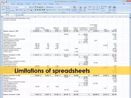
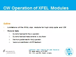
CW Operation of XFEL Modules Outline Limitations of the XFEL cryo module for high duty cycle and CW Module tests Dynamic heat load for the cw operation Dynamic heat load measurements vs duty factor ID: 762136

heat load dynamic operation load heat operation dynamic cavities xfel acc cryomodule linac hom test gradient long measured estimated

Share:

Link:

Embed:

Download Presentation from below link

Download Presentation The PPT/PDF document "CW Operation of XFEL Modules Outline L..." is the property of its rightful owner. Permission is granted to download and print the materials on this web site for personal, non-commercial use only, and to display it on your personal computer provided you do not modify the materials and that you retain all copyright notices contained in the materials. By downloading content from our website, you accept the terms of this agreement.


Presentation Transcript

CW Operation of XFEL Modules OutlineLimitations of the XFEL cryo module for high duty cycle and CWModule tests Dynamic heat load for the cw operationDynamic heat load measurements vs. duty factor Maximum gradient test for the lp operationVector sum stabilization with RF-feedback Wolf-Dietrich Möller, slides are from Jacek Sekutowicz TTC topical meeting on CW SRF 12th – 14th June 2013, Cornell University

Limitations for the XFEL Module and Linac 1The XFEL main linac consists out of 7 cryo strings, every string includes 12 cryo modules, every cryo module contains 8 cavities. 2.2 K forward 5 K forward 40 K forward 2-phase tube: 240 W ( 20W/cryomodule) is the estimated limit for one cryo string. 2 K, Gas Return Tube 80 K, Return 8 K, Return 1 st limit: H eat load at 2K for each cryomodule must not exceed 20 W.

Limitations for the XFEL Module and Linac 2Each cryomodule houses 8 cavities (in total there will be 808 cavities in the linac) Cavity was designed for ca. 1% DF. End groups (FPC and HOM couplers) are cooled by means of heat conduction. HOM coupler HOM coupler FPC D issipation on the HOM coupler antennas is the main sources of the heat for the end groups.

Limitations for the XFEL Module and Linac 32nd limit: Heating of the HOM couplers must not lead to quenching of the end-cells. Experience with vertical tests (cavities immersed in the superfluid bath): Without HOM antennae: E acc up to 45 MV/m in the cw mode With HOM antennae: E acc up to 40 MV/m in the lp mode DF = 10 %

Limitations for the XFEL Module and Linac 4 Other, “practical” limits:3 rd limit: The main XFEL linac will not be rebuilt for the new operation modes Minor modifications in the cryomodule (cavities) have to be done now, prior to the series production. Linac can be extended with 12 cryomodules from the injector section. 4 th limit: An upgrade of the cryogenic plant should be “doable” 5 th limit: N ew RF-sources will be added to the klystrons we plan to use for the nominal operation. The new sources should fit in the tunnel. We plan to have a single RF-source/CM.

CW and Long Pulse Operation Modes Proposed new operation modes for the XFEL: Continuous wave operation for E acc ≤ 7 MV/m Long pulse operation at E acc > 7 MV/m with DF ~ (7/E acc )2 Example of long pulse operation at E acc = 14 MV/m 750 ms f rep = 1Hz ~100 fs 1s 250 ms 4 µs for 1 nc Bunch quality as high as for the nominal short pulse operation.

Dynamic heat load for the cw operation, 1 Goal: Measurement of dynamic 2K heat load for the cw operation.Conditions: 7 cavities in operation (C#7 had detuned HOM coupler. It was operable <4MV/m). End-groups were thermally connected to the 2K tube. < Q load > = 1.5E7 , 3 dB resonance width 87 Hz. Eacc = 5.6 MV/m. Pout IOT ~ 4.4 kW , RF-power/coupler ~ 550 W. Feedbacks: RF off a nd piezo on.Estimated dynamic heat load and measured static load: For assumed Qo = 1.7E10 at this gradient dynamic heat load should be 13.7 W. Cryomodule static loss 4.5 W. For experiments we equipped CryoModule Test Bed with cw operating RF-source (IOT).Example #1 of the cw run

Dynamic heat load for the cw operation, 2 Dynamic HL = 16 W < Eacc > = 5.6 MV/m Reference 5 W Eacc =0 MV/m 2K dynamic loss at Eacc= 5.6 MV/m Measured dynamic heat load for 7 cavities was 16 W.

Dynamic heat load for the cw operation, 3 Conclusion: The difference of 2.3 W between measured and estimated HL can be attributed to warming of 14 end-groups, which is 0.16 W/(end-group) . Projecting this result on 8 cavities operating at 1.8 K , one might expect cw operation at E acc close to 7 MV/m if Qo at that gradient is 3.4 E10.

Dynamic heat load measurements vs. duty factor, 1 Goal: Measurement of the dynamic 2K heat load vs. DF for lp operation.Conditions: <E acc > = 8.1 MV/m, Rep . rate 0.7 Hz . 6 cavities in operation, (C#7 detuned HOM coup., C#8 quenched at 9.3 MV/m at larger DF). Feedbacks: RF off, piezo feedback and bias on.Test Result: for the DF range from 15% to 47%. Reference 1W; 0 MV/m DF =47% DF =39% DF =31% DF =25% DF =21% DF =15% Example #2 of the long pulse run

Dynamic heat load measurements vs. duty factor, 2 Test Result, cont.: Diagram showing measured and estimated Heat Load (HL) at 2K.

Dynamic heat load measurements vs. duty factor, 3 Conclusion: The cryomodule (6 cavities) could be operated very stable at 8.1 MV/m at up to 650 ms long flat top + 33 ms filling. No anomalous behavior was observed up to this flat top and 47% DF. The difference between measured and estimated heat load for long pulses can be attributed to higher operating temperature of 12 end-groups. These additional heat is ~280 mW /end-group at 650 ms long flat top. Projecting this result for 8 cavities operating at 1.8 K , DF = 14%, one might expect to reach 20 MV/m for the 20 W/cryomodule with repetition rate of 1 Hz.

Maximum gradient test for the lp operation, 1 Goal: Measurement of the dynamic 2K heat load at higher gradients.Conditions: Maximum IOT Pout was ca. 18 kW , due to strong reflection in the input circuit of IOT and reflection in the RF-power distribution system. E acc = 10.5 MV/m (6 good cavities) + C# 8 was operated at 8 MV/m. DF= 17 %, repetition rate 0.7 Hz and flat top ca. 200 ms. Feedbacks: RF off, piezo on.Estimated dynamic heat load and measured static load: For assumed Qo = 1.7E10 at this gradient, the dynamic heat load is 5.3 W. Static heat load of the tested cryomodule was 4.5 W. Example #3 of the lp run

Maximum gradient test for the lp operation, 2 Test Result: System was operating stable for ca. 2h, no anomalous behavior was observed. Reference 1 W; 0 MV/m Dynamic HL = 6.3 W < Eacc > = 10.5 MV/m Conclusion: As before, 1 W difference between the dynamic measured and estimated heat load is due to losses in the end-groups, ca. 0.08 W/(end-group ). Again, projecting this result for 8 cavities operating at 1.8 K, one should be able to reach 21.5 MV/m at DF=17%, flat-top ~140 ms for the budget of 20 W/CM.

Vector sum stabilization with RF-feedback RF-feedback offStandard deviations for: Amplitude = 1.5E-3Phase = 0.5° Goal: Stability of the vector sum for the cw operation with the new µTCA LLRF. Conditions : E acc = 3.5 MV/m , mode cw, piezo feedback off, bias on.Test Result: Conclusion: New µTCA RF-feedback improves amplitude and phase stability by factor of 24 and 51 respectively, and fulfills spec for the XFEL linac. RF-feedback onStandard deviations for: Amplitude = 6.2 E-5Phase = 0.0098° 1s 1s Vector sumVector sumphase phase

conclusion The experiments showed feasibility of more flexible operation for the XFEL linac.Following must be demonstrated in near future with coming XFEL-like cryomodules:Benefit to operate at 1.8 K (can we get to higher gradients for 20W/cryomodule ?).Higher gradients than 10.5 MV/m in lp operation (maximum Eacc vs. DF). S uperconducting RF gun needs more R&D Test stand for SRF guns should be ready in 2014. Other superconductors or photo-emitters should be studied. R&D programs for 1.3 GHz and 3.9 GHz cavities should give an answer by the end of 2014 how high in gradient we can go for the cw mode.

Acknowledgements Thank you Jacek, that you allowed me to present your experiment. Jacek: I want to express my gratitude to all Colleagues contributing to the experiments: DESY: V. Ayvazyan, J. Branlard, W. Cichalewski, M. Ebert, N. Engling, J. Eschke, T. Feldmann, A. Goessel, W. Jalmuzna, D. Kostin, M. Kudla, D. Makowski, F. Mittag, W. Merz, C. Müller, R. Onken, A. Piotrowski, K. Przygoda, I. Sandvoss, A. Sulimov.