/
Optimization of outrigger locations in steel tall buildings Optimization of outrigger locations in steel tall buildings

Optimization of outrigger locations in steel tall buildings - PDF document

alida-meadow
alida-meadow . @alida-meadow
Follow
455 views
Uploaded On 2015-09-16

Optimization of outrigger locations in steel tall buildings - PPT Presentation

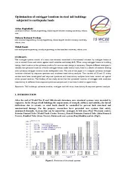
sas subjected to earthquake loads Abbas Haghollahi Assistant Professor Faculty engineering Shahid Rajaee Teacher Training University Tehran Iran Mohsen Besharat Ferdous Msc Structur e Engineer ID: 130813

sas subjected earthquake loads Abbas Haghollahi Assistant

Share:

Link:

Embed:

Download Presentation from below link

Download Pdf The PPT/PDF document "Optimization of outrigger locations in s..." is the property of its rightful owner. Permission is granted to download and print the materials on this web site for personal, non-commercial use only, and to display it on your personal computer provided you do not modify the materials and that you retain all copyright notices contained in the materials. By downloading content from our website, you accept the terms of this agreement.


Presentation Transcript

Optimization of outrigger locations in steel tall buildings sas subjected to earthquake loads Abbas Haghollahi Assistant Professor , Faculty engineering, Shahid Rajaee Teacher Training University , Tehran, Iran Mohsen Besharat Ferdous Msc Structur e Engineering, Faculty engineering, Shahid Rajaee Teacher Training University , Tehran, Iran Mehdi Kasiri Msc Earthquake Engineering, Faculty engineering, Tarbiat Moallem University, Tehran, Iran SUMMARY : The outrigger system consist of a main core element connected to the external columns by outrigger beams at one or several floors and resist s against core’s rotation and storey drift. When using outrigger beams in building design, their location in the optimum position for an economic design is necessary . Despite different strategies to identify the optimum locations of these outrigger beams under lateral loads, there is a dearth of research dealing with optimum outrigger location under earthquake loads. The aim of this paper is to compare optimum out rigger locations obtained by response spectrum and nonlinear time - history analysis. Two models of 20 and 25 storey models have been investigated and response spectrum and time - histo ry analyses have been carried out against seven ground motions . The finding of this s tudy shows that the optimized location of outrigger with nonlinear time - history is differen t from response spectrum analyse s and it has been located in upper levels. Keywords: T all building s, optimum location, outrigger and belt truss, t ime - history & respo nse spectral analysis 1. INTRODUCTION After the end of World War II and 30th decade downturn, new structural systems were invented by engineers. In the design of tall buildings the requirements of strength, stiffness and stability, the lateral deflectio ns due to seismic or wind loads should be controlled to prevent both structural and nonstructural damage. For this purpose, researchers have presented new systems that satisfy mentioned demands. Systems that can be named for: o utrigger & belt truss ( First W iscinsi n center), Exterior Framed Tube (World Trade Center Towers), Braced Perimeter Frame d Tube (John Hancock Tower), Bundled Tube (Sears Tower), Buttressed core system (Burj Khalifa) and etc (Fig1). Figure 1. Evolution of structural systems 2 . OUTRIGG ER AND BELT TRUSS To brace medium high - rise structures, general method is bracing around the core and stair wells. In conditions with restriction using this method (buildings higher than 150 meter), lateral bracing system is employed as an effectiv e solution. This system consist s of joined shear walls with outriggers that are able to restrain inter - storey drift under wind and earthquake loads and also decrease moment of core element and its dimension. Outrigger beams are connec ted directly to shear walls or braced frames at the core element and external columns which are tied by peripheral truss in that level (Fig 2). Figure 2. Structural schematic of tall building with outrigger and belt truss (Taranath, 1988) When the lateral load acts on the structure, the bending of the core ro tates the stiff outrigger arms, which is connected to the core and induces tension and compression in the columns and forced double curvature increase its flexural stiffness (Fig 3). It is understood that performance of such systems depends mainly on adequ ate stiffness and strength of the outrigger beams . Figure 3. Performance of outrigger system against lateral load (Hoenderkamp, 2003) 2.1. History of research Studies on the effect of intermediate stiffening beam at an arbitrary level along the hei ght of the structure and were carried out by Chan and Kuang (1989) initially. They revealed that the behaviour of the structure could be significantly influenced by the specific position of this stiffening beam. Afterwards, researchers examined new approac hes to identify the helpful effect of an outrigger and multi outriggers on the structural behaviour and their best location o f the structure [Herath et al (2009) ]. The development of simplified analytical methods for outrigger braced structure began in the mid seventies. Taranath (1974) queried the optimum location of a belt truss that reduced the sway of lateral Braced Core Outrigger arms Exterior Colu mns Belt trusses loads and introduced a simple method of analysis. Afterward, McNabb et al (1975) expanded their studies with two outriggers and investigated main factor in drift reduction. McNabb et al (1975) confirmed result of Taranath’s research about optimum outrigger location (0.445 of the structure’s height from the top of it) and explained that the optimum locations for two outriggers to be 0.312 and 0.685 o f the height from the top of the building. Boggs et al (1983) investigated influence of member’s section variation along the height of the structure and affirmed it lead to moving the position of the outriggers upward. Smith at el (1991) offered simple ap proximate guidelines for the location of the outriggers to preliminary analysis. In the most of the above research , axial and flexural rigidity of the perimeter columns and core were assumed to be consistent throughout the height of the building and also l a teral loading to be uniform [Herath et al (2009) ] . But in practice, these characteristics would change hence Rutenberg et al (1987) studied the effect of these characteristics on the behaviour of the outrigger braced structure. Further Su et al (2005) inv estigated the complete load transfer mechanism between the outrigger brace and the core using strut - and - tie method. Hoenderkamp et al (2008) presented a simple method of analysis for preliminary design of outrigger braced high - rise shear walls subjected to horizontal loading. They estimated the outrigger optimum location by introducing a dimensionless parameter (  ) which related to bending and racking shear stiffness of the braced frame and outriggers in addition to a stiffness parameter representing the a xial lengthening and shortening of the exterior columns. These studies shoed importance of the outrigger’s position in the behaviour and lateral deflection of the structure. Most of the above research es have carried out by simpler analysis such as respons e spectrum analysis, so in this paper have been used complicated and accurate time - history analysis to compare the optimum outrigger location in former studies. 3 . STRUCTURAL MODE L 3 .1. Introduction of models T his study has utilized 3D models with 2 0 and 25 storey high rise steel frame braced by outrigger and belt truss system. Space between frames at direction X is 5 m and at direction Y is 5 .5 m, general prototype geometry and plan are shown in Fig 4 . The braced system of the models is with double diagonals in an “X” configuration. The models have desig ned based on AISC - ASD (89) and for definition of the hinges of the models , FEMA 356 has been used . The height of all stories is 3.2 (m) and type of soil is B by USGS description (360V s 750 m/s). ( a) ( b) ( c) Figure 4. Geom etric specifications: a) Floor p lan (b) 20 storey model (c) 25 storey model 3 . 2 . Introduction of software SAP 2000 due to its high capability in definition of hinges according to rehabilitation codes such as FEMA 356 and ability of two methods modal and direct integration in time - history analysis has utilized in this study. Before applying earthquake excitation, records should be corrected. In this procedure, the early wrong direction that has occurred due to double integration of incorrect acceleration in time - history of the displacement has been removed. For this purpose, a polyn omial function has been fitted to the acceleration curve, then by subtraction acceleration values of this function , corrected acceleration values has been obtained (Seismosignal Software, Version 4.3.0). In addition, filtering operation on the records to remove unwanted frequencies has been performed (Seismosignal Software, Version 4.3.0). 3 . 3 . Ground motions records It has been observed that behaviour of structures vary greatly from record to record. For this purpose, those records which have include s ame site condition such as type of soil and shear wave velocity have been selected. In this study the models has been used under seven earthquakes which have been listed in Table 1. In order to three dimensional time - history analysis, two perpendicular directions of records have been considered and because of negligible effect of vertical component, it has been ignored in analyses . Table 1. Some Details of Ground Motion Records Record PGA (g) Distance from the fault (km) Date Station Northridge 0 .568 22.6 1994/1/17 Old Ridge Rout Loma Perieta 0.244 21.4 1989/10/18 Anderson Dam Tabas 0.406 17 1978/9/16 Dayhook Cape Mendocino 0.549 18.5 1992/4/25 Rio Dell Overpass Victoria Mexico 0.621 34.8 1980/6/9 Cerro Prieto San Fernando 0.366 20.3 1971/2/9 Lake Hughes Chi Chi 0.512 24 1999/9/20 TCU045 In attention to Tall Building Initiative (TBI), there are two principal procedures for ground motion modification: Direct scaling and spectral matching. The direct scaling procedure consists of determining a con stant scale factor by which the amplitude of an accelerogram is increased or decreased. T his paper has used the direct scaling procedure and all PGA of the accelerograms has been scaled to 0.35(g) because of site conditions. In addition for the sak e of performing response spectrum analysis, spectra of the ground motions and average spectrum which has been utilized in analysis have been shown in Fig 5. Figure 5. Spectra of utilized ground motions 4. METHOD OF ANALYSI S In researches done outrigger location, lateral displacement decreasing is an urgent criterion . Lateral displacement is studied generally in two cases, roof lateral displacement and relative displacement between floors (drift). In this paper in order to determin e outrigger opt imum location , drift has been used as measurable parameter . Optimum location of outrigger is where the drift ratios of stories are minimum . For this reason, location of outrigger should be changed along the height of structure and several analyses are n eeded . For locating the range of outrigger and decreasing the analyses, has been used Taranath’s simple method (0.445 of the structure’s height from the top of it). In 20 and 25 storey model, outriggers are located at storey 11 and 14 respectively. Afterwa rd, response spectrum analysis were carried on two models to gain outrigger optimum location at 10, 11, 12 , 13 and 14 level at 20 storey structure and 14, 15 and 16 level at 25 storey structure. With the same trend, time - history analysis were performed on models whereas outrigger located at 10, 11, 12, 13 and 1 4 level at 20 storey and 14, 15 and 16 level at 25 storey model. Table 2 shows stories in the 20 and 25 storey models which outrigger is changed for determination of the outrigger optimum location. Ta ble 2. Location of Outrigger in Models Respected to Analyses Model Kind of analysis Stiffen storey 20 Storey Time - history 10, 11, 12, 13, 14 Response spectrum 10, 11, 12, 13, 14 25 Storey Time - history 14, 15, 16 Response spectrum 14, 15, 16 Drift ratios of various models from nonlinear time - history and response spectrum analyses have been shown in Figures 6 to 9. These diagrams have been resulted from averaging seven mentioned records of ground motions. In Fig 6 the drift ratios of 20 storey model obtained from RSA and it is observed that outrigger in storey 10 has minimum value in compared to other stories and therefore optimum location is located at storey 10. In Fig 7 the drift ratios of 20 storey model obtained from THA has been shown. It is u nderstood that floor 10 has maximum value and by moving the outrigger toward upper stories it is decreased and therefore optimum location has been located at storey 14. Figure 6. Drift ratios of 20 sto rey model obtained from RSA Figure 7. Drift ratios of 20 storey model obtained from THA Also in Fig 8 drift ratios of 25 storey model resut ing from RSA and THA , have been demonstrated. Because of minimum value of drift ratio, optimum location of o utrigger in RSA is storey 14 and similar to 20 storey model, drift ratio has been increased with moving toward upper stories. In the case of THA, storey 14 has maximum value of the drift ratios and storey 16 is optimum location because of its minimum drift ratio (Fig 9). Figure 8. Drift ratios of 25 storey model obtained from RSA Figure 9. Drift ratios of 25 storey model obtained from THA 5 . CONCLUSION This study assessed the global behaviour of outrigger bra ced building under earthquake loads from which the following conclusions can be drawn based on the above results: 1 - Optimum location of outrigger and belt truss resulted from response spectrum analysis for 20 and 25 storey models are storey 10 and 14 respec tively ( 0.44 and o.5 of the structure’s height from the top of it ) while optimum location of time - history analysis are storey 14 and 16 for 20 and 25 storey models respectively (0.3 and 0.36 of the structure’s height from the top of it ). It may be safe to claim that outrigger optimum location at real status should be located in upper levels. 2 - In both models ith moving stiffen storey from the Taranath’s proposed location, the drift ratio of the stories is kept aay from the response spectrum analysis’s va lue, while for time - history analysis this procedure has a reverse d trend. 3 - The location of the outrigger beam has a critical influence on the lateral behavior of the structure under earthquake load and the optimum outrigger locations of the building have to be carefully selected in the building design. REFERENCES Boggs, P.C ., Casparini, D.A. (1983). Lateral stiffness of core outrigger systems. Engineering Journal, AISC 20: 172 - 180. Hoenerkamp, J C D, Bakker, M C M. (2003). Analysis of high - rise buildin g braced frames with outrigger belts. S tructural Design of T all and Special B uildings . 12: 335 - 350. Hoenerkamp, J C D. (2004).Shear wall with outrigger trusses on wall and column foundations. S tructural D esign of T all and Special B uildings . 13: 73 - 87. Her ath, N., Haritos, N., Ngo, T., and Mendis, P. (2009) . Behaviour of outrigger beams in high rise buildings under earthquake loads. Australian Earthquake Engineering Society Conference. McNabb, J.W. (1975). Drift reduction factors for belted high rise struc tures. Engineering Journal, AISC 14: 44 - 47 . Moudarres, F.R. (1985). Free vibration of outrigger braced structures. Proceeding of Institute of Civil Engineering. 16: 105 - 117. Prestandard and Commentary for the Seismic Rehabilitation of Buildings, FEMA 356 ( 2000). Federal Emergency Management Agency. Washington, DC. Rutenbu rg, A., T.D. (1987). Lateral load response of belted tall building structures. Engineering Structure. 9: 53 - 67. Smith, B., and Coull, A. (1991). Tall Building Structures: Analysis and Desig n. John Wiley & Sons. Taranath, B. S. (1975). Optimum belt truss locations for high rise structures. The Structural Engineering . 53: 345 - 348. Taranath, B.S. (1988). Structural analysis and design tall building. New York: McGraw - Hill. Wu, J.R., LI, Q.S. (20 03). Structural performance of multi outriggered brace tall buildings. Structural Design of Tall Buildings. 12: 155 - 176. Tall B uilding Initiative. Guidelines for Performance - Based Seismic Design of Tall Buildings . (201 0), Pacific Earthquake Engineering Re search Center (PEER). Zeidabadi, N., Mirtalae, K. (2004). Optimized use of the outrigger system to stiffenthe coupled shear walls in tall buildings. Structural Design of Tall Buildings. 13: 9 - 27.