/
For official use only For official use only

For official use only - PDF document

amey
amey . @amey
Follow
343 views
Uploaded On 2021-09-02

For official use only - PPT Presentation

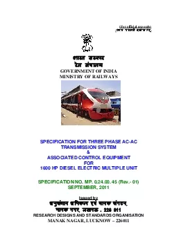
dsoy ljdkjh izksx gsrqHkkjr ljdkj jsy eaky GOVERNMENT OF INDIA MINISTRY OF RAILWAYS SPECIFICATION FOR THREE PHASE ACAC TRANSMISSION SYSTEM ASSOCIATED CONTROL EQUIPMENT FOR 1600 HP DIESEL ELECTRIC MUL ID: 875030

system traction motor control traction system control motor inverter engine details rdso power case type equipment auxiliary spec rev

Share:

Link:

Embed:

Download Presentation from below link

Download Pdf The PPT/PDF document "For official use only" is the property of its rightful owner. Permission is granted to download and print the materials on this web site for personal, non-commercial use only, and to display it on your personal computer provided you do not modify the materials and that you retain all copyright notices contained in the materials. By downloading content from our website, you accept the terms of this agreement.


Presentation Transcript

1 (For official use only) ( dsoy ljdkjh
(For official use only) ( dsoy ljdkjh iz;ksx gsrq ) Hkkjr ljdkj jsy ea=ky; GOVERNMENT OF INDIA MINISTRY OF RAILWAYS SPECIFICATION FOR THREE PHASE AC-AC TRANSMISSION SYSTEM & ASSOCIATED CONTROL EQUIPMENT FOR 1600 HP DIESEL ELECTRIC MULTIPLE UNIT SPECIFICATION NO. MP. 0.24.00. 45 (Rev.- 01) SEPTEMBER, 2011 Issued by vuqla/kku vfHkdYi ,oa ekud laxBu] Ekkud uxj] y[kuÅ - 226 011 RESEARCH DESIGNS AND STANDARDS ORGANISATION MANAK NAGAR, LUCKNOW – 226011 RDSO SPEC. No.MP.0.2400.45 (Rev.- 01) Annexure - III EQUIPMENT TEST SPECIFICATION 1. Traction Motor IEC - 60349 (Pt - 2)

2 2. Auxiliar
2. Auxiliary machine IEC - 34.1 3. Power inverter IEC - 61287, 4. Power Rectifier IEC - 60411, 5. Relays & Contactors IEC - 60337, 60157, 60158, 77 6. Control cubicle IEC - 68-2-14 7. Traction Alternator IEC - 60349 (Pt - 1) 8. Control Electronics IEC - 60571

3 9. Equipment Blowers
9. Equipment Blowers BS - 848 10. Electromagnetic Compatibility EN : 50121-3-2 (CENELEC) (Rolling Stock – Apparatus) 11. Electromagnetic Compatibility EN : 50121-2 (CENELEC) (Emission of the whole railway system to the outside world) 12. Train Communication Network IEC-61375-1 Page 29 of 29 RDSO SPEC. No.MP.0.2400.45 (Rev.- 01) 10. Microprocessor Controls Make and type, details of traction alternator excitation controls, analog / binary inputs / outputs signals, vehicle bus, train bus interface, CPU details s. Details of interface with the traction inverter system and braking system. Details of protection and indication system. Details of adhesion control system. Overall dimension / 11. Traction Gears Basic rack, number of teeth, module, pressure angle, helix angle (i

4 f any), profile displacement (x.m), cent
f any), profile displacement (x.m), center distance between mating gears, quality & accuracies of gear teeth and other related information. Material specification, chemical composition and mechanical properties, forging ratio etc. Heat treatment process adopted for hardening the gears i.e. case hardening / Hardness at tip, flank and root of se depth of case hardened gears and hardness distribution of cross section in case of induction hardened gears shall also be furnished. 12. Micro controller based governor for engine control of display screen, fault diagnostics and data logging features. Page 28 of 29 RDSO SPEC. No.MP.0.2400.45 (Rev.- 01) 4. Auxiliary machines Make and type of auxiliary machine, starting current and torque, torque-speed characteristics at various voltages, continuous rated power, voltage, current & speed; type of enclosure, details of cooling fan, air gap, details of winding and insulation, conductor size, current density, t

5 ype of conductor insulation, details le
ype of conductor insulation, details lead wire, terminals and terminal block, material of core stampings, details of bearings including L10 life and lubrication schedule, overall dimensions, weight, evaluation criteria and test programme, type and routine tests(if conducted) 5. Auxiliary Inverter(if offered) All relevant details as in case of main traction inverter. The auxiliary power as well as the reserve available for use in future shall be clearly stated. 6. Auxiliary Drive for blowers The technical details and controls/protection between AC supply to the terminals of the AC drive machines shall be submitted. 7. Master controller Make and type, rated current, making and braking current, position of reverser and throttle handle, details of cam and auxiliary interlocks, overall dimensions, weight, mechanical and electrical endurance test data. 8. Contactors Make and type, rated voltage and current, making and braking capacity, number of

6 auxiliary contacts with control circuit
auxiliary contacts with control circuit voltage, magnet valve and coil details, overall dimensions, weight, mechanical and electrical endurance test data. 9. Relays Make and type, rated current and voltage, range of setting, rated control voltage, rating of contacts, details of material of the contacts, type of enclosure, temperature rise limit, indication system provided, overall dimensions, weight and mechanical and electrical endurance test data. Page 27 of 29 RDSO SPEC. No.MP.0.2400.45 (Rev.- 01) Annexure - II Following data/details pertaining to el 1. Alternator cooling, details of insulation. 2. Traction Inverter Make and type, number of inverter cubicles, nominal input voltage and current, continuous output rating, maximum phase to phase output voltage at nominal input voltage, nominal output current at nominal input current, maximum output frequency, arrangement and details of IGBT devices (Manufacturer's data

7 sheet shall be furnished), declared dut
sheet shall be furnished), declared duty cycle rating, thermal characteristics of devices and heat sinks, details of cooling requirements/arrangement, maximum operating junction temperature of devices under worst operating conditions, safety margin, evaluation criteria and type test programme, protection and indication scheme, overall dimensions and weight. Technical details of DC link capacitors and any other filter/choke offered by the tenderer for fitment at the DC link . 3. Traction motor Make and type, continuous rating, one hour rating and short time rating, design/test/service speeds, starting current and duration, current ratings for various operating voltages, gear ratio, traction motor characteristics under different voltage conditions, details and data of windings including method of impregnation and varnish used, estimated temperature rise in windings, bearings etc., cooling arrangement including ducting details, rating under design of the bearings i

8 ncluding L10 life and lubrication scheme
ncluding L10 life and lubrication scheme, details of data for motorette test, evaluation criteria and test programme, results of type and routine tests (if conducted), fits and clearances adopted, overall dimensions and weight of traction motor, detailed design features of suspension roller bearings(if provided). Page 26 of 29 RDSO SPEC. No.MP.0.2400.45 (Rev.- 01) generally be conducted in accordance with relevant IECs as mentioned at annexure - III However, if the tenderer proposes a different test scheme, the same can be examined by RDSO on provision of alternative test procedures submitted by the tenderer. 17.3 The supplier shall submit detailed type and routine test programs to RDSO for approval. RDSO may also decide to carry out some tests on any one or all the equipment, which are not covered by relevant IEC specifications. Tests shall be carried out as per mutually agreed test program and the total cost shall be borne by the manufacturer. 17.4 The prototyp

9 e of Alternator, Traction Motor, Inverte
e of Alternator, Traction Motor, Inverter/Rectifier/TCC and vehicle control microprocessor will be tested by RDSO representative(s) at the manufacturer’s premises. All facilities for carrying out the prototype test should be made available by the firm. After successful type test and fitment on the DEMU, the equipment will be kept for field trials for a period of three months. All the modifications required Type test will be performed on one prototyp If mutually agreed between manufactu Subject to agreement between RDSO and Major modification of equipment, which is likely to affect its functionality or performance. Failure or major performance variations established during type or routine testing. Resumption of production after an interruption of more than two years. Page 22 of 29 RDSO SPEC. No.MP.0.2400.45 (Rev.- 01) 16.0 DOCUMENTATION 16.1 Following documents shall be submitted by each tenderer along with the offer for evaluation: (

10 a) Functional description of the complet
a) Functional description of the complete system. (b) Clause by clause complianc (c) Salient features and advant (d) Details of technical support and training offered. 16.2 Following documents shall be submitted by the successful tenderer, before commissioning of the equipment on DEMU: (a) Technical documentation explai (b) Vehicle Control System schematics. (c) Layout and mounting drawings of in (d) Drawings of each sub-syst (e) Technical data sheet of a (f) Cooling system details. (g) Details of enclosures provided. (h) Details of lubricants. (i) Procedure for user settable par (j) Maintenance and trouble shooting (k) Recommended list of spares for 3 years. (l) List of special tools, ji (m) Modifications needed in the exis 17.0 TESTING & INSPECTION 17.1 Type and routine tests of the individual equipment of AC traction system shall be conducted separately. Complete AC/AC system shall also be tested after its installation on DEMU. per IEC-60571

11 whereas traction alternator and tractio
whereas traction alternator and traction motors shall be Page 21 of 29 RDSO SPEC. No.MP.0.2400.45 (Rev.- 01) Time delay feature – A suitable time delay shall be provided in low oil pressure shutdown system at various notch speed steps to enable the engine driven lube oil pump to build up the requisite lube oil system pressure while starting the engine. A manual button, which would have to be reset after an LOPS shutdown has occurred, must be provided. Fail–safe feature – The governor shall be provided with fail safe feature so as to cause shutdown of the diesel engine by pulling the fuel racks to “NO FUEL” position in case of malfunctioning of the governing equipment. Multiple Unit (MU) Operation – The Governor shall have provision to enable multiple unit operation of the DEMU. 14.4 A suitable display screen for status of engine parameters shall be provided. The micro controller based engine governor shall provide suitable di

12 agnostic facility to carry out trouble s
agnostic facility to carry out trouble shooting for detecting the problematic areas / locations in case of faulty operation of the governor. In addition, facility for fault logging system shall be provided to register fault messages with date and time stamp. It shall be possible to easily retrieve the fault messages on a laptop / PC based computer. 15.0 TORSIONAL VIBRATION ANALYSIS mass moment of inertia, stiffness of different shafting, etc. Material 15.2 Verification of torsional matching of the equipment offered with other equipment shall be done by RDSO by carrying out detailed torsional 15.3 The manufacturer shall be prepared to carry out modifications in the design of offered equipment if considered necessary from the torsional matching considerations. Page 20 of 29 RDSO SPEC. No.MP.0.2400.45 (Rev.- 01) 13.5 USER SETTABLE PARAMETERS For flexibility of operation and future upgrades in the traction equipment, it is desirable to provide us

13 er configurability for various control p
er configurability for various control parameters like currents, voltages, horse powers, temperatures, pressures and speeds of the traction equipment. It shall be possible to configure these parameters through a laptop PC. A menu driven easy to use application software shall be provided for loading on the Laptop PC for this purpose. Password 14.0 ENGINE GOVERNOR 14.1 The tenderer shall coordinate with the engine supplier M/s Cummins Ltd. to offer a suitable micro controller based engine governor. Alternatively Governor can be an integral part of the Vehicle Control Computer. This Governor should be capable of interacting with the main vehicle control microprocessor. The governor shall be suitable for providing eight engine speed steps (notches), the idle being 700 RPM and maximum speed being 1800 RPM. It shall have provision to alter any notch speed, if so required in nor shall be required to maintain a stable engine speed i.e. free from hunting at each notch pos

14 ition in both conditions – with or
ition in both conditions – with or without load. It shall also maintain constant power output of the engine at each notch position. For intermediate notch positions, the time taken to adjust the engine rpm shall be in the same proportion. In case of engine rpm increase beyond a preset value, an engine over speed trip facility shall be provided to effect engine shutdown by way of bringing fuel rack to zero. Suitable Fuel Oil Pressure (FOP) and Lube Oil pressure (LOP) Transducers shall be provided. 14.2 The governor shall be provided with facility to adjust following parameters of the engine through software: Notch wise engine speed. Notch wise minimum lube oil pressure for engine shutdown. Maximum permissible fuel rack at each notch. Maximum permissible fuel rack in Over speed trip setting. Governor response. Load control timing from max. to min. position and from min. to max. position. PID parameters. ng safety features/devices in the Low lube

15 oil pressure shutdown. Page 19 of 29
oil pressure shutdown. Page 19 of 29 RDSO SPEC. No.MP.0.2400.45 (Rev.- 01) 11.0.10 Preferably forced air cooling shall be used for inverters. It is preferable that cooling requirement of complete inverter system be met by blowers that are located inside the inverter cabinet(s) itself. \ 11.0.11 the weight of the Inverter and rectifier combined should be approximately 2 tons. 11.1 GENERAL POINTS FOR TRACTION INVERTER DESIGN 11.1.1 Inverter shall be of PWM type with high switching frequency to obtain near sinusoidal waveform and reduce current harmonics even in the lower speed region of traction motor. The harmonics of the output waveform of inverter shall be controlled to minimize the traction motor torque pulsations, traction motor heating and also to provide constant and high adhesion between wheel speed range of the DEMU. 11.1.2 The components and technology used shall ensure very high efficiency of the inverter system. Typical efficiency of about 98% is

16 preferred. Manufacturer shall furnish t
preferred. Manufacturer shall furnish the expected efficiency with respect to DEMU load/speed. 11.1.3 For semi conductor devices a safety margin of 25% on the ratings for current and voltage under worst operating conditions shall be provided and established through calculations. 11.1.4 Inverter system shall be provided with following features to minimize possibility of trains being stalled on the section: (a) In case of axle unit (b) Suitable margin shall be provided in 11.1.5 Inverter electronics should be TCN compatible. All communication interfaces should be TCN compatible as per IEC-61375-1. However, if it is not possible to design TCN compatible inverter control system having proper functional interface with vehicle control system, then the alternative Page 14 of 29 RDSO SPEC. No.MP.0.2400.45 (Rev.- 01) control system and in case of inverter cut out, inverter control system shall be designed to automatically reduce DEMU power adequately so that re

17 maining inverters and motors are not ove
maining inverters and motors are not overloaded and the DEMU is able to reach up to destination with reduced power. DEMU power shall be reduced in proportion to the number of traction motors cut out at that time. 11.0.5 Inverter Protection System shall be used to protect the inverters from over voltage and over current conditions on supply as well as load side. Protection shall be achieved by turning OFF the traction alternator excitation by vehicle control system in case current or voltage exceeds a pre-set value. An alternative proven and reliable protection system may also be offered by the tenderers giving full justification of the offered scheme. 11.0.6 The proposed traction inverter system shall be capable of withstanding dielectric test voltages as per IEC-61287-1(for power circuit) and IEC-60571-1(for control circuit). The traction inverter system shall be designed for following protection class: (a) For phase modules

18 : IP20 (b) For electronic compar
: IP20 (b) For electronic compartments : IP54 11.0.7 The main power semiconductor device used for switching shall be Insulated Gate Bipolar Transistor (IGBT) with sufficient PIV rating. The IGBT module may contain external or internal protection circuits and gate drive circuits. The complete system shall be designed as simple as possible with reduced number of components without compromising reliability and efficiency. The devices offered should be field proven. The detailed characteristics of the devices along with details of gate drive circuits and protection circuits used shall be furnished in the offer. 11.0.8 Suitable temperature sensors shall be provided so that temperature of phase modules / IGBT modules can be continuously monitored by the control system. In case of over temperature, traction motor torque should be / IGBT modules at safe operating conditions. Additionally, IGBT modules should preferably be provided with a built-in self-protection f

19 unction to avoid failure on over tempera
unction to avoid failure on over temperature, in case of failure of temperature sensor. 11.0.9 The proposed inverter system shall be modular in construction so as to facilitate ease of maintenance and replacement. In case of any fault, removal and replacement of phase modules should be easy. Tenderer shall confirm support for obsolescence of all semi conductor devices for a minimum period Page 13 of 29 RDSO SPEC. No.MP.0.2400.45 (Rev.- 01) to withstand internal short circuits due to string failure condition and short circuit across DC link. Cooling air requirement for the rectifier shall be indicated by the tenderer in the offer. 10.3 The devices used in the rectifier assembly shall preferably be of a standard type of a reputed make such that, in case of urgency, the purchaser can interchange these devices with commercially available devices of another make. 10.4 The layout of components inside the rectifier assembly shall provide for easy accessibility

20 and replacement of the failed components
and replacement of the failed components during maintenance without having to remove large number of other healthy components. Each component shall be clearly marked to indicate type, nomenclature and rating. 10.5 All the components such as diodes, heat sinks, fuses, micro switches, snubber capacitors/resistors etc. and their mounting arrangement shall be designed to withstand vibrations and 11.0 TRACTION INVERTER SYSTEM 11.0.1 Proposed traction inverter system may preferably have four inverters using one inverter individually for each motor. Alternatively, a configuration of two traction inverters may also be offered. In this case each traction inverter shall drive traction motors on one bogie. Input supply for all the traction inverters shall be the same DC link. 11.0.2 The basic control philosophy for the induction motor shall be such as to achieve best suited results for traction application like minimum device losses, high dynamic response, stable constan

21 t speed operation, fast acting slip/slid
t speed operation, fast acting slip/slide control etc. Direct Torque Control, Vector Control, Slip Frequency Control etc. are some of the popular control strategies used for traction drives. Vector control system is not used in the existing DEMUs. The tenderer shall furnish the details of control strategy duly describing its merits. 11.0.3 The software of the inverter control system shall be fully compatible with the Vehicle control software including closed loop propulsion control, slip slide control, exchange of temperature data, fault diagnosis etc. The inverter system should have its own protection and control logic, which it should also be able to communicate with the vehicle control software in the event of a fatal failure to initiate a protective shutdown of the DEMU. Damage to IGBT ll be prevented in case of a short circuit at the load end. 11.0.4 Motor cut out facility shall be provided to isolate defective traction motor(s) in case of any fault. In case

22 axle control philosophy is followed, ea
axle control philosophy is followed, each defective traction motor can be isolated individually. In the event of bogie Page 12 of 29 RDSO SPEC. No.MP.0.2400.45 (Rev.- 01) 8.2 The machine shall be designed such that the 'hot spot' temperature under any condition of loading in stator winding does not exceed the average temperature of that winding (measured by resistance method) by more than 15 deg.C. 8.3 The manufacturer shall provide maximum possible margin in temperature rise for prolonged life of the traction machines after taking into consideration the system of insulation adopted and environmental conditions prevailing on Indian Railways. 9.0 AUXILIARY MACHINES DRIVE a) Auxiliary machines drive shall be si Traction Engine cooling : Hydrostatic drive Engine room ventilation ; Hydrostatic drive Compressor : Belt drive Auxiliary alternator : Belt drive (for controls and light, fan etc.) Auxi

23 liary alternator : Engine
liary alternator : Engine mounted belt driven (for starter battery charging): b) Alternatively tenderer may offer auxiliary machine drive as follows: Solid state Auxiliary Power Control (APC) for supplying auxiliary power for battery charging, controls, light, fan, rectifier blower motor etc. The APC shall draw power from Traction Alternator. The tenderer has an option to provide an APC of higher rating to drive motor driven compressor / electric motor driven radiator fan / ventilation fan or all the 3 in addition to the items specified in Sl no.8(a). In case this option is exercised, the vendor shall submit a suitable design of a proven electric compressor and radiator fan. The design shall be cleared by RDSO. 10.0 POWER RECTIFIER 10.1 The power rectifier shall be a 3-phase bridge using silicon diodes suitable for rectifying the 3-phase AC output of traction alternator throughout the range of operation of the alternator. More t

24 han one bridge units may be connected in
han one bridge units may be connected in parallel depending upon requirement. 10.2 Proposed rectifier shall have sufficient margin in continuous / short time ratings and surge withstanding capability. Also, it shall have adequate margin Page 11 of 29 RDSO SPEC. No.MP.0.2400.45 (Rev.- 01) 7.3 Suitable arrangement for sensing of the motor temperature shall be provided to allow microprocessor based controls to sense and take required action to prevent motor failure. 7.4 The motor shall be designed so as to be capable of withstanding voltage fluctuations and other conditions caused by stalling and wheel slip under difficult operational conditions. 7.5 Extreme adverse environmental conditions as stated in clause 3.0 and vibrations due to average track conditions should be taken into consideration during the design of the motor. 7.6 The traction motor shall operate satisfactorily over the entire range of loading with ripple/harmonic currents impose

25 d from the supply system (comprising of
d from the supply system (comprising of alternator, rectifier, inverter, etc.). The manufacturer shall conduct necessary tests on the traction motor to establish compliance with this requirement. 7.7 The traction motor shall be of a high voltage and low current design such that it is compact. The max. voltage rating of the traction motor shall be commensurate with the alternator/inverter voltage rating. hall not exceed 3000 rpm. Traction 7.9 The motor efficiency at continuous rating shall not be less than 93%. 7.10 The weight of the traction motor should be approximately 2 tons. 7.11 Gearcase The gearcase shall be of sturdy and lightweight construction and shall be adequately supported through the traction motor frame to prevent dropping down under the most severe vibration that may be generated due to adverse track conditions. 7.12 Traction Gears Traction gears and pinion shall be 8.0 INSULATION SYSTEM FOR TRACTION MACHINES 8.1 The insula

26 tion scheme for various electrical machi
tion scheme for various electrical machines offered should be class 200 or better. Page 10 of 29 RDSO SPEC. No.MP.0.2400.45 (Rev.- 01) case suitable for input supply from traction converter(s). 8. a) Auxiliary machines drive shall be similar to that of the existing 1400 HP DEMU. Alternatively, solid state Auxiliary Power Control (APC) for supplying auxiliary power for battery charging, controls, light, fan, rectifier blower motor b) The tenderer has an option to provide an APC of higher rating to drive electric compressor / electric motor driven an or all the 3 equipments in addition to the items specified in Sl no.8(a). In case this option is ex c) The APC shall draw power from Traction Alternator. 1 set 9. a) Air Compressor with other accessories, The compressor shall be Belt driven. b) Alternatively a motor driven compressor may also be draw power from the APC (Auxiliary power converter). The compressor shall be of a 1 No. 10. All the p

27 ower contactors, MCB’s, relays etc.
ower contactors, MCB’s, relays etc. 1 set 11. Battery: a. 24 V, 500 AH for engine starting b. 110 V supply of suitable 120 AH capacity for controls 1 set 1 set 12. Speed indicator gauge on the Driver Desk 1 set 13. Driver Desk including all accessories and excluding EP light, head light, tail light and fire alerter. 1 set 14. PC/Laptop based software tool for downloading the fault data packs, viewing and changing the user settable parameters along with user license 1 No. Page 4 of 29 RDSO SPEC. No.MP.0.2400.45 (Rev.- 01) 1.0.6 ‘AAR’ means Associat 1.0.7 ‘UIC’ means Union International Des Chemins defer (International Union 1.0.8 ‘IRS’ means I 1.0.9 ‘IR’ means Indian Railways. 1.0.10 Throughout this spec .1 Horse Power (HP) shall be taken as metric horse Power, i.e. 75 kg metre/sec. .2 Tonnes (T) shall be taken as metric ton i.e. 1000 kg. 2.0 SCOPE Scope of supply of equipment

28 for each unit shall be as under: Sr.
for each unit shall be as under: Sr. No. Equipment Description Quantity per 1. CIL make KTTA – 50 L4 fuel efficient diesel engine, capable of producing 1600 hp (under standard condition.) with either GAC or PG Woodward actuator, engine driven alternator for charging battery for engine cranking, hydrostatic cooling as in existing design, Fuel 1 no. 2. Traction Alternator to be directly coupled to CIL make KTTA – 50 L4 diesel engine. 1 No. 3. Base Rail arrangement with mounting brackets & bolts for mounting Engine and alternator. 1 set 4. IGBT based traction converter system including power rectifier, DC link and associated controls (Hardware and Vehicle Control System 2 nos. or 4 5. Microprocessor based Vehicle Control System (Hardware and software) along with all control, protection and indication equipment required for proper functioning of the DEMU. This shall be compatible with other equipment on 1 No. 6. Microprocessor based en

29 gine governor. This shall interface with
gine governor. This shall interface with Microprocessor based Vehicle Control System. 1no. 7. Three- p hase induction motors with g ear wheel and g ear 4 Nos. Page 3 of 29 RDSO SPEC. No.MP.0.2400.45 (Rev.- 01) The manufacturer is expected to prov The specification has been prepar Performance of 3-phase AC-AC DEMU Offers from only those tenderers, who have developed and have experience system shall be accepted. Therefore, tenderers must submit Tenderer shall have manufacturing, a 1.0 DEFINITIONS 1.0.1 ‘RDSO’ means Research Designs 1.0.2 ‘ICF’ means Integral 1.0.3 ‘BG’ means 1676 mm gauge, referred to as Broad Gauge. 1.0.4 ‘IEC’ means International Electro-technical Commission. 1.0.5 ‘IS’ means Indian Standard. Page 2 of 29 RDSO SPEC. No.MP.0.2400.45 (Rev.- 01) SPECIFICATION FOR THREE PHASE AC-AC TRANSMISSION SYSTEM & ASSOCIATED CONTROL EQUIPMENT FOR 1600 HP DIESEL ELECTRIC MULTIP

30 LE UNIT 0.0 Foreword Diesel Ele
LE UNIT 0.0 Foreword Diesel Electric Multiple Units are se The main features of DEMU are as follows: Fast and frequent service. No need for reversals at the terminals as it can be driven from either end. High acceleration. Low capital and maintenance costs. Efficient use of rolling stock. Electro-pneumatic Brakes At present, Diesel Electric Multiple 0.3 This specification has been prepared for development of a proven and modern 3-phase AC-AC transmission system with microprocessor based controls for the Indian Railway's 1600HP BG Diesel Electric Multiple Unit. 0.4 AC-AC transmission system and allied microprocessor based controls shall be used with M/s Cummins make KTTA-50-L4 diesel engine and allied mechanical systems to manufacture 1600HP AC-AC BG DEMU. 0.5 The equipment shall incorporate features to ensure high availability of DEMU, low maintenance requirements, high reliability in operation and excellent transmission efficiency. Page 1