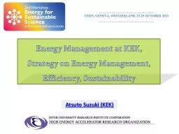
/
Atsuto Suzuki (KEK) Energy Management at KEK, Atsuto Suzuki (KEK) Energy Management at KEK,

Atsuto Suzuki (KEK) Energy Management at KEK, - PowerPoint Presentation

blindnessinfluenced
blindnessinfluenced . @blindnessinfluenced
Follow
342 views
Uploaded On 2020-06-17

Atsuto Suzuki (KEK) Energy Management at KEK, - PPT Presentation

Strategy on Energy Management Efficiency Sustainability Outline Energy Management at KEK Improve Efficiency of Power Consumption in Accelerator Operation 21 How to Improve RF Efficiency ID: 780340

power energy cpd klystron energy power klystron cpd beam collector electron efficiency potential dump ilc improve amp voltage management

Share:

Link:

Embed:

Download Presentation from below link

Download The PPT/PDF document "Atsuto Suzuki (KEK) Energy Management at..." is the property of its rightful owner. Permission is granted to download and print the materials on this web site for personal, non-commercial use only, and to display it on your personal computer provided you do not modify the materials and that you retain all copyright notices contained in the materials. By downloading content from our website, you accept the terms of this agreement.


Presentation Transcript

Slide1

Atsuto Suzuki (KEK)

Energy Management at KEK,

Strategy on Energy Management, Efficiency, Sustainability

Slide2

Outline

Energy Management at KEK

Improve Efficiency of Power Consumption in Accelerator Operation

2.1 How to Improve RF Efficiency

2.2 How to Save Power in Cryogenics

2.3 How to Recover Beam Dump Energy

Improve Power Storage to Reuse

Summary

Slide3

Energy Management at KEK

Slide4

Daily Management at KEK

: Saving Power Consumption

Slide5

J-PARC

Energy Storage for Power Fluctuation Compensation

a

t J-PARC MRMR

Power Amplitude of

J-PARC-MR

Operation

Cycle

J-PARC MR

Reputation (sec.)

3.64

Power (MW)

105

Line Voltage (kV)

66/22/6.6

Compensation Type

Fly Wheel : 51 MVA

SMES

: 90 MVA

A

MW

(1 – 4 sec. cycle)

Developing new MGs with large capacitor energy storage:

F. Kurimoto’s talk

Slide6

20 MJ Advanced

Large

Liquid Crystal plant in Kameyama since 2003

200 MJ Kinetic Energy Storage

(Fly Wheel)in Okinawa

Fly -Wheel and SMES Status in Japan

Slide7

Improve Efficiency

of

Power Consumption

in

Accelerator Operation

s

erious

i

ssue for ILC

Slide8

ILC 500

GeV

Total Power

:~200 MW

Improve efficiency

Increase recovery

Infrastructure : 50 MW

RF System : 70 MW

Cryogenics : 70 MW

Beam Dump : 10 MW

200 MW

l

oss

r

ate

50 %

: 25 MW

50

% :

35

MW

9

0

%

:

60

MW

100 % : 10 MW

130 MW

Power Balance of Consumption and

L

oss in ILC

O

bligation

to Us

Slide9

2.1 How to Improve RF Efficiency

R&D of CPD (Collector Potential Depression) Klystron

CPD is an energy-saving scheme that recovers the kinetic energy of the spent electrons after generating rf power.

Conventional

collector

Schematic diagram of CPD

collector

Slide10

Simplified Schematic

Concept

Potential denotes the electron potential energy, eV. For simplicity, input and intermediate cavities are omitted here and the anode potential is set to zero.

Potential & Electron Energy

Cathode

Anode

Output cavity

Collector

RF

Potential in the Klystron

Electron Energy

With CPD

E

0

E

c

CPD gap

U

k

U

c

E

1

Potential & Electron Energy

Cathode

Anode

Output cavity

Collector

RF

Potential in the Klystron

Electron Energy

Without CPD

E

0

U

k

U

c

E

c

E

1

Efficiency of RF Conversion (40-50) %

Heat Loss

Beam Deceleration

Energy Recovery/Reuse

Slide11

(I) Energy spread

The spent electron beam has large energy spread through electromagnetic interaction in the cavities. Therefore, the collector potential cannot be increased beyond the lower limit of energy distribution of the spent electron beam, otherwise backward electrons hit the cavities or the gun, and then deteriorate the klystron performance.

Issues must be addressed for CPD Klystron

Saturated: 1 MW out

Unsaturated: 200 kW out

E

0

= 90keV

E

0

= 90keV

(II) Pulse-to-DC conversion

T

he spent electron beam is longitudinally bunched, so that

pulsed voltage is induced on the collector

.

A

n

adequate pulse-to-DC converter

has to be implemented.

(III) RF Leakage

CPD

klystron has to be equipped with an

insulator between the collector and the body column

in order to apply CPD voltage to the collector. Thus, it would be possible for the CPD klystron to

leak

rf

power

out more or less from the insulator.

Ceramic Insulator

Output Coupler

Collector

Slide12

Present Status of R&D

R&D Schedule

2013.3: Modification of an existing klystron to CPD klystron (already done)

2014.3: until then, preparation and commissioning of the test station

~2014: Verification of klystron operation without CPD

~2015: Measurement of

rf

leakage from the gap between the body column and the collector (with no CPD voltage applied)

Measurement of induced pulse voltage on the collector with CPD

~2017: Test of rectification by Marx circuit

Integration test of the proof-of-principle of CPD operation

Recycled components

electron gun

input cavity

intemediate

cavities

Newly fabricated components

collector

ceramic insulator

output cavity

output coupler

Target

proof-of-principle of CPD in the unsaturated region (a maximum

rf

power of 500 kW) using a KEKB 1.2MW-klystron

80 % efficiency

Slide13

Multi(6) – Beam Klystron (MBK) for 26 Cavities for ILC

Frequency1.3 GHz

Peak power10 MWPulse width1.6 msRep. rate5 HzAverage power

78 kWEfficiency65 %

Gain

47dB

BW (- 1dB)

3 MHz

Voltage

120 kV

Current

140 A

Lifetime

40,000 h

The design goal is to achieve 10 MW peak power with 65 % efficiency at 1.5

ms

pulse length at 10 Hz repetition rates.

MBK has 6 low-

perveance

beams operated at low voltage of 115 kV for 10 MW to enable a higher efficiency than a single-beam klystron.

Slide14

Completely Old/New Idea for Klystron

Synchrotron Radiation Electron Tube

RF output

Cathode

Synchrotron radiation

from small bend

Bunched

Electron Beam

1.3GHz Electron Gun

Klystron

> 90% efficiency (small transient time factor by short bunch)

Stabled by space charge limit operation

Drivn

from low charge low energy 1.3GHz electron beam

(1/10 klystron ?)

Very low cost and long lifetime

Low cost beam line

No switch, only HV & capacitor

Advantages

Slide15

2.2 How to Save Power in Cryogenics

Cryogenics/

Stirling Cryocooler

High temperature operation

Klystron collector

RF Dummy load

Slide16

Multiple

Stirling

Cooling System

2 Stage-Stiling Cryocooler1st stage

2nd stage

t

hermal link

compressor

c

old head

Slide17

2.3 How to Recover Beam Dump Energy (

10 MW)

Recover Beam EnergyReduce Radio-Activation

Slide18

Noble Gas

DumpAbout 1km of

a noble gas (Ar looks the most promising) enclosed in a water cooled iron jacket (transport the heat).This gas dump design may ease some issues such as radiolysis and tritium production.Issue : particle beam heating of the gas and ionization effects.

Water Dump

Water Vortex Dump (25 m long x 15 m height for 1 TeV)SLAC Dump

f

or 800 kW

Issue

: shock wave management

Issue : management of tritium gas

and

tritiated

water in vapor form

Slide19

The deceleration distance in the

underdense

plasma is 3 orders of magnitude smaller than the stopping in condensed matter.The muon

fluence is highly peaked in the forward direction. Plasma Deceleration Dumping

10 cm for 100 GeV

Use Collective Fields of Plasmas for Deceleration

Slide20

here

&

ILC

s

T

≈ 50

m

m,

s

L

3

s

T

150

m

m

Collective Stopping Power for ILC

(e

lectron bunch)

L = 10

m for Li gas

Next Trials

Experiment of Proof-of-Principle

Deposit mechanism of Wake-Field energy

Slide21

3. Improve

:

Power Storage to Reuse

Slide22

Store the surplus

electric energy

as thermal energyStorage of Electric Energy as Heat in Iron

Electric Energy

100 MW x 1 0 hours

E = 100 M J / sec

x

3600 sec

/

hr

x 10

hr

= 3600 GJ

10 m

3 x 10

3

m

3

~ 1.7 GJ x ~ 5100 GJ

3000

10 m

10 m

Heat Capacity Iron vs. Water

Heat Capacity of Iron

Heat Capacity of Water

Storage of Thermal Energy

Slide23

h

ow to keep iron heat

ILC Tunnel

Blast Furnace

Fire

Brick

Slide24

4

.

Summary

ILC

Improve

E

fficiency

Recover

Energy

Reuse

Energy

Reuse

Energy

Stand Alone

Energy System

Slide25

The

muon fluence

is highly peaked in the forward direction.

Beam dump

m

Injection

Fixed

Field Alternating

Gradient

Accelerator

FFAG Ring

RF

Extraction

Extraction

 Usage

No Extraction  Decay

m