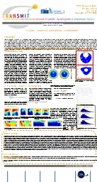
Authors Luca Müller Supervision by Alessandro Mapelli EPDTDD Yves Leterrier LTCEPFL The PMMA microScint Polymeric single layer of optical waveguides produced by in situ polymerization ID: 800244
Download The PPT/PDF document "DEVELOPMENT OF A PHOTO-POLYMERIC MICROFL..." is the property of its rightful owner. Permission is granted to download and print the materials on this web site for personal, non-commercial use only, and to display it on your personal computer provided you do not modify the materials and that you retain all copyright notices contained in the materials. By downloading content from our website, you accept the terms of this agreement.
Slide1
DEVELOPMENT OF A PHOTO-POLYMERIC MICROFLUIDIC SCINTILLATION DETECTOR
Authors:
Luca Müller
Supervision by:
Alessandro
Mapelli
(EP-DT-DD)
Yves
Leterrier
(LTC-EPFL)
Slide2The PMMA microScint
Polymeric single layer of optical waveguides produced by in situ polymerization
moulding
.It exploits total internal reflection (TIR) as working principle to guide the photons.Potential application: beam monitoring for hadron therapy
L. Müller EP-DT-DD (CERN)
2
Introduction: the context
Process: in situ polymerization molding.
Issues:Important thermal stressesThe polymerization process is time expensive (about 24h)
Material PMMA
I
ssues:
Important
chemical shrinkage
(
total 20%)
PMMA has a moderate radiation resistance
Slide3The UV photo-polymerization process (UV curing)L. Müller EP-DT-DD (CERN)
3
Introduction:
the UC curing process
Advantages:
High processing speed.
Low heat generation.
High product durability.
Low processing costs.Low energy process.Low organic emissions.
Disadvantages
Cure thickness limited.
Oxygen and moisture sensitivity.
Expensive initial investment.
Room temperature process: reaction activated with UV light
Process widely used for industrial applications (adhesives, coating, inks, photolithography, 3D printing, dental implants…) due to its high speed.
Slide4ObjectivesL. Müller EP-DT-DD (CERN)
4
Objectives
To
create a UV curing process for the PMMA.
To exploit the UV curing process for the production of two other polymers.To characterize the radiation resistance of these materials.To select the more suitable material for the production of the
microScint device.
Slide5The candidate materials
PMMA
L. Müller EP-DT-DD (CERN)
5
UV curing process determination
Sigma Aldrich catalogue
Acrylate resin
Epoxy siloxane resin
Sigma Aldrich catalogue
Marina A. Gonzalez
Lazo
, EPFL, 2015
Radical system
Linear polymer
Shrinkage: 20%
Refractive index=1.49
Transmittance=92%
Radical system
Crosslinked
polymer
Shrinkage: 4%
Refractive index=1.48
Transmittance=89%
Cationic
system
Crosslinked
polymer
Shrinkage: 2%
Refractive index=1.50
Transmittance=95%
Photo-acid generator
Slide6UV Curing: how does it work?L. Müller EP-DT-DD (CERN)
UV curing process determination
Cationic (e.g. epoxies)
Radical (e.g. acrylates)
A.Vitale
et al. 2014
UV curing technologies doctoral course, EPFL, 2016
6
Slide7Photo-initiator concentration:It controls the conversion degree, hence the physical properties (stiffness, density, transmittance…)
Dependence of the cure depth:
the molar absorptivity of the PI, c the PI concentration, d the light
pathlength
Polymerization parameters
L. Müller EP-DT-DD (CERN)
7
UV curing process determination
Slide8Light intensity:It controls the conversion rate, hence the reaction time.It controls the internal stress build up.
Polymerization parameters(2)
L. Müller EP-DT-DD (CERN)
8
UV curing process determination
Slide9Working schedule (1)
Definition of PI concentration:
Solution to tests:
MMA + 0.1 / 0.2 / 0.5 / 1%wt PIHBP CN2305 + 0.5 / 1 / 1.5 / 2%wt PIEpoxy-Siloxane oligomer + 0.5 / 1 / 1.5 / 2%wt PI
Definition of light intensity steps.Measurement techniques to employ:
Photo-rheology (mechanical properties evolution)Photo- Differential Scanning Calorimetry (Conversion degree and rate evolution)
Fourier Transform InfraRed spectroscopy (Conversion degree)Mickelson interferometry (shrinkage evolution)
Beam bending (internal stresses)
L. Müller EP-DT-DD (CERN)9UV curing process determination
Slide10Working schedule(2)
Irradiation at the PS (IRRAD) with 24GeV protons.
Dose calculated according to the radiative environment of CNAO (Centro
Nazionale di Adroterapia Oncologica):10^3
Gy ≈ 1 day10^4 Gy
≈ 30 days10^5 Gy
≈ 6 months10^6 Gy ≈ 1 year10^7
Gy ≈ 10 yearsCharacterization of:Refractive index -> Exploitation of TIRTransmittance -> Exportation of the photons
Tensile strength -> Structural performance L. Müller EP-DT-DD (CERN)10Irradiation tests
Slide11Thank you for your attentionAre there any questions?
L. Müller EP-DT-DD (CERN)
11
Slide12L. Müller EP-DT-DD (CERN)12
Work
Activity
Start week
End week
Timetable
Month
Feb.
March
April
May
June
July
Aug.
week
1
2
3
4
5
6
7
8
9
10
11
12
13
14
15
16
17
18
19
20
21
22
23
24
25
26
Theory
Choice of materials
1
3
Definition of radiation damage tests
1
3
Definition of shrinkage tests
1
3
Definition of scintillators compatibility tests
1
3
Definition of bonding and bonding strength tests
1
3
Practical
Polymerization of samples
4
9
Scintillators compatibility tests
5
9
Shrinkage measurements
5
9
Optical characterization (transmittance and ref. index)
5
16
Irradiation tests
10
16
Polymerization of samples for bonding tests
15
18
Bonding
17
18
Bonding strength tests
18
20
options
Microchannels samples production
17
22
Bonding of microchannels
17
22
Detector characterization
17
22
Thesis
Introduction
1
3
Chapter 1: State of the art
1
6
Chapter 2:Structural material polymerization
7
11
Chapter 3: Materials characterizations
12
16
Chapter 4: Radiation damage tests
4
20
Option
Chapter 5: Device characterization
18
22
Chapter 6: Conclusions and outlooks
22
26