/
Proc. of the EPRI Power Quality Issues & Opportunities Conference (PQA Proc. of the EPRI Power Quality Issues & Opportunities Conference (PQA

Proc. of the EPRI Power Quality Issues & Opportunities Conference (PQA - PDF document

briana-ranney
briana-ranney . @briana-ranney
Follow
423 views
Uploaded On 2015-08-05

Proc. of the EPRI Power Quality Issues & Opportunities Conference (PQA - PPT Presentation

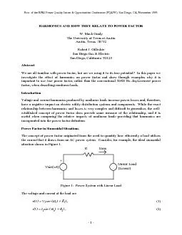
Irms Figure 1 Power System with Linear Load vtsin ot 1 1 itsin ot 1 2 Proc of the EPRI Power Quality Issues Opportunities Conference PQA93 San Diego CA Novem ID: 100640

Irms Figure Power System

Share:

Link:

Embed:

Download Presentation from below link

Download Pdf The PPT/PDF document "Proc. of the EPRI Power Quality Issues &..." is the property of its rightful owner. Permission is granted to download and print the materials on this web site for personal, non-commercial use only, and to display it on your personal computer provided you do not modify the materials and that you retain all copyright notices contained in the materials. By downloading content from our website, you accept the terms of this agreement.


Presentation Transcript

Proc. of the EPRI Power Quality Issues & Opportunities Conference (PQA’93), San Diego, CA, November 1993.HARMONICS AND HOW THEY RELATE TO POWER FACTOR W. Mack Grady The University of Texas at Austin Austin, Texas 78712 Irms Figure 1: Power System with Linear Load v(t)sin (  ot   1), (1) i(t)sin (  ot   1), (2) Proc. of the EPRI Power Quality Issues & Opportunities Conference (PQA93), San Diego, CA, November 1993. and are peak values of the 50/60 Hz voltage and current, and  and  are the relative phase angles. The true power factor at the load is defined as the ratio of average power trueavgavgrmsrms . (3) For the purely sinusoidal case, (3) becomes pftruepfdispPavgP2Q2 V12 I12 cos112 I12 =cos , (4) is commonly known as the displacement power factor, and where 1   is known as the power factor angle. Therefore, in sinusoidal situations, there is only one power factor because true power factor and displacement power factor are equal. For sinusoidal situations, unity power factor corresponds to zero reactive power Q, and low power factors correspond to high Q. Since most loads consume reactive power, low power factors in sinusoidal systems can be corrected by simply adding shunt capacitors. Sinusoidal Example Consider again the case in Figure 1, where a motor is connected to a power system. The losses incurred while delivering the power to the motor are . Now, while holding motor active and voltage 1rms constant, we vary the displacement power factor of the motor. The variation in losses is shown in Figure 2, where we see that displacement power factor greatly Losses - PU. of Nominal0.50.60.70.80.91Figure 2: Effect of Displacement Power Factor on Power System Losses for Sinusoidal Example (Note: losses are expressed in per unit of nominal sinusoidal case where 1.0 Proc. of the EPRI Power Quality Issues & Opportunities Conference (PQA93), San Diego, CA, November 1993.Power Factor in Nonsinusoidal Situations Now, consider nonsinusoidal situations, where network voltages and currents contain harmonics. While some harmonics are caused by system nonlinearities such as transformer saturation, most harmonics are produced by power electronic loads such as adjustable-speed drives and diode-bridge rectifiers. The significant harmonics (above the fundamental, i.e., the first harmonic) are usually the 3rd, 5th, and 7th multiples of 50/60 Hz, so that the frequencies of interest in harmonics studies are in the low-audible range. When steady-state harmonics are present, voltages and currents may be represented by Fourier v(t)sin (k , (5) i(t)sin (k , (6) whose rms values can be shown to be Vrms22 k1 Vkrms2k1 , (7) Irms22 k1 Ikrms2k1 The average power is given by cos 3avgwhere we see that each harmonic makes a contribution, plus or minus, to the average power. A frequently-used measure of harmonic levels is total harmonic distortion (or distortion factor), which is the ratio of the rms value of the harmonics (above fundamental) to the rms value of the THDVVkrms2k2 1rms 100%Vk2k2 V1 , (10) Proc. of the EPRI Power Quality Issues & Opportunities Conference (PQA93), San Diego, CA, November 1993. THDrms  100%100% . (11) Obviously, if no harmonics are present, then the THDs are zero. If we substitute (10) into (7), VVTHDrmsrmsV1100 IITHDrmsrmsI1100Now, substituting (12) and (13) into (3) yields the following exact form of true power factor, 1rms/100 /100 . (14) A useful simplification can be made by expressing (14) as a product of two components, 1rms /100 /100 and by making the following two assumptions: 1. In most cases, the contributions of harmonics above the fundamental to average power in (9) are small, so that Pavg P2. Since is usually less than 10%, then from (12) we see that 1rmsIncorporating these two assumptions into (15) yields the following approximate form for true avg11rms1rms /100 Because displacement power factor can never be greater than unity, (16) shows that the /100 . (17) Proc. of the EPRI Power Quality Issues & Opportunities Conference (PQA93), San Diego, CA, November 1993.Equation (17), which is plotted in Figure 3, provides insight into the nature of the true power factors of power electronic loads, especially single-phase loads. Single-phase power electronic loads such as desktop computers and home entertainment equipment tend to have high current distortions, near 100%. Therefore, their power factors are generally less than 0.707, even though their displacement power factors are near unity. Maximum True PowerFactor020406080100120140Figure 3: Maximum True Power Factor pftrue Versus On the other hand, three-phase power electronic loads inherently have lower current distortions than single-phase loads and, thus, higher distortion power factors. However, if three-phase loads employ phase control, their true power factors may be poor at reduced load levels due to low displacement power factors. It is important to point out that one cannot, in general, compensate for poor power factor by adding shunt capacitors. Only the displacement power factor can be improved with capacitors. This fact is especially important in load areas that are dominated by single-phase power electronic loads, which tend to have high displacement power factors but low distortion power factors. In these instances, the addition of shunt capacitors will likely worsen the power factor by inducing resonances and higher harmonic levels. A better solution is to add passive or active filters to remove the harmonics produced by the nonlinear loads, or to utilize low-Power factor measurements for some common single-phase residential loads are given in Table 1, where it is seen that their current distortion levels tend to fall into the following three categories: low ( 50%), high ( Proc. of the EPRI Power Quality Issues & Opportunities Conference (PQA93), San Diego, CA, November 1993.Table 1: Power Factor and Current Distortion Measurements for Common Single-Phase Residential Loads Load Type pfdisp THDI pfdist Ceiling Fan 0.999 1.8 1.000 0.999 Refrigerator 0.875 13.4 0.991 0.867 Microwave Oven 0.998 18.2 0.984 0.982 Vacuum Cleaner 0.951 26.0 0.968 0.921 Fluorescent Ceiling Lamp 0.956 39.5 0.930 0.889 Television 0.988 121.0 0.637 0.629 Desktop Computer and Printer 0.999 140.0 0.581 0.580 * Leading displacement power factor Nonsinusoidal Example Now, consider the situation shown in Figure 4, where the motor load of Figure 1 is replaced by a nonlinear load with the same Pavg. - R Irms Vsin(wt)+ Figure 4: Power System with Nonlinear Load Assuming that avg is constant, we vary the displacement power factor and compute the impact on system losses. The results are plotted in Figure 5, where it is seen that has a significant impact on system efficiency and that the efficiency is considerably less than in the sinusoidal case of Figure 2. Proc. of the EPRI Power Quality Issues & Opportunities Conference (PQA93), San Diego, CA, November 1993. Losses - PU. of Nominal0.50.60.70.80.91 Linear Load (From Figure 2)Nonlinear Load Figure 5: Effect of Displacement Power Factor on Power System Losses for Nonsinusoidal Example (Note: harmonic amperes held constant at the level corresponding to the following: THDdisp. Losses are expressed in per unit of nominal sinusoidal case where trueOther Considerations In the previous examples, we assumed that the resistance of the power system does not vary with frequency, so the losses are simply PIRRIIRlosskrmskrmsIn an actual system, however, resistance increases with frequency because of the resistive skin effect, so an ampere of harmonic current (above the fundamental) produces more loss than does an ampere of fundamental current. For typical wire sizes found in distribution systems, the resistance at the 25th harmonic may be 2 - 4 times greater than the 50/60 Hz resistance. Generally speaking, the larger the diameter of a wire, the greater the impact. This resistance increase is especially important in transformers, and it forms the basis upon which transformer derating calculations are made [1]. Another consideration is the affect of voltage harmonics on losses, which is even more complex than that of current. Studies by Fuchs, et al., [2] show that voltage harmonics can either increase or decrease losses in equipment, depending on their phase angles. Because of the belief that harmonic voltages and currents should be weighted according to frequency, McEachern [3] proposed the following generalized harmonic-adjusted power factor hpfPavgCkVkrmsk1 Ikrmsk1 . (19) Proc. of the EPRI Power Quality Issues & Opportunities Conference (PQA93), San Diego, CA, November 1993.He proposed several sets of and weighting coefficients, but there is not yet a consensus of Harmonics and power factor are closely related. In fact, they are so tightly coupled that one can place limitations on the current harmonics produced by nonlinear loads by using the widely-accepted concept of power factor, providing that power factor is used rather than displacementEquation (17) gives the limit on true power factor due to harmonic current distortion. Each corresponds to a maximum true power factor, so a limit on maximum true power factor automatically invokes a limitation on . Some examples are Desired Limit Corresponding Limit on - % on true 20 0.981 50 0.894 100 0.707 Efforts are presently underway to develop new power factor definitions, such as harmonic-adjusted power factor, that take into account the frequency-dependent impacts of voltage and In conclusion, even though power factor is an old and at first glance uninteresting concept, it is worthy of being "re-visited" because it has, in a relatively simple way, the potential of being very useful in limiting the harmonics produced by modern-day distorting loads. Acknowledgments We would like to acknowledge the Electric Power Research Institute, and especially senior project manager Mr. Marek Samotyj, for providing financial support for the study of harmonics and their relation to power factor. We would also like to thank Basic Measuring Instruments for supplying us with the harmonics-measuring equipment needed for our study. Finally, we would like to express our appreciation to Dr. David F. Beer, U. T. Austin, for his editorial assistance. References 1. J. C. Balda, et al., "Comments on the Derating of Distribution Transformers Serving Nonlinear Loads, " Proc. of the Second Int’l Conf. on Power Quality: End-Use , Atlanta, Georgia, Sept. 28-30, 1992, paper D-23. 2. E. F. Fuchs, et al., "Sensitivity of Electrical Appliances to Harmonics and Fractional Harmonics of the Power Systems Voltage," Parts I and II, vol. PWRD-2, no. 2, pp. 437-453, April 1987. 3. A. McEachern, "How Utilities Can Charge for Harmonics," Minutes of the IEEE Working Group on Power System Harmonics, IEEE-PES Winter Meeting, Columbus, Ohio, February 1, 1993.