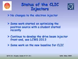
LCWS 2014 Belgrade October 6 th 10 th 2014 Steffen Döbert BERF No changes to the electron injector Some work started on optimizing the positron source with a student started recently ID: 290844
Download Presentation The PPT/PDF document "Status of the CLIC Injectors" is the property of its rightful owner. Permission is granted to download and print the materials on this web site for personal, non-commercial use only, and to display it on your personal computer provided you do not modify the materials and that you retain all copyright notices contained in the materials. By downloading content from our website, you accept the terms of this agreement.
Slide1
Status of the CLIC Injectors
LCWS 2014, Belgrade, October 6th-10th, 2014
Steffen Döbert, BE-RF
No changes to the electron injector
Some work started on optimizing the
positron source with a student started recently
Continue to develop the drive beam injector front end, see LCWS 2013
Some work on the new baseline for CLICSlide2
Positron source
Plan to have for the first time consistent simulations from the target to the damping ring and optimize the positron yield.
New Student Cafer Bayar joint us very recently and started to work.
Phase space after target, after AMD and at the end of the 200 MeV pre-injector
linac
using CDR parametersSlide3
Positron source
Very preliminary studies, playing with acceleration and deceleration scenarios. Increasing the solenoid field to 1 T instead of 0.5 T seems to help a lot. Is it feasible, affordable ?
Cafer BayarSlide4
CLIC DB front end,
Post CDR Project Major components under development, gun, SHB, PB, TW-
BuncherAs well as power sources, up to 100 kW , wide band solid state source at 500 MHz and 20 MW L-band klystron with 70 % efficiency (two prototypes have been ordered with Thales and Toshiba)
Gun
SHB 1-2-3
PB
TW-
Buncher
Acc. Structures
500 MHz
Modulator-klystrons,
1 GHz,
20
MW
~
140
keV
~
12
MeV
Diagnostics
~
3
MeVSlide5
Thermionic Gun designSlide6
New CLIC base line studies
Alternative layout:
w
ithout
positron driver
linac
and e
-
PDR, 2 GHz bunch spacing everywhere
Pre-injector
e
-
Linac
e
-
e
-
3300 ns
156ns
156ns
e
+
Positron production pulse
Save two rings, positron driver
linac
, and tunnel length (saving potential 200 MCHF)
Injector
Linac
Booster
Linac
2 GHz
e
-
DR
gun
PDR
e
+
DR
BC1
DC gun
target
6
GeV
2.86
GeV
0.2
GeVSlide7
Layout with
undulator
based positron source
IP
target
BDS
Main
Linac
Main
Linac
Injector
Linac
Booster
Linac
2 GHz
Pre-injector
e
-
Linac
e
-
DR
gun
e
+
DR
BC1
DC gun
target
6
GeV
2.86
GeV
0.2
GeV
Spin rotator
t
o main
linacs
Undulator
positron source
Undulator
350 m
2.86
GeV
linac
? 300m
BDS
Photons 300 m
~1000 m
t
o transfer line, DR
Main beam bypass line
f
rom injectors
PDR
Minimum scenario for upgrade to positron polarization and fully compatible with conventional layoutSlide8
U
ndulator based positron source
Consequences:
400 -1000 m more
linac
length (both sides ?)
Separate injector
linac
for positrons 2.86
GeV
t
ransfer line from the tunnel to the injector complex
Spin rotator before and after damping ring (needed anyway for any polarized scheme)
Gap in damping ring due the delayed beams
Main beam bypass around positron production
Coupling of the two beamsSlide9
How about a dedicated scheme ?
IP
BDS
Main
Linac
Main
Linac
Booster
Linac
6
GeV
e
-
DR
DC gun
2.86
GeV
BDS
PDR
e
+
DR
DR and injector at the end of each sideSlide10
Conclusion
For time being minimum effort going into the main beam injector studies due to lack of manpower and other priorities in the project
We feel it is not the most critical area for CLIC to work on
Some effort in developing the drive beam injector front end including the sophisticated power sources.
Wide band for sub-harmonic switching and very high efficiency for drive beam
Hopefully we can revive some work on the positron source with the new student
No conclusions yet for the new baseline