/
Fundamental of antenna Fundamental of antenna

Fundamental of antenna - PowerPoint Presentation

calandra-battersby
calandra-battersby . @calandra-battersby
Follow
400 views
Uploaded On 2015-11-07

Fundamental of antenna - PPT Presentation

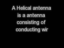
Name Mashhour j umah ID202322165 Welcome What is an antenna An antenna is an electrical conductor or system of conductors used for transmission and reception of electromagnetic waves ID: 186106

radio antenna antennas transmission antenna radio transmission antennas power line yagi reflector wave equivalent electromagnetic dipole satellite portion type

Share:

Link:

Embed:

Download Presentation from below link

Download Presentation The PPT/PDF document "Fundamental of antenna" is the property of its rightful owner. Permission is granted to download and print the materials on this web site for personal, non-commercial use only, and to display it on your personal computer provided you do not modify the materials and that you retain all copyright notices contained in the materials. By downloading content from our website, you accept the terms of this agreement.


Presentation Transcript

Slide1

Fundamental of antenna

Name: Mashhour jumahID:202322165

Welcome Slide2

What is an antenna?An antenna is an electrical conductor or system of conductors used for transmission and reception of electromagnetic

wavesTransmission

radiates electromagnetic energy into space

Reception

collects electromagnetic energy from

spaceSlide3

Antenna Fundamentals3

Radiation PatternsSlide4

Antenna FundamentalsRelationship between antenna gain and effective area G = antenna gain

Ae = effective areaf = carrier frequency

c = speed of light (» 3 ´ 10

8

m/s)

= carrier wavelength

Property of R Struzak

4Slide5

Types of antennaAntenna types: actually there are many types of Antenna and there

some of them:1- A

Yagi antenna,

also known as a

Yagi-Uda array

or simply a Yagi, is a unidirectional antenna commonly used in communications when a frequency is above 10 MHz This type of antenna is popular among Amateur Radio and Citizens Band radio operators. It is used at some surface installations in satellite communications systems.Slide6

Yagi Antenna6Slide7

Type of antenna2 - isotropic antenna

Radiates power equally in all directions3 - Dipole antennas

Half-wave dipole antenna (or Hertz antenna)

Quarter-wave vertical antenna (or Marconi antenna):

The term "Marconi antenna" usually refers to a two part

antenna consisting of a vertical portion and

a "reflective" or "ground" portion

.

4 -Parabolic Reflective Antenna

5-Slot

antennaSlide8

monopole antenna6-monopole antenna: is a radio antenna that is one half of a dipole antenna combined with a right-angle ground plane of considerable length in place of its other half

.Slide9

horn antenna-7 horn antenna: is used for the transmission and reception of microwave signals. It derives its name from the characteristic flared appearance. The flared portion can be square, rectangular, or conical.Slide10

helical antenna- 8- helical antenna is a specialized antenna that emits and responds to electromagnetic filed with rotating (circular)polarization. These antennas are commonly used at earth-based stations in satellite communications systems. This type of antenna is designed for use with an unbalanced feed line such as coaxial

cable.Slide11

Antenna functionsTransmission linePower transport medium - must avoid power reflections, otherwise use matching devices

RadiatorMust radiate efficiently – must be of a size comparable with the half-wavelength ResonatorUnavoidable - for broadband applications resonances must be attenuated Slide12

Reflector antennasReflectors are used to concentrate flux of EM energy radiated/ received, or to change its direction

Usually, they are parabolic (paraboloical). The first parabolic (cylinder) reflector antenna was used by Heinrich Hertz in 1888. Slide13

Reflector antennasLarge reflectors have high gain and directivity Are not easy to fabricateAre not mechanically robust

Typical applications: radio telescopes, satellite telecommunications. Slide14

Planar reflectors Uda-Yagi, Log-periodic antennas

14

d

2d

Intended reflector antenna allows maintaining radio link in non-LOS conditions (avoiding propagation obstacles)

Unintended antennas create interferenceSlide15

15

The antenna with the transmission line is represented by an (The venin) equivalent generator

The receiver is represented by its input impedance as seen from the antenna terminals (i.e. transformed by the transmission line)

V

A

is the (induced by the incident wave) voltage at the antenna terminals determined when the antenna is open circuited

Receiving antenna equivalent circuit

Radio wave

Transm.line

Receiver

Antenna

R

r

jX

A

V

A

jX

L

R

L

R

l

Thevenin equivalentSlide16

Power transferThe maximum power is delivered to (or from) the antenna when the antenna impedance and the impedance of the equivalent generator (or load) are matched

16Slide17

17

Group WorkSlide18

Exercise?

18

ExerciseSlide19

Property of R Struzak

19Slide20

20