/
January 2016 Slide  1 Project: IEEE P802.15 Working Group for Wireless Personal Area Networks January 2016 Slide  1 Project: IEEE P802.15 Working Group for Wireless Personal Area Networks

January 2016 Slide 1 Project: IEEE P802.15 Working Group for Wireless Personal Area Networks - PowerPoint Presentation

calandra-battersby
calandra-battersby . @calandra-battersby
Follow
351 views
Uploaded On 2018-09-22

January 2016 Slide 1 Project: IEEE P802.15 Working Group for Wireless Personal Area Networks - PPT Presentation

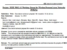
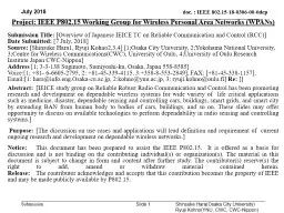
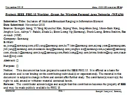
Submission Title A proposal for 802154u India band Date Submitted 11 January 2016 Source Benjamin A Rolfe Company Blind Creek Associates Address PO Box 798 Los Gatos CA 95031 ID: 675978

january rolfe bcaslide channel rolfe january channel bcaslide mhz 865 mode ben phy 2016 discussion band fsk 866 200

Share:

Link:

Embed:

Download Presentation from below link

Download Presentation The PPT/PDF document "January 2016 Slide 1 Project: IEEE P802..." is the property of its rightful owner. Permission is granted to download and print the materials on this web site for personal, non-commercial use only, and to display it on your personal computer provided you do not modify the materials and that you retain all copyright notices contained in the materials. By downloading content from our website, you accept the terms of this agreement.


Presentation Transcript

Slide1

January 2016

Slide 1

Project: IEEE P802.15 Working Group for Wireless Personal Area Networks (WPANs)Submission Title: A proposal for 802.15.4u (India band)Date Submitted: 11 January 2016Source: Benjamin A. Rolfe Company: Blind Creek AssociatesAddress: PO Box 798 Los Gatos CA 95031Voice: +1 408 332 0725, E-Mail: ben @ blindcreek.com Re: A proposal to meet the project scope and criteria stated in the Call for ProposalsAbstract: Presentation summarizing the technical requirements and proposed amendment to meet those requirements with minimal risk and complexity.Purpose: Satisfy the need for a standard PHY that can operate in the 865-867 MHz band. Notice: This document has been prepared to assist the IEEE P802.15. It is offered as a basis for discussion and is not binding on the contributing individual(s) or organization(s). The material in this document is subject to change in form and content after further study. The contributor(s) reserve(s) the right to add, amend or withdraw material contained herein.Release: The contributor acknowledges and accepts that this contribution becomes the property of IEEE and may be made publicly available by P802.15.

Ben Rolfe, BCASlide2

Purpose and objective

Meet the requirements of the approved project by adding the channel plan to support operation of

the currently defined SUN FSK PHY in the band indicated below using all other PHY characteristics (e.g. modulation parameters, PPDU format) that are identical to the SUN FSK PHY modes already defined.January 2016Slide 2Ben Rolfe, BCAIndia865-867Data Rate (kb/s)50100150*Modulation Index1.0

0.5

0.5

Channel Spacing (MHz)

200

200

200

* See Discussion slidesSlide3

Summary of Project Scope

PAR scope: This amendment defines a PHY layer enabling the use of the 865-867 MHz band in India. The supported data rate should be at least 40 kb/s per second and the typical Line of Sight (LOS) range should be on the order of 5 km using

omni directional antenna. Included are any channel access and/or timing changes in the MAC necessary to support this PHY layer.January 2016Ben Rolfe, BCASlide 3Slide4

Proposal Conforms to

Project Scope

Objective from PAR scopeMet by this proposalNotesDefine a PHY Layer enabling the use of the 865-867 MHz band in IndiaYESData Rate at least 40kb/s

YES

Minimum proposed

rate is 50 kb/s

Typical LOS range on the order of 5km

YES

Based on field performance of 802.15.4g deployments in other sub-GHz bands

Channel access and/or timing changes in the MAC necessary to support this PHY layer

YES

No channel access or timing changes are required to support the PHY in this proposal, as all PHY characteristics are identical to existing PHY defined in the standard.

January 2016

Ben Rolfe, BCA

Slide

4Slide5

Technical Details

See document 15-16-0032 for proposed amendment text.

January 2016Ben Rolfe, BCASlide 5Based on P802.15.4REVc-D02:Add row to table 10-170 defining bandAdd row to table 10-179 defining channel numbering Add row to table 20-245 specifying base symbol timingAdd row to table 20-250 to define modulation and codingSlide6

Technical Details

January 2016

Ben Rolfe, BCASlide 6Band designationFrequency band (MHz)866 MHz865-867Table 10-170:Table 20-245:Table 20-250:Frequency band (MHz)Symbol duration used for MAC and PHY timing parameters (μs)902–928

20

Frequency band (MHz)

Parameter

Operating mode #1

Operating mode #2

Operating mode #3

865-867

Data rate (kb/s)

50

100

150

Modulation

2-FSK

2-FSK

2-FSK

Modulation index

1.00.5

0.5

Channel spacing (kHz)

200

200

200Slide7

Advantages of this Proposal

Satisfies all the requirements stated in the project

authorizationSatisfies the needs identified in the CFPDoes not change anything that does need to be changedCan be implemented by existing equipmentMillions of 802.15.4 SUN FSK devices already deployedMany can add channel plan with firmware update in the fieldUses the stuff that’s widely used, proven to workEntire amendment will be 1 page of normative contentLow risk of introducing technical errorsLow risk of messing up stuff already in the standardMinimizes distractions High probability of getting the project finished on schedule January 2016Ben Rolfe, BCASlide 7Slide8

Why?

Because we want this:

January 2016Ben Rolfe, BCASlide 8Not this:Slide9

Discussion Topics

January 2016

Ben Rolfe, BCASlide 9150 kb/s 2-FSK in 200 kHz channel spacingChannelization- 9 channel vs 10 channel plansSlide10

Discussion on Op Mode #3

Concern:

Operating at 150ksps in a 200kHz channel with 802.15.4 SUN FSK transmit tolerances results in overlapping channelsJanuary 2016Ben Rolfe, BCASlide 10Slide11

Discussion on Op Mode #3: Is it possible?

January 2016

Ben Rolfe, BCASlide 11Simultaneous use of 200kHz channels looks possible, with some impact on the adjoining channels…when the signal is clean and frequency stability tight. This shows a typical implementation that meets the output spectral mask defined in the standard by large margins. -25dB

-30dB Slide12

Discussion on Op Mode #3: 802.15.4 SUN FSK Transmit Spectral Mask

January 2016

Ben Rolfe, BCASlide 12Transmit spectral mask: . M1 = 1.5 × R × (1 + h)M2 = 3 × R × (1 + h)h = 0.5 R = 150 kHzM1 = 337.5 kHz With 200 kHz channel spacing this means the -25dB step down is past the middle of the adjacent channels!Slide13

Discussion on Op Mode #3

January 2016

Ben Rolfe, BCASlide 13With the transmit mask specified in the standard: M1 = 1.5 × R × (1 + h)M2 = 3 × R × (1 + h)h = 0.5 R = 150 kHzA conforming transmitted signal could look like this…full power at the channel boundary!ChannelSlide14

Discussion on Op Mode #3: Mask compared to real-world example.

January 2016

Ben Rolfe, BCASlide 14Slide15

Discussion on Op Mode #3: Frequency Offset

January 2016

Ben Rolfe, BCASlide 15The frequency 41.175 kHz1. If we assume the worst case frequency offset we could have one device transmitting at 918.4412 MHz or 918.3588 MHz. This would move the 10dB point in the “tight” signal example into the adjacent channel, which is significant. This would most certainly cause interference, cause CCA to report “busy”, etc. . Now consider devices occupying adjoining channels each with the worst cast offset in opposite directions: The separation of center frequencies is 117.65 kHz 1. [802.15.4-2015 RevC Draft 02 20.5.3] Slide16

Discussion

on Op Mode #3: Frequency Offset

January 2016Ben Rolfe, BCASlide 16Slide17

Discussion on Op Mode #3:

Possible on Paper, Practical in air?

Options:Drop modeSimple and effectiveUse wider channel spacingAllowed by regulations?Specify tighter tolerances when using the bandRequires further analysis to map “possible” to “practical”Define it and expect implementers will figure it out in order to meet regulatory requirements and/or make useful stuff. Potential for a ‘compliant’ device to take out 3 channelsRegulations may be enough to force reasonable solution – but then why specify something we know isn’t allowed?January 2016Ben Rolfe, BCASlide 17Slide18

Alternate Channel Plans

January 2016

Ben Rolfe, BCASlide 18To guard or not to guard?Slide19

Discussion on Op Mode #3: Channel Centers

January 2016

Ben Rolfe, BCASlide 19Pro: 10 is more than 9Con: Channels 0 and 9 may not be usable Frequency band (MHz)ModulationChanSpacing (MHz)TotalNumChanChanCenterFreq0 (MHz)865-867SUN FSK operating mode #1, #2 0.210865.1Frequency band (MHz)

Modulation

ChanSpacing

(MHz)

TotalNumChan

ChanCenterFreq0 (MHz)

865-867

SUN FSK operating mode #1, #2

0.2

9

865.125

Chan#

0

1

2

3

4

56789MHz865.1

865.3

865.5

865.7

865.9

866.1

866.3

866.5

866.7

866.9

Chan#

0

1

2

3

4

5

6

7

8

MHz

865.125

865.325

865.525

865.725

865.925

866.125

866.325

866.525

866.725

Pro: Protection at the band edges

Con: 9 is less than 10Slide20

Thanks for your time

January 2016

Ben Rolfe, BCASlide 20

Related Contents

Next Show more