/
Non- contact Safety Non- contact Safety

Non- contact Safety - PowerPoint Presentation

calandra-battersby
calandra-battersby . @calandra-battersby
Follow
342 views
Uploaded On 2019-11-22

Non- contact Safety - PPT Presentation

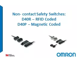
Non contact Safety Switches D40R RFID Coded D40P Magnetic Coded What is driving the need for the noncontact switches ISO 141192013 Safety of machinery Interlocking devices associated with guards Principles for design and selection ID: 766802

d40r d40p cable m12 d40p d40r m12 cable safety tamper food resistance series 2013 14119 iso 10m ip69k rfid

Share:

Link:

Embed:

Download Presentation from below link

Download Presentation The PPT/PDF document "Non- contact Safety" is the property of its rightful owner. Permission is granted to download and print the materials on this web site for personal, non-commercial use only, and to display it on your personal computer provided you do not modify the materials and that you retain all copyright notices contained in the materials. By downloading content from our website, you accept the terms of this agreement.


Presentation Transcript

Non- contact Safety Switches: D40R – RFID CodedD40P – Magnetic Coded

What is driving the need for the non-contact switches?ISO 14119:2013 Safety of machinery -- Interlocking devices associated with guards -- Principles for design and selection AbstractISO 14119:2013 specifies principles for the design and selection independent of the nature of the energy source of interlocking devices associated with guards. It covers the parts of guards which actuate interlocking devices. ISO 14119:2013 provides measures to minimize defeat of interlocking devices in a reasonably foreseeable manner. Simpler means of applying and conforming to the standard

Non-contact Safety Switches Application Requirements Measures against Defeating Interlocks D40Z/D40A CM MA MF MFS Gap in Offering Gap in Offering Low or Medium Level Coding High Level Coding

OverviewD40RCombines RFID coding technology with IP69K ingress protection and standard mounting sizes. Basic (single – teachable) and uniquely coded models are offered.Unique coding (32,000,000 possible code) provides “high” tamper resistance in accordance with the standard ISO 14119. D40P Coded magnet using Hall Effect technology with long life, trouble free solid state outputs. Multiple sizes and case materials to meet the requirements of food & beverage, packaging and factory automation markets. IP69K / stainless steel versions; special food industry version mounts from the back with no front recesses, all have smooth mirror-polished surfaces. Provides “low” tamper resistance in accordance with the standard ISO 14119.

Markets

Target Industries / ApplicationsTarget industry:Food & BeveragePackaging Automotive Target applications:Sanitary Packaging LinesMaterial Handling/PalletizingRobotic Welding CellsDirty EnvironmentsWet EnvironmentsPackaging Machines D40P D40R

Food & Beverage Filling Machine D40P IP69K Stainless steel hygienic or special food type models

Packaging Roll-fed Thermoforming Machine D40R Highly tamper resistant (unique code versions),

Automotive / Metal Processing Non-ferrous cutting machine applications D40R D40P

Update Existing ApplicationsSingle keyed door switch can be easily bypassed or fail due to damageNon-contact door switches can be added to existing applications to upgrade them to a higher performance level

Features

D40P versus D40R Comparison 12 D40P – Hall effect Coded Magnet Difficult to defeat without actuator Low Tamper Resistance per ISO14119 D40R-_B – RFID Unique Coding Impossible to defeat without actuator – 32 million codes High Tamper Resistance per ISO14119 GOOD BETTER BEST D40R-_B – RFID Basic Coding Possible to defeat with SPARE actuator but needs re-teachingLow Tamper Resistance per ISO14119

Clean In Place / Sanitized in Place (CIP/SIP) D40P Coded Magnet SwitchesIP69K RatingClean and Sanitize in Place + 105 C temperature rating Stainless Steel Housings with “Ra4 Mirror Polish” finish “Food” versions mount from back presenting smooth surfaceAlternate solutionPlastic models can work from through stainless steel Safe for use with Clean-in-Place or Sanitize-in-Place Applications

High Tamper Resistance High tamper resistance according to ISO 14119 Unique actuators with 32,000,000 different codes D40R-_U

● 15No special controller required! D40P D40R Connect to virtually any Safety monitoring device with 2 NC inputs

Connect up to 20 switches in series … Reduce the number of controllers required Individual Auxiliary Outputs Individual Operation indicators Door Closed Door Closed Door Closed Door Open <2mS Response Time NOTE: PLd/Cat.3 when switches are connected in series

Wiring Accessories End of Line Termination: Shorting Plug Connection Extension: Double-ended M12 Male to Female Cables Any D40R/D40P-_-M12 model Any D40R/D40P-_-M12 model Any D40R/D40P-_-M12 model T-Connector: Allows series connection of up to 20 sensors Simplify and quicken installation with fewer wiring errors NOTE: Auxiliary outputs are parallel connected; PLd/Cat.3 when switches are connected in series Up to 20 sensors in series

Safety and Electrical StandardsEN ISO 14119:2013 Safety of Machinery. Interlocking Devices Associated with Guards, Principles for Design and Selection EN ISO 13849-1:2008+AC:2009 Safety of Machinery, Part 1: General Principles for DesignEN 60497-5-3:2013 Low Voltage Switchgear and Control Gear – Part 5-3EN 62061:2005+AC:2010+A1:2013 Safety of Machinery, Functional Safety of Safety-related Electrical, Electronic and Programmable Electronic Control Systems ANSI/UL 508 Industrial Control Equipment CSA C22.2 No.14 Canadian Electrical Code Additional D40R Approvals: R&TTE Directive 1995/05/EC EN301 489-1:V1.9.2 (04/2012), EN301 489-1:V1.6.1 (03/2013), EN301 330-2:V1.5.1 (08/2010) Up to PLe, (up to PLd in series)

● 19 Models to Suit Most ApplicationsD40PPlastic (IP67) Stainless Steel (IP69K) Hygienic (IP69K ) Special Food Type (IP69K)D40RPlastic (IP69K / IP67)Diagnostic LED indicatorBasic or Unique CodingAll modelsLED operation indicator5m, 10m or M12 pigtail optionsCommon series connection accessories2NC/1NO Solid state, polarity free outputs D40P D40R

Sales Collateral

Web Pages

Printed Literature Combined 2-Page Flyer Separate Datasheets

Initially Stocked Items     D40P D40R-_B D40R-_U Accessories* Long (Plastic) 5M Cable D40P-LPC-21-05 D40R-LPB-21-05 D40R-LPU-21-05 ----- 10M Cable D40P-LPC-21-10 D40R-LPB-21-10 D40R-LPU-21-10 ----- M12 with 250mm Cable D40P-LPC-21-M12 D40R-LPB-21-M12 D40R-LPU-21-M12 ----- Small (Plastic) 5M Cable D40P-SPC-21-05 D40R-SPB-21-05 D40R-SPU-21-05 ----- 10M Cable D40P-SPC-21-10 D40R-SPB-21-10 D40R-SPU-21-10 ----- M12 with 250mm Cable D40P-SPC-21-M12 D40R-SPB-21-M12 D40R-SPU-21-M12 ----- Mini 5M Cable - Left D40P-MPC-21-05-L N/A N/A ----- 5M Cable - Right D40P-MPC-21-05-R N/A N/A ----- Barrel 5M Cable D40P-BPC-21-05 N/A N/A ----- Long SUS 5M Cable D40P-LMC-21-05 N/A N/A ----- Small SUS 5M Cable D40P-SMC-21-05 N/A N/A ----- M12 with 250mm Cable D40P-SMC-21-M12 N/A N/A ----- Small Hygienic 5M Cable D40P-SHC-21-05 N/A N/A ----- Mini Hygienic 5M Cable - Left D40P-MHC-21-05-L N/A N/A ----- 5M Cable - Right D40P-MHC-21-05-R N/A N/A ----- Small Special Food Type 5M Cable D40P-SFC-21-05 N/A N/A ----- Accessories* Single Ended 5M Cable ----- ----- ----- D40ML-CBL-M12-5M Single Ended 10M Cable ----- ----- ----- D40ML-CBL-M12-10M Double-Ended 2M Cable ----- ----- ----- D40P-8PMF-M12-02M Double-Ended 5M Cable ----- ----- ----- D40P-8PMF-M12-05M Double-Ended 10M Cable ----- ----- ----- D40P-8PMF-M12-10M Shorting Plug ----- ----- ----- D40P-8PSP-M12 T-Tap Cable ----- ----- ----- D40P-8PTC-M12 *Suitable for use with both D40P and D40R sensors.

Questions

Appendix: TechnologyReed Switch Hall Effect Transistor Hall Effect Sensors  are devices which are activated by an external magnetic field. We know that a magnetic field has two important characteristics flux density, (B) and polarity (North and South Poles). The output signal from a Hall effect sensor is the function of magnetic field density around the device. When the magnetic flux density around the sensor exceeds a certain pre-set threshold, the sensor detects it and generates an output voltage called the  Hall Voltage, V H . 

Appendix: TechnologyRFID How does an RFID system work?An RFID system consists of a tag, which is made up of a microchip with an antenna, and an interrogator or reader with an antenna. The reader sends out electromagnetic waves. The tag antenna is tuned to receive these waves. A passive RFID tag draws power from field created by the reader and uses it to power the microchip’s circuits. The chip then modulates the waves that the tag sends back to the reader and the reader converts the new waves into digital data.