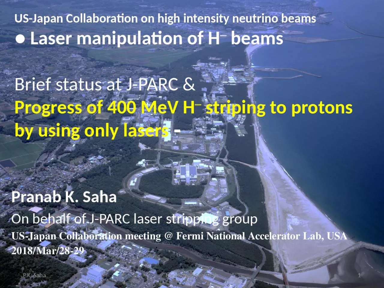
Laser manipulation of H beams Brief status at JPARC amp Progress of 400 MeV H striping to protons by using only lasers Pranab K Saha On behalf of JPARC laser stripping group ID: 917529
Download Presentation The PPT/PDF document "US-Japan Collaboration on high intensity..." is the property of its rightful owner. Permission is granted to download and print the materials on this web site for personal, non-commercial use only, and to display it on your personal computer provided you do not modify the materials and that you retain all copyright notices contained in the materials. By downloading content from our website, you accept the terms of this agreement.
Slide1
US-Japan Collaboration on high intensity neutrino beams
●
Laser manipulation of H
- beamsBrief status at J-PARC &Progress of 400 MeV H- striping to protons by using only lasers -
Pranab K. SahaOn behalf of J-PARC laser stripping groupUS-Japan Collaboration meeting @ Fermi National Accelerator Lab, USA2018/Mar/28-29
P.K. Saha
Meeting at Fermilab
1
Slide2Meeting at Fermilab2P.K. SahaLaser manipulation of H- beams--- status at J-PARCThree major activities:-- Proof-of-principle (POP) demonstration for 400 MeV H- stripping to protons by using only lasers.Goal to realize laser stripping H- charge exchange system.-- Developments of H- neutralization system by using laser for J-PARC TEF.R&D studies at 3 MeV H- now. To be tested for 400 MeV H- and put the system for operation.-- Multi-laser-wire diagnostic system for measuring H- beam profiles at J-PARC.R&D stage, Laser stripping chamber will be used.
Slide3Outline: 1. Brief introduction of J-PARC and the RCS 2. Motivation of H- laser stripping 3. Principle of H- stripping by only lasers 4. Experimental strategy, progress to date 5. Summary and outlookMeeting at Fermilab3P.K. Saha
Slide4Neutrino Beam Line to
Kamioka (NU)
Materials & Life Science Facility (MLF)
3 GeV Rapid Cycling Synchrotron (RCS)
Hadron Experimental Hall (HD)
400 MeV H
-
Linac
50 GeV Main Ring Synchrotron (MR) [30 GeV at present]
J-PARC
KEK & JAEA)
P.K. Saha
Meeting at Fermilab
4
Slide51. Introduction of J-PARC 3-GeV RCSP.K. SahaMeeting at Fermilab5Layout of J-PARC 3-GeV RCS● Multi-turn H- stripping injection.(stripping efficiency: 99.7% design)● Injection Energy: 400 MeV● Extraction Energy: 3 GeV● Repetition: 25 Hz● Beam power (design): 1MWSuccessfully demonstrated in the beam studies!Mid-term plan for beam power
Upgrade to 1.5 MW!Two big reasons: ① RCS beam sharing to the MLF and MR.When MR runs at 1s cycle (~2018), RCS beamsharing to MLF becomes: (25-4)/25 = 0.84RCS equivalent beam power to the MLFshould be 1.0/0.84 = 1.2 MW!② Also planning for a second neutron production target station at MLF.Stripper foil lifetime may be the most concerning issue!● Feasible scenario:Peak current: 50 60 mAInjection pulse: 0.5 0.6ms
Slide6MotivationP.K. SahaMeeting at Fermilab6An alternate H- stripping method other than using stripper foil. Laser stripping of H- holds the promise of eliminating limitation and issues involved of using stripper foil.Reasons:■ May be hard to maintain stable and longer foil lifetime for 1 MW routine operation at J-PARC RCS.■ Foil may not survive at 1.5 MW beam power.■ Foil scattering beam loss and the resulting high residual radiation at the injection area is already a serious concern for hardware maintenance even at lower beam power.★ Additional collimators had to installed at the downstream of stripper foil.
★ New design of the injection chicane magnets to install radiation shielding surrounding the foil are in progress.
Slide7Experience of stripper foil behaviors at the SNS and J-PARCP.K. SahaMeeting at Fermilab7ToPbeam(MW)
Beam sharing(%)e_painting(p mm mrad)Foil hit
MLF
1
84
200
10
MR
1
16
50
70
S.
Cousineau
(HB2014)
Normalized avg. foil hit: ~20 but
instantaneous foil heat for MR cycle is extremely high!
If the total charge limit on foil is 10000 C
Foil lifetime at 1 MW: 2 weeks at best!!
J-PARC: 0.3 MW operation
Avg. foil hit: 10
Foil hit at 1 MW operation (estimation)
Unstripped H
-
increased
twice more.
Waste beam dump
capacity: 4 KW
Slide8Energy deposition and foil temperature(Comparison between RCS and the SNS for 1 MW beam power)P.K. SahaMeeting at Fermilab8AcceleratorT [GeV]tinj[ms]
Foil thickness [mg/cm2]Avg. foil hitEnergy Depo.(dE) [J]Wpeak (DE/tinj)[Watts-peak]
J-PARC RCS
0.4
0.5
340
10
0.2598
276
SNS-AR
1
1
300
6
0.0712
71
W
peak
and foil temperature (T):
W
peak
∞
T
4
W
peak
(RCS) /
W
peak
(SNS) = 4
T (RCS) ≈ 1.4 x T (SNS)?
(Rep rate not taken into account)
If stripper foil limits SNS beam
power to 1.5 MW,
it is then may be 1 MW at
J-PARC RCS!!
Slide9Residual radiation at the RCS injection areaP.K. SahaMeeting at Fermilab9M. YoshimotoResidual radiation near the stripper foil is as high as 15 mSv/h on contact, 4 hours after 0.4 MW routine operation!
Slide10Review of our earlier study for laser assisted H- stripping at 400 MeV (same as SNS framework)P.K. SahaMeeting at Fermilab10Magnetic field issues:● In the practical application, the magnets should have larger radius.● For 400 MeV H-, hard to realize over 2 T magnetic field.● Circulating beam size after injection is quite large!
r ~5 cm!A. Aleksandrov, HB2014For SNS 1 GeV H-Magnetic field 1.2TInner radius: 0.15cmPeak power: 1 MWStripping eff.: 90%J-PARC RCS: 400 MeV injection for 1 MW.Beam distribution at the end of injection.( Simulation: TP: none, LP: full )
Slide11Principle of H- stripping by only lasersat J-PARCH-H0H0*p
e-e-
e
-
e
-
Excimer laser
l
= 193 nm
Step 1:
H
-
+
g
→
H
0
+ e
-
Step 2:
Excitation of H
0
H
0
+
g
→
H
0
* (n=3)
Step 3:
H
0*
+
g
→ p + e-Nd
: YAG Laserl=1064 nmNd: YAG Laserl=1064 nm63.3°90°90°Isao Yamane, Hiroyuki Harada, Saha Pranab and Shinichi KatoPASJ, Vol. 13, 2016, 1-11 (in Japanese)Doppler effect of the 400
MeV H-
beam:
b = 0.713,
g
= 1.426
l
=
l
0
(1 +
b
cos
a
)
g
Process
E
ph
(eV)
l
(nm)
a
(deg.)
l
0
(nm)
Laser
H
-
H
0
1.67
1064
90
743
Nd:YAG
H
0
H
0
*
12.1
193
63
102
Excimer (
ArF
)
H
0
*
p
1.67
1064
90
743
ND:YAG
D
E=12.1 eV
D
E =
hc
/
l
0
l
0
= 102 nm
11
P.K. Saha
Meeting at
Fermilab
Slide12SNS demonstrated 90% stripping for 1 GeV 10 ms H- pulseH-p
Laser pulse and peak power:Nd:YAG laser of 1064 nm 3rd harmonic conversion (355 nm)Synchronized to 402.5 MHz H- pulses.Pulse energy and width: 50mJ, 50ps Peak power: 1 MWSNS, Oak RidgeB >1TStripping efficiency: Achieved > 90%
Slide13Photodetachment, Photoionization cross sectionsand the corresponding laser power13743 nms = 4×10-17 cm2
13800nms= 1.8×10⁻¹⁷ cm2Eph = 1.67 eV @ 743 nmSaturation density Fs in PRFFs = (Eph/s) = 6.7×10⁻³ J/cm2
r(H-) = 1mm, t(H
-)=30 psecti(collision) = 10 psec, tl(laser) = 40 psec E(laser) = (
Fs/g)×(p
r
2
)×(
t
l
/
t
i
)
=
0.6
mJ
15 MW
L. M. BRANSCOMB, “Physics of the One-And-Two-Electron Atoms”,
Edited by F. Bopp and H.
Kleinpoppen
, North-Holland,
(1969)
E(laser) =
1.3
mJ
33 MW
Photodetachment
H
-
H
0Photoionization H0* pH- neutralization is well studied in many places:FNAL: Laser notcher systemJ-PARC TEF: R&D studies for 3 MeV H-.P.K. Saha
Slide14Lasers we have for the POP demonstrationP.K. SahaMeeting at Fermilab14Two Nd: YAG lasers available:Purpose: 1st (H- H0) and 3rd (H0* p) stripping1. Nd: YAG 1064 nm, 5-9 ns (FWHM), E= 0.2 ~0.6 J -- Detail study under progress with 0.2 J 2. J-PARC TEF facility has one more powerful YAG laserNd: YAG 1064 nm,
5-9 ns (FWHM), 1.6 JTest experiments done for 3 MeV H- neutralization. Excimer laser:ArF 193 nm excimer laser (by Mlase)Energy= 13 mJ, Pulse length = 5-10 ns (s) Bandwidth: ~4THz Ppeak > 1 MW can be reachedExcitation efficiency: 90% might be achieved.If we succeed pulse compression of the ArF laser, we can reach Ppeak >> 1 MW ArF 193 nm excimer laserManufacturer data 193 194…. Air N
2 purged
0.3 ×0.6 mm2
Slide15JFY 2017 progress highlightsP.K. SahaMeeting at Fermilab151. Preparation of POP (Proof-of-principle) demonstration of 400 MeV H- stripping to protons by using only lasers at J-PARC is under preparation. --- Vacuum chamber in the beam line is installed. --- R&D of the lasers are also in progress. --- Simulation, H- beam manipulations more details from now.2. For R&D of the lasers we have new collaboration with Kyoto Univ. and the Univ. of Electro-communications, Tokyo (in progress). ---(H. Harada leading)3. Dr. Timofey from SNS visited J-PARC for 2 weeks in March as an invited fellow.-- Worked with Saha to develop pyORBIT code for 400 MeV H0 excitation.-- Discussion on the J-PARC laser stripping strategy, H- beam manipulation, etc.Laser peak power for H0 excitationSpecially optimized H- beam1.3 MW for 90% excitation
Slide16Recent status and the strategy in detailP.K. SahaMeeting at Fermilab16We aim to demonstrate ~90% stripping efficiency for a single micro pulse.To do■ We should study about the expected laser power and effort to reduce the laser power.■ Experimental strategy and the measurement techniquesWe should use existing devices and monitors for the POP demonstration.● Extensive R&D studies of the lasers: H. Harada, P.K. Saha + other members..● H- beam manipulation, measurement principles…P.K. Saha, A. Miura, H. Harada + other members…
Slide17P.K. SahaMeeting at Fermilab17Experimental place, beamline The POP experiment will be performed at the end section of L-3BT (Linac to the 3-GeV Beam Transport)H-H-H0p
Slide18P.K. SahaMeeting at Fermilab18Experimental Setup and strategy ● We can simultaneously measure all three charge fractions in three separated beam lines in the downstream of IP.● A stripper foil will be installed near 90-deg dump to strip H0 to p for measuring it.For confirmation of H0 excitation, we can also measure emitted lights from H0 decay. Setup for the POP experiment(Nd: YAG laser can also be splitted inthe beginning for the 1st and 3rd steps)
Slide19POP experimental devices setupQM61~1.5mH- beamChamber for the POP chamber 19End section of Linac to 3-GeV Beam Transport
Slide20Vacuum chamber for POP experiment installedP.K. Saha20H- beamThe chamber is designed for multi purpose laser manipulation of the H- beam.● Laser stripping of 400 H- beam.● Multi-layer laser wire monitor.● Electron impact on H-/p for beam for stripping, monitoring, SC neutralization, etc.. Meeting at Fermilab
Slide21P.K. Saha21There are many windows on the chamber for multi-purpose uses.Vacuum chamber: close viewThe excimer laser window is made large to try for direct ionization of ground state H0l0 = 91.2 nm, l = 193nm,From l = l0(1 + bcosa)g a = 47oVariation range: 67o<a<45o Meeting at Fermilab
Slide22Laser power for 400 MeV H0 excitation (n=3) at J-PARC:-- Based on SNS experience V. Danilov, PRST-AB 6, 053501 (2003)Where, d is the ratio of unexcited and excited atoms. d
<<1 is expected.Ppeak = 1 MW for 90% efficiencyAt 400 MeV (b=0.713, g =1.4263), Naively, Ppeak ~1.7 MW is required 90% efficiency.To reduce the laser power, extensive manipulations of the H- beamwere done at the SNS:★ Shorter longitudinal beam size. sz = 30 ps Not an issue for our POP expt. ★ Dispersion derivative of the H- beam★ Minimization of the betatron angular spread★ Smaller vertical beam sizeLaser peak power, Ppeak for H0 excitation n=13 How much we can optimize these parameters?P.K. Saha22
Meeting at Fermilab
Slide23Reduction of laser power Let’s take the equation of laser beam angular spread (Yamane-san)
Required angular spread of the laser pulse: Introduce dispersion derivativeReduction of betatron angular spread (page 14)
0P.K. Saha
23=
Meeting at Fermilab
Slide24In order to eliminate transition frequency spread, due to the momentum spread dp/p0 in the H- beam, dispersion (D) tailoring method is utilized.= = -1.3 Due to the Doppler effect= l0 (1+bcosa)gb, g are Lorentz parametersa = a0 – x’, da = -x’For reference particle (dp/p0=0),a = a0 For off-momentum particle, x = D(dp/p0), x’ = D’(dp/p0)From dp/p0 = (1/
b2) dg/gda/dg = -D’/b2gThe dispersion relation becomes,g1g2g3gnaH0H0*
Uniform laser beam
● Hydrogen atom with different energies have the same laser light frequency in their rest frame.● Laser light does not have to have a divergence. Gain on the laser peak power.Dispersion derivative
of the H- beamg0P.K. Saha
24
Meeting at Fermilab
Slide25Optimization of betatron angular spreadXX’Transverse beam emittance:e = gx2 + 2axx’ + bx’2g = (1+a2)/btan(2f) = 2a/(g-b)a, b, g, e are twiss parametersAngular spread is controlled by optimizing a to zero and also with large b.
a = 0XX’
{
fa = 0, b enlargeAs for the vertical size of the H
- beam, a smaller size is required to gain on the beam density. At SNS, sv = 0.15 mm achieved.P.K. Saha
25
Meeting at
Fermilab
Slide26Trial optimization of the H- beam~ Typical1st trail of optimized for POP experimentFurther more studies neededIPTransverse beam optimization at the IPD’ = -0.13 Efforts are ongoingIPP.K. SahaMeeting at
Fermilab26
Slide27Measurement Strategy for POP demonstration, expected signalP.K. SahaMeeting at Fermilab27
20nsExcimer laser pulseTypical 324 MHz BPM electrode signal.The H- beam signal will be reduced in the laser pulse overlapping region.The protons go to the 100 deg. dump.H- pulse3ns
. . .
3.08ns
Micro pulse (324 MHz)
814ns
456ns
. . .
Intermediate pulse (1.2285 MHz)
(Structure @ injecting into the RCS)
0.5ms
40ms
. . .
Cycle (25 Hz)
RCS
Macro pulse
We concentrat
e only on a single micro pulse.
Use
stripline
BPM signal.
Slide28How to cover 0.5 ms (~105 micro pulses)for practical application?28toroidal mirror
toroidal mirrorplane mirrorSplitter mirrorLensseed laser100mJ, 100psec, 25Hzwaistwaist(IP)waist
(
transmission
:
~1%
)
amplifier
amplifier
laser output
monitor
H
-
beam
One candidate: Laser storage ring, originally
proposed
by Isao Yamane.
We plan for detail R&D studies but many issues
to realize full specifications, especially for
the excimer laser.
Amplification, laser life time …
Alternative ideas should come.
H. Harada
Slide29Measurement method of stripping efficiency of a single micro pulseChecked by inserting L-3BT scrapper at present(Charge-exchange type transverse beam halo scrapper. Stripped protons goto the 100-deg. Beam dump)P.K. Saha29Meeting at Fermilab
Slide30Measurement techniques: Experimental resultsFFTStripping efficiency of single medium pulse can easily be obtained by using FFT analysis.However, we have to obtain stripping efficiency of a single micro pulse of 324 MHz. Analysis of individual micro pulseP.K. Saha30Meeting at Fermilab
Slide31Analysis of individual micro pulse● New effort to measure micro pulse stripping efficiency.● Can be utilized also for micro pulse stability.100-deg. dump (p)L-3BT line (H-)Fraction p : pink to redFraction H- black to blueP.K. Saha31Meeting at Fermilab
Slide32P.K. Saha32● The detail studies of ND:YAG laser are in good progress. At present detail of laser stability, pulse shape up to with 200 mJ are being studied.★ The ArF excimer laser study just started.★ We will work for pulse shortening of the lasers.★ Placing lasers at the acceleration tunnel is big issue!Laser stripping of 400 MeV H- beam--- Scheduled step by stepH- neutralization study first.Meeting at Fermilab
Slide33P.K. SahaMeeting at Fermilab33The preparation for POP demonstration of 400 MeV H- stripping by using only lasers at J-PARC is in progress.The experiment will be carried out in steps. First trial of complete set of experiment planned within JFY 2018.Laser and H- beam manipulations more studies needed.Measurement technique for even a single micro pulse established.POP final goal: 90% stripping efficiency for a single micro pulse.Next step, not straightforward to cover ~105 micro pulses.Candidates: Laser storage ring synchronized with 324 MHz H- micro pulse.Many issues for realistic implementation with full specifications.Other ideas have to come.Summary
Slide34Collaboration outlookP.K. SahaMeeting at Fermilab34■ Laser interaction of the H- beam for utilization in stripping, chopping, beam diagnostic and other manipulations are an important subject for the present and next-generation high-intensity proton accelerators.■ Non-destructive and highly required not only for the existing high intensity machines but also to realize multi-MW beam power.The collaboration aims atDeveloping a framework for an effective laser manipulation of the H- beam Achieve maximum efficiency with a minimum laser power.Explore for multi-dimensional application.. . . . . . . . . . . .