/
2.1GHz cavity without cell-to-cell coupling slots – 1.875 2.1GHz cavity without cell-to-cell coupling slots – 1.875

2.1GHz cavity without cell-to-cell coupling slots – 1.875 - PowerPoint Presentation

celsa-spraggs
celsa-spraggs . @celsa-spraggs
Follow
445 views
Uploaded On 2015-11-04

2.1GHz cavity without cell-to-cell coupling slots – 1.875 - PPT Presentation

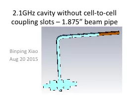
Binping Xiao Aug 20 2015 Cavity overview No coupling slots between cells Beam pipe aperture cell to cell amp end cell 1875 Dimensions cavity radius FPC slot height nose cones etc ID: 183018

11072 cell cavity ghz cell 11072 ghz cavity ohm beta 066 power mode radius fpc 06120 pipe beam 875

Share:

Link:

Embed:

Download Presentation from below link

Download Presentation The PPT/PDF document "2.1GHz cavity without cell-to-cell coupl..." is the property of its rightful owner. Permission is granted to download and print the materials on this web site for personal, non-commercial use only, and to display it on your personal computer provided you do not modify the materials and that you retain all copyright notices contained in the materials. By downloading content from our website, you accept the terms of this agreement.


Presentation Transcript

Slide1

2.1GHz cavity without cell-to-cell coupling slots – 1.875” beam pipe

Binping XiaoAug 20 2015Slide2

Cavity overview

No coupling slots between cells.

Beam pipe aperture: cell

to

cell & end cell 1.875”

Dimensions (cavity radius, FPC slot height, nose cones etc) are fine tuned.

A = 1.875”

ASlide3

Center cell

(beta=1)

(beta=1)

h [mm]

Rd [mm]

f [GHz]

Rsh [ohm]

R/Q [ohm]

Q

E-bound f [GHz]

fh-fe[MHz]

1

57.2542.11072.436E+06115.07621168.32.0499460.76256.73322.11072.460E+06118.514207592.0565554.152.556.44552.11072.466E+06120.17520520.12.0597150.99356.14332.11072.462E+06121.70320233.12.0627347.973.555.82782.11072.458E+06123.185199542.0656245.08455.50032.11072.446E+06124.54519642.22.0683842.32554.8152.11072.411E+06126.93618993.22.073537.2Slide4

End cell

aperture:

23.8125

radius in mm

h

2.5

mm

he

0

mm

∆L [mm]

10

(beta=1)(beta=1)r7 [mm]Rd [mm]f [GHz]Rsh [ohm]R/Q [ohm]Q256.24592.11072.715E+06120.83722467.93.556.29812.11072.702E+06120.00922516.3556.35792.110682.686E+06119.07622561.1756.44442.11072.662E+06117.71322613.4r7 blendingSlide5

3-cell

Center cell h = 2.5 mm, cell radius: 55.98 mmEnd cell h = 0 mm with 2 mm blending, cell radius: 54.26 mm

Fundamental mode: 2.11035 GHz, 6.69 M

Ω shunt impedance, power on cavity 9349.1 W.Modes separation: 2.0812 GHz

π/3 mode (+++), 2.0990 GHz 2π/3 mode

(+0-), 2.1105 GHz π mode (+-+).Slide6

Tuner

Lt [mm]

f [GHz]

R/Q [ohm]

Q

Qext

Qtuner

Rsh [Mohm]

QL

Pcavity [W]

Ptuner [W]

0

2.11035314.108521283219892.25E+066.685171210815.19349.188.3-62.10926312.285521516254998.59E+066.719134811669.49301.823.3-32.10964313.30921457240744.37E+066.722671211345.19296.945.732.11151315.091520982191541.21E+066.611249910013.29453.6164.062.11326314.019520511162157.16E+056.4408549055.99703.7277.9Slide7

RF loss

1

2

5

6

7

9

8

11

10

12

13

14,15

17

16

3

4

6

5

14

15

R/Q [ohm]

314.0455

Voltage [V]

250000

Material

Q

Power [W]

standingwave power [W]

1

2.35E+06

84.522105

2

5.00E+07

3.9829437

15.93177

3

4.83E+04

4119.3001

4

8.81E+04

2258.0529

5

3.08E+05

645.81953

6

1.61E+06

123.62762

7

1.52E+07

13.094003

52.37601

8

6.90E+07

2.8847879

11.53915

9

6.89E+07

2.8897306

11.55892

10

5.69E+07

3.4989319

13.99573

11

6.88E+07

2.890654

11.56262

12

6.99E+07

2.8479643

11.39186

13

1.08E+05

1848.9014

14

1.73E+09

0.1151645

0.460658

15

3.61E+08

0.55068

2.20272

16

5.46E+07

3.6439093

14.57564

17

1.55E+08

1.2825659

5.130264

total power

9117.905Slide8

And more

Alumina window RF loss: 5 Watt (1.25 Watt for travelling wave) with 250 kV.Fixed tuner 3/8” dia

, 5mm insertion, frequency increases 0.32

MHz.To compensate the possible Q-degradation brought by surface roughness or brazing. We choose

FPC stub 50mm away from the bottom of the flat area on the "V" waveguide, assuming the cavity is 1cm in thickness, we can use 2.75" flange with 1.625" clearance, and 1.5" bolt with 1"

dia thread and 10mm insertion.

FPC stub position [mm]Qext

QFPCtuner

No

21989

na

50

142942.71E+08Slide9

Summary

For

the 2.1 GHz warm RF system:

3-cell cylindrical cavity with nose cones and

without

coupling slots is designed, and is optimized on shunt impedance. A vacuum pump will be attached to the cavity using a Tee on one of the beam

pipe.Cavity

is fine tuned for field flatness.Cavity

performance at different tuners’ penetrations is evaluated.

To do list:

Error analysis, HOM modes up to 5 GHz, Pickup coupler.