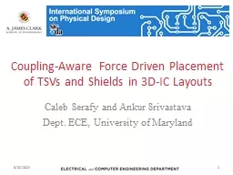
Caleb Serafy and Ankur Srivastava Dept ECE University of Maryland 3312014 1 3D Integration Vertically stack chips and integrate layers with vertical interconnects Through Silicon Vias ID: 400673
Download Presentation The PPT/PDF document "Coupling-Aware Force Driven Placement of..." is the property of its rightful owner. Permission is granted to download and print the materials on this web site for personal, non-commercial use only, and to display it on your personal computer provided you do not modify the materials and that you retain all copyright notices contained in the materials. By downloading content from our website, you accept the terms of this agreement.
Slide1
Coupling-Aware Force Driven Placement of TSVs and Shields in 3D-IC Layouts
Caleb Serafy and Ankur SrivastavaDept. ECE, University of Maryland
3/31/2014
1Slide2
3D Integration
Vertically stack chips and integrate layers with vertical interconnectsThrough Silicon Vias (TSVs)
Advantages:Smaller footprint area
Shorter global wirelengthsHeterogeneous IntegrationDisadvantages:
TSV-TSV coupling
TSV reliability
Increased power densityTrapped heat effect
3/31/2014
2Slide3
TSV-TSV Coupling
TSVs have large capacitance to substrateSubstrate is
conductive: low noise attenuationCoupling between TSVs must be minimized in order to maximize switching speed
SOLUTIONS: TSV spacing and TSV shielding
3/31/2014
3Slide4
TSV spacing
Spacing between TSVs can reduce couplingBut requires large distanceShield insertion can reduce coupling when spacing is small
3/31/2014
4Slide5
TSV spacing
Spacing between TSVs can reduce coupling
But requires large distance
Shield insertion can reduce coupling when spacing is small
3/31/2014
5
d
=12Slide6
TSV Shielding
3/31/20146
Shielding
: place a grounded conductor between two wires
EM waves cannot pass through shield, reducing coupling between wires
Guard
ring
is less effective with TSVs
TSVs require shielding
throughout the
thickness
of the silicon substrate
use GND TSV as shield
Optimal shield placement requires
chip-scale
coupling models
Analog
TransistorSlide7
Previous Work
Geometric model of couplingCircuit model of coupling too complex for chip-scale optimization
Developed model of S-parameter based on relative TSV positionsUsed curve fitting on HFSS simulation data
Shield insertion algorithmBased on fixed signal TSV locations, place shield TSVs to minimize coupling
Solved using MCF problem formulation
Avenue for improvement
Shield insertion cannot mitigate coupling if
spacingis too smallDetermine signal and shield positions simultaneously
3/31/2014
7[Serafy et. al GLSVLSI’13]Slide8
Force-Driven Placement (FDP)
Input:
Fixed transistor placement
Output:
Placement for signal and shield TSVs
Objective
: place signal and shield TSVsMinimize some cost function
Force: derivative of cost function
Solution: find total force F=0Iteratively solve for F=0 and then update forces based on new placement
3/31/20148Slide9
Forces
Wirelength (WL) Force: pulls objects towards position with optimal wirelengthOverlap Force: repels objects from one another when they
overlapCoupling Force: repels each signal TSV from its
most highly coupled neighborCoupling evaluated using our geometric model
Shielding Force
: Pulls shield TSVs towards the signal TSVs it is assigned to
3/31/2014
9Slide10
Proposed Algorithm
Assumption: Transistor cells are already placed, limiting the possible locations of TSVs (whitespace)Step 0: assign each signal TSV to a whitespace region
Step 1: perform coupling aware placement until equilibriumStep 2: insert shields using our shield insertion method
Step 3: repeat coupling aware placement until equilibrium
3/31/2014
10Slide11
Proposed Algorithm
Assumption: Transistor cells are already placed, limiting the possible locations of TSVs (whitespace)Step 0: assign each signal TSV
to a whitespace regionStep 1: perform coupling aware placement until equilibriumStep 2: insert shields using our shield insertion method
Step 3: repeat coupling aware placement until equilibrium
3/31/2014
11
Coupling Force Repels TSVs
Shield Reduces Coupling Force
WL force attracts TSVs back togetherSlide12
Initial Placement
Each signal TSV must be assigned to a whitespace region
Once assigned TSVs
cannot change regions
Objective:
Minimize
wirelength
Constrain #TSV assigned to each region
3/31/2014
12Slide13
Coupling Aware Placement
Without
With
Shield Insertion
Without
Traditional
CA
With
SI
CA+SI
Simulation Setup
Four Cases
Traditional Placement: WL and overlap force only
Placement with
coupling
force (CA)
Placement with shield insertion (SI)
CA+SI
3/31/2014
13Slide14
Experimental Results
3/31/2014
14
CA+SI required less shields than SI alone
Improvement due to CA+SI is
greater than the sum
of CA and SI alone
Change in total WL is an
order of magnitude smaller
than improvement to couplingSlide15
Illustrative Example
3/31/201415
Without Shields
With Shields
Coupling Unaware
Coupling Aware
CA+SI
CA
SI
TraditionalSlide16
Future Work
We have shown that signal and shield TSV placement must be done simultaneouslyAlso, coupling aware placement and shield insertion are complementary techniques
This approach should be integrated with transistor placementLarger solution space
No assumptions about TSV and transistor placementOptimize area
Instead of adding a fixed amount of whitespace for TSVs during transistor placement
3/31/2014
16Slide17
Questions?
3/31/2014
17Slide18
Backup Slides
3/31/2014
18Slide19
Simulating Coupling
S-parameter (S): ratio of energy
inserted into one TSV to energy emitted by another
Insertion loss, i.e. coupling ratioHFSS: Commercial FEM simulator of Maxwell’s equations
HFSS data is used as
golden data
to construct model
3/31/2014
19
Our model is for specific physical dimensions. The modeling approach can be reapplied for different dimensions.Slide20
Modeling Approach
In HFSS:Model two signal TSVsSweep distance
d between them
Add a shieldSweep d
and shield distance
y
x value does not change results
Add a second shield
Sweep y1
and y2Fit S(d,y1,y2
)
to HFSS data using curve fitting
3/31/2014
20Slide21
Modeling Approach
In HFSS:Model two signal TSVs
Sweep distance d between them
Add a shieldSweep d and shield distance y
x
value does not change results
Add a second shield
Sweep y
1 and y
2Fit S(d,y1,y2
)
to HFSS data using curve fitting
3/31/2014
21Slide22
Modeling Approach
In HFSS:Model two signal TSVsSweep distance
d between themAdd a shield
Sweep d and shield distance yx
value does not change results
Add a second shield
Sweep (
x1,y
1) and (x2
,y2)Fit S(d,x1,y
1
,x
2
,y
2
)
to HFSS data using curve fitting
3/31/2014
22Slide23
Modeling Approach
In HFSS:Model two signal TSVsSweep distance
d between themAdd a shield
Sweep d and shield distance yx
value does not change results
Add a second shield
Sweep (
x1,y
1) and (x2
,y2)Fit S(d,x1,y
1
,x
2
,y
2
)
to HFSS data using curve fitting
3/31/2014
23Slide24
Modeling Approach
In HFSS:Model two signal TSVsSweep distance
d between themAdd a shield
Sweep d and shield distance yx
value does not change results
Add a second shield
Sweep (
x1,y
1) and (x2
,y2)Fit S(d,x1,y1,x2,y
2
)
to HFSS data using curve fitting
3/31/2014
24Slide25
Extension and Validation
Double shield model:
Add results from single shield model:
S(d,y
1
)
+
S(d,y2)
Superposition is not an accurate modelSubtract overlap M(x
1,y1,x2,y2)Extension to n shields:Add results from single shield models:
S(d,y
1
)
+…+
S(
d,y
n
)Subtract overlap M(xi,yi,xj,y
j
)
for each pair of shields
Assumes higher order overlap is negligible
3/31/2014
25
Create random distributions of 3 and 4 shields
Compare HFSS results to model results
Average Error:
S3: 3.7 % S4: 9.4 %
S3: 1.6 dB S4: 4.6 dBSlide26
Coupling Model
3/31/2014
26Slide27
Poor Solution
Good Solution
Shield Insertion Algorithm
For each signal TSV pair we identify the region where a shield could improve the coupling of that pair
Assign a shield to each TSV pair using MCF problem formulation
Objective
: provide shielding for each TSV pair while
using least number of shields
Take advantage of region overlap
3/31/2014
27
[Serafy et. al GLSVLSI’13]Slide28
MCF Shield Insertion Algorithm
Each pair of signal TSVs defines a region
A set of positions that are
good candidates for shielding that pair
MCF problem
: assigns a shield to each TSV pair
Objective
: Maximize ratio of shielding added to shielding required (shielding ratio) for each TSV pair while using least number of shields
3/31/2014
28
From Serafy et. al GLSVLSI’13Slide29
MCF Problem Formulation
Region node for each TSV pair
Point node for each whitespace grid point
Point cost proportional to
total shielding ratio
True cost
of
each shield is
independent of amount of flow carried3/31/2014
29u = capacityc = cost
Heuristic
:
After each iteration scale cost by number of units of flow carried in previous iteration
From Serafy et. al GLSVLSI’13Slide30
Placement Forces
3/31/2014
30
A
: all signal TSVs assigned to this shield
F
KOZ
is the overlap force
Prevents a TSV from getting within the KOZ area of a transistor or another TSV
F
WL
is the wirelength force
Pushes each TSV towards its respective
netbox
TSVs inside the
netbox
have minimal WL and F
WL
= 0
F
C
is a new force which captures the coupling between two TSVs
Coupling force is proportional to the coupling between two TSVs
Each TSV has a coupling force from all other TSVs, but
only the strongest coupling force
is used to determine movement on each iteration
F
Shielding
pushes shield TSVs towards each signal TSV they are assigned toSlide31
Why max(Fc)
3/31/2014
31
Don’t let many loosely coupled TSVs overpower strongly coupled TSVSlide32
Raw Data
Traditional
CA
SI
CA+SI
B1
-25.0
-25.3
-25.2
-26.2B2
-25.3
-25.5
-26.1
-26.5
B3
-25.3
-25.3
-26.1
-26.4
B4
-25.3
-25.6
-25.2
-26.5
B5
-25.3
-25.3
-26.3
-26.4
B6
-25.3
-26.3
-26.1
-26.4
B7
-25.3
-25.7
-25.4
-26.4
B8
-25.2
-25.3
-26.1
-26.4
AVG
-25.3
-25.6
-25.8
-26.4
3/31/2014
32Slide33
Improvement (dB)
CA
SI
CA+SI
B1
-0.3
-0.1
-1.1
B2
-0.2-0.8
-1.2
B3
0.0
-0.7
-1.1
B4
-0.3
0.1
-1.2
B5
0.0
-0.9
-1.0
B6
-0.9
-0.7
-1.0
B7
-0.4
0.0
-1.0
B8
-0.1
-0.9
-1.2
AVG
-0.3
-0.5
-1.1
3/31/2014
33