/
An Improved Multiband Trap Dipole Antenna You need thi An Improved Multiband Trap Dipole Antenna You need thi

An Improved Multiband Trap Dipole Antenna You need thi - PDF document

celsa-spraggs
celsa-spraggs . @celsa-spraggs
Follow
436 views
Uploaded On 2015-05-30

An Improved Multiband Trap Dipole Antenna You need thi - PPT Presentation

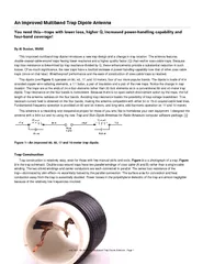
The antenna features doublecoaxialcablewound traps having lower reactance and a higher quality factor Q than earlier coaxcable traps Because trap loss resistance is determined by trap reactance divided by Q these enhancements provide a substantial r ID: 77398

The antenna features doublecoaxialcablewound

Share:

Link:

Embed:

Download Presentation from below link

Download Pdf The PPT/PDF document "An Improved Multiband Trap Dipole Antenn..." is the property of its rightful owner. Permission is granted to download and print the materials on this web site for personal, non-commercial use only, and to display it on your personal computer provided you do not modify the materials and that you retain all copyright notices contained in the materials. By downloading content from our website, you accept the terms of this agreement.


Presentation Transcript

Figure 2—Close-up of a completed trap. Figure 3—Double-coax trap schematic.The SWR performance of the antenna at my location, using a 50 to 75- transformer and a 75- feed line, is shown in Figure . The antenna is installed as an inverted with a 40-foot apex height. Notice the very good performance on 40 meters, where the SWR is less than 2 across the entire band. The antenna favors the low end of 10 meters, where most of the activity seems to be concentrated. On 17 meters, the SWR is close to 3 across the band, requiring an antenna tuner to keep the rig happy. The 2:1 SWR bandwidth on 80 meters is 75 kHz, centered on 3.79 MHz. A good antenna tuner can extend the operating bandwidth on 80 meters well into the CW portion of the band or into the General class phone portion. July QST: An Improved Multiband Trap Dipole Antenna - Page 2 ARRL1996QST/QEX/NCJCDCiht(C)1997bThAiRdiRlLI Figure 4—SWR plot of the improved trap dipole.I measured the Q of these traps at two widely separated low frequencies and extrapolated the results to the higher operating frequencies. This two-frequency extrapolation method solves an otherwise impossible problem of directly measuring the Q of are shown in Figure 5, where the Q of an RG-59 double-coax trap is compared with the Q of a common RG-59 coax trap. The Q of RG-59 over RG-58 is also demonstrated. All traps are tuned to a nominal 5.16 MHz and are of the optimum Q and length/diameter ratio. As you can see, the double-coax RG-59 configuration has a Q about 18% higher than the common singly wound coax configuration. Figure 5—Trap quality factor, Q, versus frequency.I calculated the trap losses for the bands covered using Roy (W7EL) Lewallen’s program. The results are shown in ARRL1996QST/QEX/NCJCDCiht(C)1997bThAiRdiRlLI Table 1. The antenna was assumed to be horizontally mounted, 40 feet above real ground and using the legal power-output limit of 80 meters, however, the antenna’s low height and its shortened length reduce the antenna input resistance to 51.8 , making trap traps is 2984 V, below the 3400-V rating of the cable.Table 1 — Trap Loss SummaryBand (meters)Freq (MHz)Radiation Efficiency (%)Trap Loss (dB)Trap Power Dissipation (W)80 3.8 68.21.66119.440 7.15 99.20.04 3.11718.1 99.90.001 0.041028.5 99.90.000 0.01My operating experience indicates that common coaxial-cable traps can dissipate 35 W or more without failure. Therefore, I far, I’ve operated this antenna only at the 600-W PEP output level of my Yaesu FL-7000 amplifier. (During subsequent ARRL Lab tests, these traps successfully handled a two-tone 1500-W PEP signal for 10 minutes with no signs of stress.—Ed.) If any amateur has a theoretical basis for calculation of trap power-dissipation capability, please let me know about it. Details of the trap construction and its connections to the antenna segments are shown in Figures 6 and . Before commencing construction, study the trap details in these figures as well as Figures 2 and . The trap resonant frequency is 5.16 MHz. Trap resonant-frequency tolerance is 50 kHz, permitting selection of a resonant frequency anywhere between 5.11 and 5.21 MHz. The band most sensitive to trap-frequency error is 80 meters, where a trap- frequency error of 50 kHz causes an antenna resonant-frequency error of 30 kHz of the same sign. Thus, if you have a General class ticket and want to be above 3.85 MHz on General class ticket holders may want to shorten the trap windings by an eighth of a double-turn to set the 80-meter antenna frequency above 3.85 MHz. In that case, increase the trap frequency to about 5.35 MHz. The trap frequencies should be checked resonant frequency have much smaller effects on the 40, 17, and 10-meter bands than on the 80-meter band.Making the Traps Describing how to make the traps is more difficult than making them! See Figures 6 and . Each trap consists of 6.88 doubleturns of seven-foot lengths of RG-59 (Belden 8241) coaxial cable (A and B) wound on a PVC form. [2 ] Each form is a 5.33-inch length of 3.5-inch-OD schedule-40 PVC pipe (three-inch PVC pipe). Confirm the 3.5-inch OD of the PVC because trap frequency is sensitive to form diameter. Drill two 0.25-inch-diameter holes at the windings’ start and end. See Figure 6. The center of the full seven turns. Therefore, the ending-turn holes are drilled of the circumference (1.375 inches) shy of seven full turns. The winding A lags 1.375 inches along the circumference behind the start winding hole for winding A.0.242-inch OD makes for a snug fit in the 0.25-inch-diameter holes.The seven-foot cable lengths leave four inches at each winding end to make the trap pigtails that extend inside the PVC form. windings. Clamp the far end of the windings in a vise to maintain firm and equal tension on the two cables as you wind them ARRL1996QST/QEX/NCJCDCiht(C)1997bThAiRdiRlLI tension on the cables, use your fingers and needle-nose pliers to push and pull the cables into the inside of the form.Using a sharp utility knife, strip away the last three inches of polyvinyl cover from the pigtails. Avoid cutting the shield braid.three-inch pigtail has now become two smaller pigtails—a shield pigtail and a center-conductor pigtail—each somewhat less than three inches long. Remove about two inches of the dielectric to expose the inner conductor. Convert all four ends of the cable windings into similar pigtail pairs.The center conductors at the start of the winding connect together, forming the trap input terminals for attachment to the 24.4-foot antenna wire. You may prefer to use crimp connectors rather than solder connections. Access to the inside of the traps—where the connections must be made—is somewhat awkward. The center conductors at the far end are fed back through the interior of the form, where they are connected to the shield braid at the start of the windings The far-end shield braids connect together to form the output terminal of the trap for attachment to the 17.4-foot antenna segment. It’s important to avoid reversing the input and output terminals of the traps! Reversal detunes the antenna a small amount by misplacing about 4 pF of stray capacitance of the trap shield braid. Build the second trap identical to the first. Figure 6—Hole positioning for the trap coil form. Figure 7—Cross-sectional view of a double-coax trap.SummaryUse a high-quality 1:1 balun for the antenna’s center support and feed terminals. The 24.4-foot antenna segments attach to the ARRL1996QST/QEX/NCJCDCiht(C)1997bThAiRdiRlLI balun’s output terminals. Attach the trap-input pigtails to the far end of the 24.4-foot segments. Check the 24.4-foot segment the 17.4-foot antenna segments. Check the 17.4-foot-segment lengths. Terminate the far ends of these segments in good-quality loose, allowing considerable antenna sag. Install the antenna as high as possible—at least 35 feet above the ground at the center—and with the ends at least 15 feet high. Feed the antenna with either 50 or 75- coaxial cable, the higher value being preferred to lower the feed-line SWR on 17 and 10 meters.That done, go and have some fun!Al Buxton, W8NX, can be reached at 2225 Woodpark Rd, Akron, OH 44333. Al has been a radio amateur since he was first licensed as W7GLC in 1937. A registered professional engineer, Al holds BSEE and MSEE degrees from Tulane University. His career spans industry and academia: 26 years in the defense industry with Goodyear Aerospace, six years with Tulane University “Trap and Stub Dipole Antennas for Radio Amateurs” is the culmination of eight years of developmental studies confirmed by experimentation, testing and development.Notes”Trap and Stub Dipole Antennas for Radio Amateurs” is available from Al Buxton, W8NX, PO Box 174, Columbus, Ohio 43216-0174. Price: $34.95 plus $5 shipping and handling. Many multiband wire or tubing antennas of your own choosing, employing both trap and/or short stub technology can be designed with this software. Make sure the coax you use has a polyethelene (not foam) dielectric. A foam dielectric allows the center conductor to migrate. ARRL1996QST/QEX/NCJCDCiht(C)1997bThAiRdiRlLI An Improved Multiband Trap Dipole Antenna You need this—traps with lower loss, higher Q, increased power-handling capability and four-band coverage!By Al Buxton, W8NXThis improved multiband trap dipole introduces a new trap design and a change in trap location. The antenna features ] Figure 1—An improved 80, 40, 17 and 10-meter trap dipole.Trap ConstructionTrap construction is relatively easy, even for those with few manual sk July QST: An Improved Multiband Trap Dipole Antenna - Page 1 ARRL1996QST/QEX/NCJCDCiht(C)1997bThAiRdiRlLI