/
Lifter  Step-by-step assembly instructions Lifter  Step-by-step assembly instructions

Lifter Step-by-step assembly instructions - PowerPoint Presentation

celsa-spraggs
celsa-spraggs . @celsa-spraggs
Follow
375 views
Uploaded On 2018-03-12

Lifter Step-by-step assembly instructions - PPT Presentation

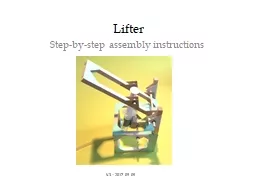
V3 2017 09 05 Contents of the Lifter Kit Wooden pieces 1 cm crosssection 8 X 91 cm 6 X 8 cm 4 X 2025 cm 2 X 825 cm 2 X 38 cm 3 X 25 cm Green corner gussets 2 cards Syringes 20cc 2 1 has a hole in the plunger ID: 648778

2017 axle syringe glue axle 2017 glue syringe pieces holder holders place uprights shown cube plunger green platform align

Share:

Link:

Embed:

Download Presentation from below link

Download Presentation The PPT/PDF document "Lifter Step-by-step assembly instructio..." is the property of its rightful owner. Permission is granted to download and print the materials on this web site for personal, non-commercial use only, and to display it on your personal computer provided you do not modify the materials and that you retain all copyright notices contained in the materials. By downloading content from our website, you accept the terms of this agreement.


Presentation Transcript

Slide1

Lifter

Step-by-step assembly instructions

V.3 – 2017 09 05Slide2

Contents of the Lifter Kit

Wooden pieces (1 cm cross-section): 8 X 9.1 cm; 6 X 8 cm; 4 X 20.25 cm; 2 X 8.25 cm; 2 X 3.8 cm; 3 X 2.5 cm

Green corner gussets: 2 cardsSyringes, 20cc: 2 (1 has a hole in the plunger)

Plastic Tubing: 1 length

Wooden dowel, 3/16” diam.: 2 X 12.75 cm; 1 X 7.75 cm

Axle Holders: 16Syringe Holder: 1Mini-washers: 8Stirring Sticks: 2Plus a small piece of sandpaper

V.3 – 2017 09 05

2Slide3

Make a 10 cm cube using 8 X 9.1 cm pieces and 4 X 8 cm pieces

V.3 – 2017 09 05

3Slide4

Just in case you need help making the cube

V.3 – 2017 09 05

4Slide5

Glue two 20.25 cm pieces to one side of the cube. Reinforce by gluing two strips 10 cm Long and 1 cm wide on the side. Cut these from

the green card.

V.3 – 2017 09 05

5Slide6

Glue two 8 cm pieces between the long uprights and reinforce with four green

triangular gussets

V.3 – 2017 09 05

6Slide7

Mark the center of an axle holder and mark 6.3 cm from the corner furthest from the uprights. Glue an axle holder onto the outside of the cube as shown. Check it is horizontal and parallel to the last 8 cm piece you

glued.

V.3 – 2017 09 05

7Slide8

Glue two more axle holders on the inside edges to reinforce. Make sure the holes line up

V.3 – 2017 09 05

8Slide9

Glue an axle holder onto the outside

of the upright pieces so that the centre of the hole is 3.8 cm from the top of the upright and the holder

points towards the cube. Once you confirm that the axle is perpendicular to the uprights glue two more axle holders on the

inside as shown.

V.3 – 2017 09 05

9Slide10

Glue together three 2.5 cm

wooden pieces using glue between the pieces. Cover the three pieces with a piece of green card and then glue two axle holders to opposite sides and

trim the ends of the triangles as shown below and on the next slide. This is the platform that will hold the acting syringe.

V.3 – 2017 09 05

10Slide11

Once everything is dry test in the structure using a long axle and ensure smooth rotation

.

V.3 – 2017 09 05

11Slide12

Make the arm by connecting two 20.25 cm pieces and the two 2.8 cm pieces. Use 8 corner gussets – four on each side.

V.3 – 2017 09 05

12Slide13

On this arm frame glue an axle holder in place

as shown below. Use a long axle to align and glue another axle holder on the outside of the opposite side. Test that the axle sits across the frame parallel to the shortest end.

V.3 – 2017 09 05

13Slide14

Glue another axle holder in place so that its smallest angle touches the smallest angle of the axle holder already glued to the frame. In the same way align and glue in place another axle holder on the outside, align it and glue in place two more axle holders on the inside of the frame. The four axle holders must allow for a smooth rotation by the shorter axle.

V.3 – 2017 09 05

14Slide15

There are a number of steps in assembling the mechanism. The first is to identify the syringe that has a hole drilled in its plunger. The shorter axle fits through this hole and should turn in it. The axle and plunger fit between the double axle holders on the arm and the outside, protruding axle is secured using a mini-washer on each end.

V.3 – 2017 09 05

15Slide16

Remove the backing from the syringe clip to reveal a sticky pad. Carefully place the pad onto the green surface of the platform and apply some pressure until the clip is secure. Place the barrel of the syringe into the clip so that the clip aligns with the ’15’ mark or thereabouts

as shown.

V.3 – 2017 09 05

16Slide17

Mount the syringe platform onto the structure so the lip points toward the uprights and the barrel is above the axle. Secure with four mini-washers, two securing the syringe platform and two securing the axle ends on the outside of the structure

V.3 – 2017 09 05

17Slide18

Carefully insert the plunger into the barrel of the syringe until the holes at the end align with the holes in the axle holders glued to the uprights. Once aligned, carefully insert the axle through all six holes. The axle is secured with a mini-washer at each end.

V.3 – 2017 09 05

18Slide19

To operate the mechanism attach the length of plastic tubing to the end of the acting syringe that is now housed in the structure. The other syringe should be fully extended before it is connected to the other end of the tubing. Gently push the plunger down. This syringe drives the acting syringe.

V.3 – 2017 09 05

19Slide20

LIFTER - open

V.3 – 2017 09 05

20Slide21

LIFTER - closed

V.3 – 2017 09 05

21