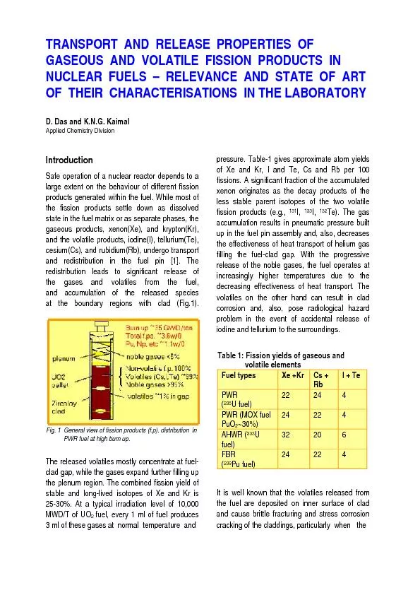
/
redistribution leads to significant release of redistribution leads to significant release of

redistribution leads to significant release of - PDF document

celsa-spraggs
celsa-spraggs . @celsa-spraggs
Follow
366 views
Uploaded On 2016-04-15

redistribution leads to significant release of - PPT Presentation

Fuel types Cs Rb I Te PWR 235U fuel 22 24 4 PWR MOX fuel PuO230 22 4 AHWR 233U fuel 32 20 6 FBR 239Pu fuel 24 22 4 Fig 1 General view of fission products fp ID: 280931

Fuel types

Share:

Link:

Embed:

Download Presentation from below link

Download Pdf The PPT/PDF document "redistribution leads to significant rele..." is the property of its rightful owner. Permission is granted to download and print the materials on this web site for personal, non-commercial use only, and to display it on your personal computer provided you do not modify the materials and that you retain all copyright notices contained in the materials. By downloading content from our website, you accept the terms of this agreement.


Presentation Transcript

redistribution leads to significant release of Fuel types Cs + Rb I + Te PWR (235U fuel) 22 24 4 PWR (MOX fuel PuO2~30%) 22 4 AHWR (233U fuel) 32 20 6 FBR (239Pu fuel) 24 22 4 Fig. 1 General view of fission products (f.p). distribution in PWR fuel at high burn up. that govern the redistribution behavior of the understand the extent of their release from the gases and volatiles are reported [1-3]. Fig. 2 Typical micrographic image of irradiated PWR fuel pin’s section showing the clad failure mechanism of the transports and releases of the fission gas and volatiles is known to be the thermal diffusion through lattice and grain in the either paths of release is exponentially dependent on he diffusion coefficient grows as D = D0 exp(-Q/RT), D0 and Q respectively being the jump frequency and the The thermal transport and release properties of the fission gases (Xe, Kr) and the volatiles (I, Te, Cs, Rb) depend on their physico-chemical states. uel pin results in the two distinct regions in the micrographic section in Fig.3a. Magnified view of the dispersed bubbles in the peripheral region of the fuel pin is shown in Fig.3b. Electron probe micro-analysis of the Xe profile across the burnt fuel rod corroborates to the Xe-depletion in the central region (Fig. 4). The gas atoms transport leading to their final release at fuel-clad interface occurs through the on, migration via micro cracks, and thermal sweeping of micro pores and grain boundaries themselves. The atoms residing temperature gradients to reach grain boundaries, voids and micro cracks, where they can accumulate as gas phase. Then resolution inside the ssion fragments, or get transported further out by the combined paths. Grain boundary transport is easier in general than the intra grain transport. The volatiles unlike the gases are not inert to the fuel matrix and to the other fission products. Transport paths of the volatiles are the same as those of the gases, but the driving forces for diffusions are gradients of their chemical potentials, the thermodynamic measures of reactivity of the diffusing species in their various he gradients, the volatile ed from one region of concentration and temperature to another in wer potential. Elemental ies in the fuel lattice. Like the gases, they remain mainly dispersed in fraction of Te remains dissolved in the alloy phases of the fission In order to analyse the release processes of the gas and volatile species from their complex x, it is necessary to measure the temperature dependent transport kinetics of the species [1,3]. For this, the matrix ities, specific surface area and initial concentrations of the diffusing Fig. 3 Typical micrographs of PWR fuel pin at high burn up. Fig 4. Xe profile across PWR fuel pin 1/2 Fig. 5 Schematic of PIA setup for Xe release Fi g . 6 Schematic of PIA setu p for I/Te release 1/21/2 Fig.7b HPGe with MCA facility Fi g . 7a PIA ex p erimental setu p for Xe release studie s Fig. 7c PIA experimental setup for I and Te release studies accepted as the most reasonable model for analysing the release of fission gases and volatiles from oxide fuels of the type UO2. It assumes that uniform spheres of theoretical density can represent the granular particles, and, even the sintered pellets with the same total surface area to volume ratio as that of the samples. The equivalent sphere radius a for a sample of specific surface area S is given by the relation, )/(3Sa where is theoretical density of fuel. The 2/12)/(6aDtf t. In the post irradiation annealing experiments, the diffusivity values D are evaluated from the observed slopes of the linear plots of f versus t of the species using the equivalent sphere radius a of the granular samples. The simple evaluation procedure described for the kinetic property (D) undergoes modification at high irradiation doses where there is significant micro structural D values together with the knowledge of the other kinetic parameters of the gas resolution, grain boundary sweeping and Experiments and Results Xenon release: Post-irradiation annealing experiments were made on thoria based fuel samples containing respectively 0.1 wt% and 1.0 wt% urania. The urania component was enriched with 235U fissile isotope to the extent of 93%. Two types of (Th,U) O2 fuel specimens were made for the purpose. The first type was sintered pellets of theoretical densities ranging from 67 to 94%. The second type was powder specimens prepared by crushing the sintered high density pellets and then sieving to extract the particle size in the average density as well as porosity of these specimens was measured by the CCl4 liquid displacement method. The total surface area was measured by the BET a for the particles was calculated. The a value calculated from the measured BET surface area of 240 cm2 g-1 was 12.5µm (Table 2). Table 2 : Characteristics of fuel samples for PIA studies Typically one gram of the specimens were irradiated in evacuated quartz ampoules in Apsara or CIRUS at different burn-up in the range of 2.8x10²⁰ to 2.8x1024 fissions/m3 (0.01 to 100 MWD T-1). The sample temperature during irradiation was estimated to be less than 700K. The capsules were stored for about 7 days in lived activities to decay. The irradiated specimens were transferred into t-irradiation annealing apparatus (schematics already shown in Fig. 5; photograph included in Fig. 7), where they were ling temperatures and the released gases were swept out with purified helium. The gas mixture passed through 133Xe isotope adsorbed in the trap was periodically counted 133 has a very high fission yield of about 6.5%. It is a days. The activity data obtained are considered as representative of other isotopes of the fission product xenon released. In order to calculate the fractional release, the total Xe133 initially in the specimen must be known. For this, a known amount of the 133 was adsorbed in the same charcoal trap and the activity was recorded. and the data analysis are given elsewhere [2]. A typical release behaviour of Xe133 from a 90%T.D. sintered pellet at different ranges of the anneal temperature is shown in Fig. 8a & b. The isothermal cumulative release grow nonlinearly to reach apparently a plateau region at the lower temperatures (Fig. 8a) where the steady state ll; the non-linear growth is due to the initial burst-release [2]. At higher near increase of the cumulative release with time as given in Fig.8b. Particle size Density BET surface Radius of equivalent sphere 37 to 45 m � 95% T.D. 240 cm2 g-1 12.5 m Fig. 8a Typical release behaviour of Xe133 at lower annealing temperatures of thoria fuel. Fig. 8b Typical release behavior of Xe133 at higher irradiation doses The apparent diffusivity D’= D/a2) was calculated from the slope of the steady state part obtained during six hours annealing time at each temperature. Temperature dependence of are shown in Fig.9. The activation energy values were evaluated from the plot of log D’ vs 1/T and found to be in the range of 196-242 kJ mol-1 which support the mechanism of atomic migration of xenon through the interstitials in ThO2 lattice [3]. The study with the varying densities of fuel samples showed that the extent of burst release and the diffusivity steeply fall to their limiting values as the density rises above 90%. Sharp fall in open porosity and 2O3) doped fuel samples. The nominal fall of the Xe diffusivity in the doped samples supported The other investigations which was carried out in al.[3]) was the study on the release kinetics of xenon in ThO2 (1273 - 1673K). It was observed that the diffusivity and the initial burst release are more or less dose independent up to the value of 21 fissions m3, and above it, they fall significantly to level off again beyond a dose of 23 fissions/m3 (Fig.10). The leveling of Xe transport at higher burn-up was explained on the assumption that at high dose irradiation a part of gas atoms are immobilized at the radiation induced trapping centres. The fraction of trapped doses were calculated and the damaged, or, void volume per fission, were -23 m3/fission) for the ThO2 matrix. The temperature trends of the measured diffusivities of Xe at the different doses were evaluated. The Arrhenius plot of DXe values at higher dose of 1.38x1024 fissions/m3 (Fig 9) showed two linear regions; the 41-50 kJ mol-1 higher slope in the upper temperature region is induced defects that annealed out at the higher temperatures. A similar effect was observed by Kaimal et al. [2] in 2 also as shown by the plot ‘c’ in Fig 9. Iodine and Tellurium release: Procedurally, the experimental steps in I and Te release were ts of thoria-2mol% urania were used to prepare powder samples 37-45 µm, grain density �95% of theoretical value, and BET surface of 240 cm2 g-1. Following the trace-irradiation at a dose of 5 x 10²⁰ fission m-3, and then cooling for seven days, the samples were annealed at 1200-1800 K in the PIA apparatus described earlier (Fig. 6). The Iodine and tellurium released from the sample inside a Fig .9 Temperature dependence of thermal diffusivity of Xe in thoria matrix Fig.10 Burn-up dependence Xe transport property The plots are represented in Fig. 11. For comparison sake, the reported behaviours of I and Te in pure urania fuel matrix [8] are included in the same figure. The figure suggests that both the volatile species are seen to have slower transports in thoria than in urania. The intercepts in Fig.11 representing the frequency factors D0 for the respective species are seen to be I and Te in thoria-2mol% urania fuel. in the same terminal block. This is