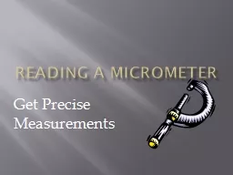
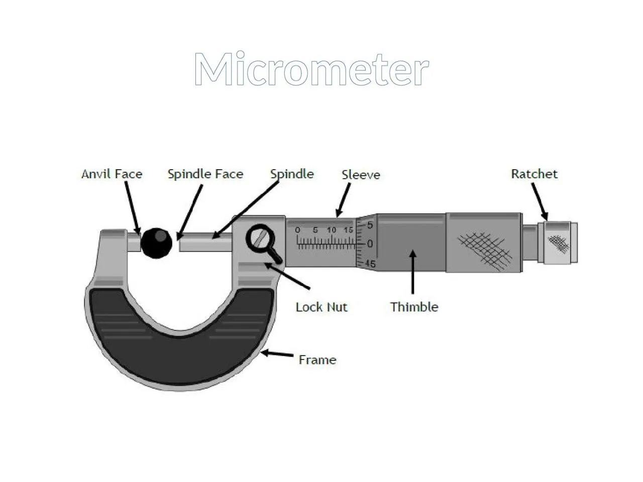
Reading a micrometer 1 The scale at the top of the sleeve measures every 1mm 2 The scale at the bottom of the sleeve measures every 05mm 3 The scale on the thimble measures every 001mm ID: 913332
Download Presentation The PPT/PDF document "Micrometer 1 2 3 The micrometer is a pre..." is the property of its rightful owner. Permission is granted to download and print the materials on this web site for personal, non-commercial use only, and to display it on your personal computer provided you do not modify the materials and that you retain all copyright notices contained in the materials. By downloading content from our website, you accept the terms of this agreement.
Slide1
Micrometer
Slide21
2
3
The micrometer is a precision measuring tool used in engineering. One full rotation of the ratchet moves the spindle face 0.5mm towards the anvil face. The ratchet is turned clockwise until the material is wedged tightly between the anvil and spindle faces.
Reading a micrometer
1. The scale at the top of the sleeve measures every 1mm.
2. The scale at the bottom of the sleeve measures every 0.5mm.
3. The scale on the thimble measures every 0.01mm.
Example 1
Top = 12mm
Bottom = 0.5mm
Thimble = 0.16mm
Total = 12.66mm
Slide3Slide43
0
0.26
3.26
10
0.5
0.16
10.66
16
0
0.16
16.16
Slide5Digital Vernier Calipers
The Digital
Caliper
is a precision instrument that can be used to measure internal and external distances extremely accurately. The example shown is a digital
caliper
as the distances/measurements, are read from a
LCD display
.
Slide6Manual versions of this type of measuring instrument had to be read by looking carefully at the imperial or metric scale and there was a need for very good eyesight in order to read the small sliding scale. Manually operated
vernier
calipers
can still be bought and remain popular because they are
much cheaper than the digital version. Also, the digital version requires a small battery whereas the manual version does not need any power source
.Digital calipers are easier to use as the measurement is clearly displayed and also, by pressing the inch/mm button the distance can be read as metric or imperial.
Slide7The display is turned on with the on/off button. The external jaws should then be brought together until they touch and the zero button should be pressed. The digital
caliper
can then be used to measure distances. Always go through this procedure when turning on the display for the first time.
MEASURING EXTERNAL DISTANCES
The material to be measured is placed between the external jaws and they are carefully brought together. The locking screw is tightened so that the jaws do not move apart. The digital display can then be read. The distance can be read by in metric and imperial by pressing the inch/mm button.
Slide8MEASURING INTERNAL DISTANCES
The example below shows a digital
caliper
being used to measure the internal diameter of a piece of copper tube. The internal jaws are adjusted carefully until they touch the internal ‘sides’. The locking screw is tightened so that an accurate measurement can be made even if the jaws are ‘knocked’ against the sides as the jaws are removed from the hole. The measurement is shown on the LCD display.
Slide9MEASURING DEPTHS
Measuring the depth of a hole can be very difficult. However, using a digital
caliper
makes this task easy. The base of the
vernier
caliper
rests on the top of the hole and the depth measuring blade is adjusted until it touches the bottom of the hole. The locking screw is tightened and the measurement can be read on the LCD display.
Slide10Manual Vernier Calipers
Slide11Example 1
13 + 0.42
= 13.42 mm
Slide12Example 2