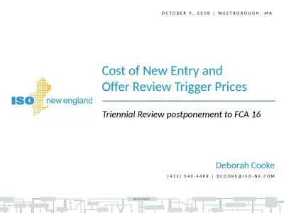
Reliability Committee amp Markets Committee Meeting 3 Considerations in the Design of Capacity Zones Al McBride MANAGER AREA TRANSMISSION PLANNING Presentation Objectives Introduce the ISO proposal at a high level ID: 815875
Download The PPT/PDF document "September 03, 2013 | Westborough, MA" is the property of its rightful owner. Permission is granted to download and print the materials on this web site for personal, non-commercial use only, and to display it on your personal computer provided you do not modify the materials and that you retain all copyright notices contained in the materials. By downloading content from our website, you accept the terms of this agreement.
Slide1
September 03, 2013 | Westborough, MA
Reliability Committee & Markets Committee Meeting #3
Considerations in the Design of Capacity Zones
Al McBride
MANAGER, AREA TRANSMISSION PLANNING
Slide2Presentation Objectives
Introduce the ISO proposal at a high level
Briefly review the Stakeholder discussions so farDiscuss examples of the capacity zone models in place in PJM and NYDiscuss the objective criteria (trigger) for the creation of zones (with examples)
Discuss export constrained zonesDiscuss the proposed process for the analysis of transfer limits and interfaces in the Regional System Planning (RSP) processDescribe what is proposed for FCA-9 and FCA-10 (and beyond)
Discuss next steps
2
Slide3High Level Summary of the ISO Proposal
For FCA-9 capacity zones would be created by implementing an objective criteria (automatic trigger) using the existing 8 energy zones as the starting point
The 8 energy load zones will serve as an approximation of the real transmission operating boundariesEnergy load zones that do not exceed the automatic trigger will be merged into the Rest-of-Pool Capacity zone
The objective criteria for the automatic creation of zones would be based on the TSA-like analysis of the energy zone along with the security constrained import analysis
For FCA-10 and beyond, incorporate the analysis of appropriate zonal boundaries into the annual process used to calculate transfer limits for RSP and NERC statutory requirements
The automatic trigger would continue to define whether a zone is modeled
3
Slide4Stakeholder Discussions
Al McBride
MANAGER, AREA TRANSMISSION PLANNING
Slide5Summary/Highlights
At the July 7, 2013 RC meeting we discussed
The requirements of the FERC orderThe constraints observed and expected on the New England systemThe methodologies in place to calculate requirements
Considerations in the design of capacity zonesThe timeline challenges associated with making changes for FCA-9
At the July 22 and 23, 2013 Summer RC meeting we discussed
The possibility of making some changes in time for FCA-9
On July 30, 2013, the ISO submitted the compliance timeline to FERC
http://www.iso-ne.com/regulatory/ferc/filings/2013/jul/er12-953-002_7-30-13_fcm_zone_compliance_filing.pdf
5
Slide6Summary/Highlights, continued
At the August 19, 2013 RC meeting we discussedThe capacity zone creation methodologies in place in PJM and New York
The Transmission Security Analysis (TSA) that has been performed in New England for the 8 Energy ZonesThe transmission transfer capability analysis processes in place in New England
Possible ways forward
6
Slide7Stakeholder Process
As defined by FERC
FERC has required the ISO to consider the following during the Stakeholder Process: “…(1)
the appropriate level of zonal modeling going forward; (2) the appropriate rules to govern intra- and inter-zonal transactions; and (3) whether
objective criteria by which zones may automatically be created
in response to rejected delist bids, generation retirements or other changes in system conditions would be appropriate in New England, or if not, why not.”
7
Docket No. ER12-953-002: Order Issued May 31, 2013
Slide8Subsequent Filing
As defined by FERC
FERC has required the ISO to make an additional filing at a later time to address: “…how it has addressed these items in its stakeholder process, and it must: (i)
develop and file with the Commission revisions to the ISO-NE tariff that articulate appropriate objective criteria to revise the number and boundaries of capacity zones automatically as the relevant conditions change
,
or
(ii) file with the Commission
an explanation as to why such criteria are unnecessary
.”
8
Docket No. ER12-953-002: Order Issued May 31, 2013
Slide9Capacity Zone Formation Methodologies in place in PJM and New York
Al McBride
MANAGER, AREA TRANSMISSION PLANNING
Slide10PJM Methodology Summary
A starting list of Locational
Deliverability Areas (LDAs) are defined in the PJM Reliability Assurance Agreement (RAA)The RAA lists a number of zones, most of which align with the footprints of the member Transmission Owning utilities or aggregations thereof
Any changes to the list of LDAs are those areas that have a limited ability to import capacity due to physical limitations of the transmission system, voltage limitations or stability limitations Identified by the load deliverability analyses conducted pursuant to the Regional Transmission Expansion Planning (RTEP) Protocol
10
Slide11PJM Methodology Summary, continued
A new LDA is created if such new LDA is projected to have a capacity emergency transfer limit (CETL) less than 1.15 times* the capacity emergency transfer objective (CETO) of such area, or if warranted by other reliability concerns consistent with the Reliability Principles and Standards
A FERC filing is made to amend the LDA list
11
*This trigger describes how capacity zones are automatically created in PJM
Slide12Cleveland LDAAn Example of How a New Zone is Created in PJM
12
Slide13Cleveland LDA, continued
An Example of How a New Zone is Created in PJM
As part of the 2012 RTEP process, PJM analyzed the need to model an LDA in the Cleveland areaA number of recent generator deactivation notices and transmission reinforcements in the Cleveland area drove the need in 2012 to consider establishing a new LDA
Transmission facilities in the Cleveland metropolitan area have been historically constrained by voltage and stability limitations as transfers into the area have risen over timeThese limitations have diminished the ability of Load Serving Entities (LSEs) to import power into the area
13
Slide14Cleveland LDA, continued
An Example of How a New Zone is Created in PJM
The peak load inside the interface is approximately 5,000 MWPreviously, Cleveland was part of the larger ATSI (formerly FirstEnergy) zone
The CETL/CETO ratio was actually found to exceed 1.15However, given that the “Cleveland Reactive Operational Interface” is an electrical area which PJM dispatchers already monitor to ensure reliability under real-time conditions, PJM selected it to become a new “Cleveland LDA”
The addition of the new zone was presented in the RTEP planning process and then filed at FERC
Approved by the FERC, effective January 4, 2013, the new LDA has been used for the first time in RTEP process studies in 2013 and for RPM activities in May 2013
14
Slide15NY Methodology Summary
NYISO’s aligns the process for creating a new capacity zone with the triennial ICAP demand curve reset process
NYISO begins the new capacity zone process with a New Capacity Zone Study (NCZ Study)If the NCZ Study identifies a Highway deliverability constraint (Highway constraint), NYISO will identify the boundary of a proposed new capacity zone
A locational minimum ICAP requirement is determined, followed by an analysis of a demand curve for the new capacity zone and submission to the Commission of tariff revisions to establish the new capacity zone
15
Slide16Lower Hudson Valley Zone
An Example of How a New Zone is Created in NY
In the recently completed NCZ study, NYISO identified the UPNY/SENY (Upstate New York/South East New York – located south of Albany) as a Highway deliverability constrainedThe NCZ study was discussed in the NY planning process
NYISO filed with FERC the creation of a new downstate zone which merges Zones G, H, I & JThis leaves New York with three zonesRest of State (approximately 13,000 MW)
“Lower Hudson Valley” (approximately 16,700 MW)
Long Island (Zone K, approximately 6,000 MW)
FERC approved the new zonal configuration in Docket No. ER13-1380-000
16
Slide17Automatic triggers for the modeling/creation of zones
Al McBride
MANAGER, AREA TRANSMISSION PLANNING
Slide18The Attributes of a Zone
The load in a zone is met by:the addition of:
Resources in the Zone + Import Capability
Simplified Example ZoneIn this case the load is exactly met
18
Load = 9,000 MW
Resources = 8,000 MW
Import Capability = 1,000 MW
Slide19Calculating Requirements
There are two ways to think about calculating requirements:
Resources: What amount of Resources are required for a given Import Capability?Or,
Import Capability: What amount of Import Capability is required for a given set of Resources?
Simplified Example Zone
19
Load = 9,000 MW
Resources = ? MW
Import Capability = ? MW
Slide20Which Import Capability?
It is required under the planning criteria to consider N-1-1 eventsThis discussion will focus on the N-1-1 Import Capability
This will be equivalent to the line-line calculations described in Transmission Security Assessments (TSA)
Simplified Example Zone
20
Load = 9,000 MW
Resources = ? MW
N-1-1
Import Capability = ? MW
Slide21Calculating a Transmission Security Requirement
A TSA Requirement is calculated as follows (simplified):
Assume resource unavailability of 5%
TSA Requirement = 5,263 MW
Simplified Example Zone
21
Load = 9,000 MW
N-1-1 Import Capability =
4,000 MW
(Load
–
Import Limit)
1 -
(resource unavailability factor)
TSA Requirement
(9,000
–
4,000)
1 -
(0.05)
TSA Requirement
Slide22Designing a Resource-Based Trigger
TSA Requirement = 5,263 MWUsing a 15% automatic trigger for modeling zones:
If there is more than 1.15*5,263 MW = 6,052 MW of Existing Resources in the zone,
then the zone would not be modeledNote: If there is more than 5,263 MW remaining in auction, the zone would not bind in the auction
Simplified Example Zone
22
Load = 9,000 MW
TSA = 5,263 MW
N-1-1 Import Capability =
4,000 MW
Slide23A Resource-Based Trigger Considering Potential Retirements
TSA Requirement = 5,263 MWThe largest resource in the zone is 1,000 MW
Using a potential retirement automatic trigger for modeling zones:If there is more than 5,263 + 1,000 =
6,263 MW of Existing Resources in the zone, then the zone would not be modeled
Simplified Example Zone
23
Load = 9,000 MW
TSA = 5,263 MW
N-1-1 Import Capability =
4,000 MW
The largest
Resource is
1,000 MW
Slide24A “Higher Of” Resource-Based Trigger
TSA Requirement = 5,263 MWIf the Existing Capacity of the Resources in the zone is greater than the higher of the [TSA*1.15] or the [
TSA+the largest resource], then the zone would not be modeled
Simplified Example Zone
24
Load = 9,000 MW
TSA = 5,263 MW
N-1-1 Import Capability =
4,000 MW
The largest
Resource is
1,000 MW
Slide25Designing an Import Limit-Based Trigger
(This approximates the PJM method)
What is the required Import Limit if the load is 7,000 MW and the Resources total 5,000 MWThe unavailability factor of the Resources should be considered (assume 5%)
Available Resources = 4,750 MW“Required” N-1-1 Import Capability = 2,250 MWIf the import capability is greater than 1.15*2,250 =
2,587 MW
, then the zone would not be modeled
Simplified Example Zone
25
Load = 7,000 MW
Resources = 5,000 MW
N-1-1 Import Capability =
? MW
Slide26An Import-Based Trigger Considering Potential Retirements
“Required” Import Capability = 2,250 MW
The largest resource in the zone is 1,000 MWIf the import capability is greater than 2,250 + 1,000 = 3,250 MW
, then the zone would not be modeled
Simplified Example Zone
26
Load = 7,000 MW
Resources = 5,000 MW
N-1-1 Import Capability =
? MW
The largest
Resource is
1,000 MW
Slide27A “Higher Of” Import Limit-Based Trigger
“Required” Import Capability = 2,250 MW
If the import capability is greater than [1.15*Required Import Capability] or [Required Import Capability + the largest resource], then the zone would not be modeled
Simplified Example Zone
27
Load = 7,000 MW
Resources = 5,000 MW
N-1-1 Import Capability =
? MW
The largest
Resource is
1,000 MW
Slide28What if the Import Capability of a Zone has not been calculated?
A zone could be evaluated based on its load and resources
If there is enough Existing Capacity in the zone (considering no import capability) to meet the load, then the zone would not be modeledIf some import capability is needed, N-1-1 power flow analysis can be used to confirm that the load can be served
This analysis would consider the unavailability of one or more resources
Simplified Example Zone
28
Load
Resources
Slide29Treatment of Export Constrained Zones
Al McBride
MANAGER, AREA TRANSMISSION PLANNING
Slide30Modeling Export Constrained Zones
What is the required Export Capability if the load is 2,000 MW and the Resources total 4,000 MW
The unavailability factor of the Resources should be considered (assume 5%)Available Resources = 3,800 MW
The Export Capability needs to be 3,800 – 2,000 = 1,800 MW to avoid locked-in capacityIf the export capability is greater than 1.15*1,800 = 2,070 MW, then the zone would not be modeled
Simplified Example Zone
30
Load = 2,000 MW
Resources = 4,000 MW
Export Capability = ? MW
Slide31Export Constrained Zones
Maine will continue to be evaluated for export constraintNorth of Orrington South will not be added as a capacity zone
There is no reliability benefit or need to do thisFor FCA-9, the smallest building block is the Load Zone
31
Slide32Modeling SEMA/RI
SEMA/RI (Southeast Massachusetts/Rhode Island) has been identified as export constrained for many years
The only interface currently available to System Planning that could be associated with modeling the SEMA/RI zones is the SEMA/RI Export Limit3,000 MW through 2017
3,400 MW after 2017
SEMA/RI
32
RI
SEMA
Slide33Modeling SEMA/RI, continued
When Resource unavailability is considered, SEMA/RI does not appear to be export constrained at peak load
The ISO does not propose to consider evaluating SEMA-RI as export constrained in FCA-9
SEMA/RI – FCA-5 Values
90/10 Load = 6,235 MW
Resources = 9,360 MW
33
RI
SEMA
Slide34Annual Planning process:
Proposed Alignments, and enhancements
Al McBride
MANAGER, AREA TRANSMISSION PLANNING
Slide3535
FAC-013-2
NERC Standard FAC-013-2 ensures that Planning Coordinators have a methodology for, and perform an annual assessment to identify
potential future Transmission System weaknesses and limiting facilities that could impact the Bulk Electric System’s ability to reliably transfer energy
in the Near-Term Transmission Planning Horizon
In New England, when identifying potential future Transmission System weaknesses, consideration will be given
to
rejected delist bids, generation retirements or other changes in system conditions
Near-Term Transmission Planning Horizon = the transmission planning period that covers years one through five.
Slide36Alignment of Planning Processes
NERC FAC-013-2 activities have been brought in alignment withFERC 715 reporting of various aspects the transmission system and the transmission planning process
The calculation of future transmission limits needed for various activities and documented in the Regional System Plan
The following slide contains the most recent presentation of transfer capabilities that were provided to the Power Supply Planning Committee at their June 3, 2013 meeting
36
Slide37RSP13 Base Interface Limits
37
Notes are discussed in Appendix 1 of this presentation
Single-Value, Summer
Peak,
1
Non-Firm
, Transmission Interface Limits for Use in
Subarea Transportation Models
Interface
2013
2014
2015
2016
2017
2018
2019
2020
2021
2022
New Brunswick-New England
700
2
700
2
700
2
700
2
700
2
700
2
700
2
700
2
700
2
700
2
Orrington South Export
1200
1200
1325
a
1325
1325
1325
1325
1325
1325
1325
Surowiec South
1150
1150
1500
a
1500
1500
1500
1500
1500
1500
1500
Maine-New Hampshire
1600
1600
1900
a
1900
1900
1900
1900
1900
1900
1900
North-South
2700
2700
2700
2700
2700
2700
2700
2700
2700
2700
East-West
2800
2800
2800
2800
2800
3500
b
3500
3500
3500
3500
West-East
1000
1000
1000
1000
1000
2200
b
2200
2200
2200
2200
Boston Import (N-1)
4900
4850
c
4850
4850
d
4850
4850
4850
4850
4850
4850
Boston Import (
N-1-1)
3700
4175
c
4175
4175
d
4175
4175
4175
4175
4175
4175
SEMA Export
No Limit
No Limit
No Limit
No Limit
No Limit
No
Limit
No
Limit
No
Limit
No
Limit
No
Limit
SEMA/RI Export
3000
3000
3000
3000
3000
3400
b
3400
3400
3400
3400
Connecticut Import (N-1)
3050
e
3050
3050
3050
2800
f
2950
b
2950
2950
2950
2950
Connecticut Import (
N-1-1)
1850
e
1850
1850
1850
1600
f
1750
b
1750
1750
1750
1750
SW
Connecticut Import (N-1)
3200
3200
3200
3200
3200
3200
3200
3200
3200
3200
Norwalk / Stamford
1650
1650
1650
1650
1650
1650
1650
1650
1650
1650
HQ-NE (Highgate)
200
200
200
200
200
200
200
200
200
200
HQ-NE (Phase
II)
3
1400
1400
1400
1400
1400
1400
1400
1400
1400
1400
Cross-Sound Cable (CSC) (In)
4
0
0
0
0
0
0
0
0
0
0
Cross-Sound Cable (CSC) (Out)
346
346
346
346
346
346
346
346
346
346
NY-NE Summer
5
1400
1400
1400
1400
1400
1400
1400
1400
1400
1400
NY-NE Winter
5
1875
1875
1875
1875
1875
1875
1875
1875
1875
1875
NE-NY Summer
5
1200
1200
1200
1200
1200
1200
1200
1200
1200
1200
NE-NY Winter
5
1400
1400
1400
1400
1400
1400
1400
1400
1400
1400
Slide38Assessment of New Interfaces
NERC FAC-013-2 activities will be further enhanced to incorporate the examination of future capacity zones and associated transfer capabilities
The transfer capability assessment will include the review of whether additional interfaces would be required in the case of submitted or potential resource retirements
38
Slide39Attachment K
Attachment K of the ISO New England Open Access Transmission Tariff (OATT) describes the Regional System Planning (RSP) Process in New England
According to Attachment K, the RSP shall, among other things:describe, in a consolidated manner, the assessment of the PTF system needs, the results of such assessments, and the projected improvements;
provide the projected annual and peak demands for electric energy for a five-to ten-year horizon, the needs for resources over this period and how such resources are expected to be provided; specify the physical characteristics of the physical solutions that can meet the needs defined in the Needs Assessments and include information on market responses that can address them; and
provide sufficient information to allow Market Participants to assess the quantity, general locations, operating characteristics and required availability criteria of the type of incremental supply or demand-side resources, or merchant transmission projects, that would satisfy the identified needs or that may serve to modify, offset or defer proposed regulated transmission upgrades.
39
Slide40Attachment K, continued
According to Attachment K, one of the triggers for a Needs Assessment is:
constraints or available transfer capability limitations that are identified possibly as a result of generation additions or retirements, evaluation of load forecasts or proposals for the addition of transmission facilities in the New England Control AreaIn addition Needs Assessments are conducted for Rejected Non-Price Retirement Requests and De-List Bids
On-going Needs Assessments reflect Resources with Non-Price Retirement Requests or Permanent De-List Bids as unavailable for reliabilityNew Needs Assessments may be initiated
40
Slide41Proposed addition to Attachment K
The annual Transfer Capability Assessment, conducted pursuant to NERC Standard FAC-013-2, and the identification of any new interfaces will be a part of the annual RSP process
The annual assessment will include the consideration of the addition of new interfaces that would result from submitted or potential retirements of resources
41
Slide42Requirements Calculations
A new interface and associated zone will be included in the preparation for a given FCA if the transfer capability analysis is complete in time for the requirement calculation process for the FCA
Zones that do not trigger the automatic criteria are merged into the Rest-of-Pool zoneThe requirements calculations for the new capacity zone will follow the normal stakeholder review process used for FCA requirements calculations
The LSR and MCL requirements calculations for import- and export-constrained zones will be unchangedThe higher of the Transmission Security Assessment and the Local Resource Adequacy will be used to set LSR
42
Slide43FERC Filing
The zonal requirement of any new zone, along with the associated transfer capability will be included in the pre-FCA FERC filings
43
Slide44Vermont ZoneExample of How a New Zone Could be Evaluated in the Planning Process
In response to repeated requests to de-list generation in Vermont, the ISO had begun the process of defining an interface and calculating a transfer capability into Vermont
The ISO will evaluate the modeling of a Vermont Zone in FCA-9
In response to a request to retire generation Will be discussed in the RSP process in 2014
Vermont Zone
44
Slide45SEMA/RIExample of How a New Zone Could be Evaluated in the Planning Process
SEMA/RI is a good example of why the load zone boundaries are not necessarily useful interfaces for modeling capacity zones
Some are perhaps counter-productive
For FCA-10 and beyond, the planning process can evaluate the addition of a more appropriate interface to manage the issues that could drive the need for a capacity zone
SEMA/RI – FCA-5 Values
90/10 Load = 6,235 MW
Resources = 9,360 MW
45
RI
SEMA
?
?
Slide46Other Issues
Slide47Minimum Zone Size
The zones modeled in PJM and New York are relatively large (many 1,000s MW)Many zones are merged together in the absence of triggering the objective criteria
ISO New England proposes to remain focused on the more significant load serving constraintsInterregional Operating Limits (IROLs)
Rule of thumb minimum IROL size is 1,200 MW of transfer capability or served load
47
Slide48The Role of Market Resource Alternatives
Market Resource Alternatives (MRAs – also known as Non-Transmission Alternatives or NTAs) are, by definition, a consideration in the long-term transmission planning space
If NTAs become committed through the Forward Capacity Market or appropriate contract, they would be reflected in the zonal modeling process
48
Slide49Listing of the iso
proposal
Slide50ISO Proposal for The Management of Capacity Zones
In Market Rule 1, Section 12 add automatic trigger(s) for the modeling and creation of zones
For FCA-9 capacity zones would be created by implementing the objective criteria (automatic trigger) using the existing 8 energy zones as the starting point
The 8 energy zones will serve as an approximation of the real transmission operating boundaries
Energy
zones
that do not exceed the automatic trigger will be collapsed into the Rest-of-Pool Capacity zone
The objective criteria for the automatic creation of zones would be based on the TSA-like analysis of the energy zone along with the security constrained import analysis
For FCA-10 and beyond, incorporate the analysis of appropriate zonal boundaries into the annual process used to calculate transfer limits for RSP and NERC statutory requirements
The automatic trigger would continue to define whether the zone would be created
50
Slide51ISO Proposal for The Management of Capacity Zones, continued
In conducting compliance transfer capability analysis pursuant to FAC-013-2, include the review of whether new interfaces should be added based on submitted or potential retirements
Add to Attachment K the presentation of the annual transfer capability assessments as part of the annual RSP process
Once a zone is modeled in the FCA, it will persist in the subsequent reconfiguration auctions and bilateral transaction windows for that Capacity Commitment Period
No change to bilateral trading rules
51
Slide52Steps to implementation
Slide53Steps to Completion
Changes to Market Rule 1 Section 12
Reliability CommitteeChanges to Planning Procedure 10
Reliability CommitteeChanges to Attachment K?Transmission CommitteeChanges to Market Rule 1 Section 13?
Markets Committee
FERC Filing
53
Slide54Schedule for Implementation
Implementation for FCA #9:
54
Dates
Discussion Topics
Jul - Sep 2013
Discuss current methodologies and explore new methodologies for determining zones and requirements while
minimally
changing other aspects of the FCM
Sep - Nov 2013
Finalize principles for zone creation
Nov 2013 - Jan 2014
Define zones and finalize zonal requirements; begin Tariff language changes
RC (with MC invitation) Action
Jan - Feb 2014
NPC Action
Early March 2014
FERC Filing of Tariff Changes
Late March 2014
FERC Order*
Late May 2014
* FERC Order to be received after opening of the Show of Interest Window but before New Capacity Qualification Deadline and De-list Bid Deadline
Slide55Appendix 1:
Notes to the RSP13 Base interface limits
Al McBride
MANAGER, AREA TRANSMISSION PLANNING
Slide56RSP13 Base Interface Limits
Limits are for the Summer period, except where noted to be winter
The limits do not include possible simultaneous impacts, and should not be considered as “firm” (the bases for these limits are subject to more detailed review in the future)
For the years within the Forward Capacity Market (FCM) horizon (2017 [Forward Capacity Auction 8] and sooner), only certified transmission upgrades are included when identifying transfer limits
For the years beyond the FCM horizon (2018 and later), proposed plan approved transmission upgrades are included according to their expected in-service dates
56
Slide57RSP13 Base Interface Limits, continued
Relevant in-service dates
Maine Power Reliability Program – 2015
NEEWS Interstate Reliability Program – 12/2015 (However, not all portions of this project have been certified to be in service by 2017)
The Boston import capabilities change in 2014 as a result of the combination of the retirement of Salem Harbor and the inclusion of the advanced NEMA/Boston upgrades
The effect of the addition of the Footprint generation project on the Boston import capability will be evaluated at a future date
NEEWS Greater Springfield Reliability Program – 2013
With the certification of the new 345 kV Lake Road-Card line, the Lake Road generating facility will be modeled in the Connecticut zone for Capacity Commitment Period 8 (2017)
The 345 kV Lake Road-Card line was certified to be in-service by 2016. It is under review whether Lake Road will be modeled in the Connecticut zone for Capacity Commitment Period 7 (2016) .
57
Slide58RSP13 Base Interface Limits, continued
The electrical limit of the New Brunswick-New England (NB-NE) Tie is 1,000 MW
When adjusted for the ability to deliver capacity to the greater New England Control area, the NB-NE transfer capability is 700 MW
This is because of downstream constraints; in particular Orrington South
The Hydro-Quebec Phase II interconnection is a DC tie with equipment ratings of 2,000 MW. Due to the need to protect for the loss of this line at full import level in the PJM and NY Control Areas’ systems, ISO-NE has assumed its transfer capability for capacity and reliability calculation purposes to be 1,400 MW
This assumption is based on the results of loss-of-source analyses conducted by PJM and NY
58
Slide59RSP13 Base Interface Limits, continued
Import capability on the Cross Sound Cable (CSC) is dependent on the level of local generation
New York interface limits
These are without CSC and with the Northport Norwalk Cable at 0 MW flow
Simultaneously importing into NE and SWCT or CT can lower the NY-NE capability (very rough decrease = 200 MW)
Simultaneously exporting to NY and importing to SWCT or CT can lower the NE-NY capability (very rough decrease = 700 MW)
59
Slide60Appendix 2:
TSA Calculations for FCA-5
Al McBride
MANAGER, AREA TRANSMISSION PLANNING
Slide61FCA-5 TSA Requirements
Review the assumptions, methodology and Transmission Security Analysis (TSA) requirements for the 2014-2015 Capacity Commitment Period (FCA-5)in New England
The methodology and assumptions used to determine the 2014/15 TSA requirements were developed in accordance with section III.12.2.1.2. of Market Rule 1, and section 6 of ISO Planning Procedure 10 – Planning Procedure to Support the Forward Capacity Market
61
Slide62FCA-5 TSA Requirements - Model
The calculation of the FCA-5 local capacity requirements, including the TSA requirements, relied on the latest available data
Load forecast, resource data and resource availability were presented to the Power Supply Planning Committee on 12/06/2010; details are available at:http://www.iso-ne.com/committees/comm_wkgrps/relblty_comm/pwrsuppln_comm/mtrls/2010/dec62010/index.html
The transmission topology that was certified for FCA-5 was introduced at the 09/20/10 Reliability Committee; details are available at:
http://www.iso-ne.com/markets/othrmkts_data/fcm/qual/models/index.html
62
Slide63Methodology
The TSA determines the requirement of an area (in the case of FCA-5 the energy load zone) to meet its load through internal generation and import capability
It stems from ISO Planning Procedure 3 - Reliability Standards for the New England Area Bulk Power Supply System key transmission security requirementsIdentify all resources and serve area load under N-1 and N-1-1 conditions
Perform review under reasonably stressed conditions (“With due allowance for generator maintenance and forced outages”)It is performed via a series of transmission load flow studies
In performing the analysis, static transmission interface transfer limits may be established as a reasonable representation of the transmission system’s capability to serve sub-area load with available existing resources
Results may be presented in the form of a deterministic operable capacity analysis
63
Slide64Methodology, continued
When presented in the form of a deterministic operable capacity analysis, the TSA compares need with available resources
Needs includeLoad + Loss of Generator (“Line-Gen” scenario), or
Load + Loss of import capability (going from an N-1 import capability to an N-1-1 import capability; “Line-Line” scenario)Resources includeN-1 Import capability
Regular generation
Operating actions (fast start units, demand response…)
Resource unavailability is applied by de-rating capacity
Example
Subarea
90/10
Load
8 300
Reserves (Largest
unit or loss
of import capability
)
1 200
Subarea Transmission Security
Need
9 500
Existing Resources
10 000
Assumed
Unavailable
Capacity
500
Subarea N-1 Import Capability
2 500
Subarea Available
Resources
12 000
Subarea Transmission
Security
Margin
2 500
64
Slide65Methodology, continued
For each of the potential import constrained Capacity Zones, the TSA requirement (resource requirement that will be compared to the Local Resource Adequacy Requirement) is the amount of internal resources (generators and Demand Resources) needed in the zone, so that the Line-Line or Line-Gen requirements can be met after proper accounting for resource unavailability
The TSA requirement can be approximated by using the following formula
(Need – Import Limit)
1 - ( Assumed Unavailable Capacity / Existing Resources)
TSA Requirement
65
Slide66Methodology, continued
Example:
Subarea
90/10
Load
8 300
Reserves (Largest
unit or loss
of import capability
)
1 200
Subarea Transmission Security
Need
9 500
Existing Resources
10 000
Assumed
Unavailable
Capacity
500
Subarea N-1 Import Capability
2 500
Subarea Available
Resources
12 000
Subarea Transmission
Security
Margin
2 500
(
9,500
–
2,500
)
1 - (500/
10,000
)
TSA Requirement
7,368
MW
66
Slide67Methodology, continued
The application of the TSA requirement calculation using energy load zones is an approximation, due to:
The use of static transmission interface transfer limitsThe reliance on specific scenarios (“Line-Gen”) and (“Line-Line”)
The nature of the calculationThe term [Assumed Unavailable Capacity / Existing Resource] in the above equation depends on the actual proportion of regular generation, peaking generation, intermittent resources, Real-Time Emergency Generation (RT-EG), active non-RTEG Demand Resources (DR) and passive DR
The fact that the energy load zones boundaries do not exactly correspond to the real transmission operating boundaries
Real transmission operating boundaries are based on the limiting constraints that define a geographic areas (within which resources have a very high probability of substitutability) import capability and the ability of the resources within the zone to alleviate those constraints
The TSA requirement should be calculated based on an area’s real transmission operating boundaries. However, the TSA calculation using energy load zones could serve as an approximation for what the requirement would be for the geographic area that contains an individual or combined energy load zone.
67
Slide68FCA-5 TSA Requirements and Related Analysis, cont.
TSA requirements were calculated for both a “Line-Gen” and “Line-Line” scenario
As a worst-case sensitivity analysis, TSA requirements were also calculated for the New Hampshire, Rhode Island, SEMASS, WCMASS and Vermont Load Zones; a worst-case assumption of 0 MW
of N-1 and N-1-1 import transfer capability was initially assumed for these Load Zones
As further sensitivity, a Capacity Zone determination was performed
It was assumed that in every Load Zone, the Local Sourcing Requirement would be set by the TSA requirement
The determination was based on the methodology described in section III.12.4 of Market Rule 1
68
Slide69FCA-5 TSA Requirements – Line-Gen
69
All values in MW
Slide70FCA-5 TSA Requirements – Line-Line
70
All values in MW
Slide71FCA-5 TSA Requirements - Results
The Load Zone sensitivity analysis showed that
Regardless of their N-1 or N-1-1 import capability, there was no need to form separate capacity zones for New Hampshire or SEMASS, because the revised amount of capacity to be compared to the export-adjusted LSR could not be lower than the export-adjusted LSR
Under the worst-case assumption where the N-1 or N-1-1 import capability into Rhode Island, WCMASS and Vermont is below the required import capability shown below, the revised amount of capacity to be compared to the export –adjusted LSR can be less than the export-adjusted LSR; however, these Load Zones’ interfaces are such that they include many 345kV, 230kV or 115kV ties; therefore, there is still no need to form separate capacity zones for Rhode Island, WCMASS and Vermont
71
Load Zone
Required Import Capability (MW)
Load Zone Interface Characteristics
Rhode
Island
N-1: 38 MW
3
345kV and 8 115kV paths into the load pocket
WCMASS
N-1: 509 MW
N-1-1: 194 MW
8 345kV,
2 230kV and 15 115kV paths into the load pocket
Vermont
N-1: 528 MW
2 345kV, 1 230kV and 7 115kV paths into the load
pocket
Compare with PJM’s capacity emergency transfer objective
Slide7272