/
Fracture Mechanics Fracture Mechanics

Fracture Mechanics - PowerPoint Presentation

conchita-marotz
conchita-marotz . @conchita-marotz
Follow
452 views
Uploaded On 2017-03-26

Fracture Mechanics - PPT Presentation

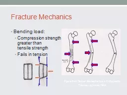
Bending load Compression strength greater than tensile strength Fails in tension Figure from Tencer Biomechanics in Orthopaedic Trauma Lippincott 1994 Fracture Mechanics Torsion ID: 529500

biomechanics plate screws fixation plate biomechanics fixation screws bone locked fracture frigg robi courtesy synthes screw figure plating external

Share:

Link:

Embed:

Download Presentation from below link

Download Presentation The PPT/PDF document "Fracture Mechanics" is the property of its rightful owner. Permission is granted to download and print the materials on this web site for personal, non-commercial use only, and to display it on your personal computer provided you do not modify the materials and that you retain all copyright notices contained in the materials. By downloading content from our website, you accept the terms of this agreement.


Presentation Transcript

Slide1

Fracture Mechanics

Bending load:Compression strength greater than tensile strengthFails in tension

Figure from:

Tencer

. Biomechanics in

Orthopaedic

Trauma, Lippincott, 1994.Slide2

Fracture Mechanics

Torsion

The diagonal in the direction of the applied force is in tension – cracks perpendicular to this tension diagonal

Spiral fracture 45

º

to the long axis

Figures from:

Tencer

. Biomechanics in

Orthopaedic

Trauma, Lippincott, 1994.Slide3

Fracture Mechanics

Combined bending & axial loadOblique fractureButterfly fragment

Figure from:

Tencer

. Biomechanics in

Orthopaedic Trauma, Lippincott, 1994.Slide4

Biomechanics of Internal Fixation

Screw AnatomyInner diameterOuter diameterPitch

Figure from:

Tencer

et al, Biomechanics in

OrthopaedicTrauma, Lippincott, 1994.Slide5

Biomechanics of Screw Fixation

To increase strength of the screw & resist fatigue failure:Increase the inner root diameter

To increase pull out strength of screw in bone:

Increase outer diameterDecrease inner diameter

Increase thread densityIncrease thickness of cortexUse cortex with more density.Slide6

Biomechanics of Screw Fixation

Cannulated ScrewsIncreased inner diameter required Relatively smaller thread width results in lower pull out strengthScrew strength minimally affected

r4

outer core - r4inner core )

Figure from:

Tencer et al, Biomechanics in

OrthopaedicTrauma, Lippincott, 1994.Slide7

Biomechanics of Plate Fixation

Plates: Bending stiffness proportional to the thickness (h) of the plate to the 3rd power.

I= bh

3

/12

Base (b)

Height (h)Slide8

Moments of Inertia

Resistance to bending, twisting, compression or tension of an object is a function of its shapeRelationship of applied force to distribution of mass (shape) with respect to an axis.

Figure from: Browner et al, Skeletal Trauma 2nd Ed, Saunders, 1998.

 Slide9

Fracture Mechanics

Fracture CallusMoment of inertia proportional to r4

Increase in radius by callus greatly increases moment of inertia and stiffness

1.6 x stronger

0.5 x weaker

Figure from: Browner et al, Skeletal Trauma

2nd Ed, Saunders, 1998.

Figure from:

Tencer

et al: Biomechanics in

Orthopaedic Trauma, Lippincott, 1994.Slide10

Fracture Mechanics

Time of HealingCallus increases with timeStiffness increases with time

Near normal stiffness at 27 days

Does not correspond to radiographs

Figure from: Browner et al, Skeletal Trauma,

2nd Ed, Saunders, 1998.Slide11

IM Nails

Moment of InertiaStiffness proportional to the 4

th power.

Figure from: Browner et al, Skeletal Trauma, 2nd Ed, Saunders, 1998.Slide12

IM Nail Diameter

Figure from:

Tencer

et al, Biomechanics in

Orthopaedic

Trauma, Lippincott, 1994.Slide13

Slotting

Figure from:

Tencer

et al, Biomechanics

in

Orthopaedic

Trauma, Lippincott, 1994.

Figure from Rockwood and Green

s, 4

th

Ed 

Allows more flexibility

In bending

Decreases torsional strengthSlide14

Slotting-Torsion

Figure from:

Tencer

et al, Biomechanics

in

Orthopaedic

Trauma, Lippincott, 1994.Slide15

Interlocking Screws

Controls torsion and axial loads

Advantages

Axial and rotational stabilityAngular stability

DisadvantagesTime and radiation exposureStress riser in nailLocation of screwsScrews closer to the end of the nail expand the zone of fxs that can be fixed at the expense of construct stabilitySlide16

Biomechanics of Internal FixationSlide17

Biomechanics of Plate Fixation

Functions of the plateCompressionNeutralizationButtress

“The bone protects the plate

”Slide18

Biomechanics of Plate Fixation

Unstable constructsSevere comminutionBone loss

Poor quality bonePoor screw techniqueSlide19

Biomechanics of Plate Fixation

Fracture Gap /ComminutionAllows bending of plate with applied loads

Fatigue failure

Applied Load

Bone

Plate

GapSlide20

Biomechanics of Plate Fixation

Fatigue FailureEven stable constructs may fail from fatigue if the fracture does not heal due to biological reasons.Slide21

Biomechanics of Plate Fixation

Bone-Screw-Plate RelationshipBone via compression

Plate via bone-plate frictionScrew via resistance to bending and pull out.

Applied LoadSlide22

Biomechanics of Plate Fixation

The screws closest to the fracture see the most forces.The construct rigidity decreases as the distance between the innermost screws increases.

Screw Axial ForceSlide23

Biomechanics of Plate Fixation

Number of screws (cortices) recommended on each side of the fracture:

Forearm 3 (5-6)

Humerus 3-4 (6-8)

Tibia 4 (7-8) Femur 4-5 (8) Slide24

Biomechanics of Plating

Tornkvist H. et al: JOT 10(3) 1996, p 204-208Strength of plate fixation ~ number of screws & spacing (1 3 5 > 123)Torsional strength ~ number of screws but not spacingSlide25

Biomechanics of External FixationSlide26

Biomechanics of External Fixation

Pin Size{Radius}4

Most significant factor in frame stabilitySlide27

Biomechanics of External Fixation

Number of PinsTwo per segmentThird pinSlide28

Biomechanics of External Fixation

A

B

C

Third pin (C) out of plane of two other pins (A & B) stabilizes that segment.Slide29

Biomechanics of External Fixation

Pin LocationAvoid zone of injury or future ORIFPins close to fracture as possible

Pins spread far apart in each fragmentWires

90ºSlide30

Biomechanics of External Fixation

Bone-Frame DistanceRodsRings

DynamizationSlide31

Biomechanics of External Fixation

SUMMARY OF EXTERNAL FIXATOR STABILITY: Increase stability by:

1] Increasing the pin diameter.

2] Increasing the number of pins.

3] Increasing the spread of the pins. 4] Multiplanar fixation.

5] Reducing the bone-frame distance. 6] Predrilling and cooling (reduces thermal necrosis). 7] Radially preload pins.

8] 90 tensioned wires. 9] Stacked frames. **but a very rigid frame is not always good.Slide32

Ideal Construct

Far/Near - Near/Far on either side of fxThird pin in middle to increase stabilityConstruct stability compromised with spanning ext fix – avoid zone of injury (far/near – far/far)Slide33

Biomechanics of Locked PlatingSlide34

Patient Load

Conventional Plate Fixation

Patient Load

<

=

Friction Force

Patient Load

Courtesy of Synthes- Robi FriggSlide35

Locked Plate and Screw Fixation

Patient Load

=

<

Compressive Strength of the Bone

Courtesy of Synthes- Robi FriggSlide36

Stress in the Bone

Patient Load

+

Preload

Courtesy of Synthes- Robi FriggSlide37

Standard versus Locked Loading

Courtesy of Synthes- Robi FriggSlide38

Pullout of regular screws

by bending load

Courtesy of Synthes- Robi FriggSlide39

Higher resistant LHS against bending load

Larger resistant area

Courtesy of Synthes- Robi FriggSlide40

Biomechanical Advantages of Locked Plate Fixation

Purchase of screws to bone not critical (osteoporotic bone)Preservation of periosteal blood supply

Strength of fixation rely on the fixed angle construct of screws to plate

Acts as “

internal” external fixator Slide41

Preservation of Blood Supply

Plate Design

DCP

LCDCPSlide42

Preservation of Blood Supply

Less bone pre-stress

Conventional Plating

Bone is pre-stressed

Periosteum strangled

Locked Plating

Plate (not bone) is pre-stressed

Periosteum preserved

Courtesy of Synthes- Robi FriggSlide43

Angular Stability of Screws

Locked

Nonlocked

Courtesy of Synthes- Robi FriggSlide44

Biomechanical principles

similar to those of external fixators

Stress distribution

Courtesy of Synthes- Robi FriggSlide45

Surgical Technique

Compression Plating

The contoured plate maintains anatomical reduction as compression between plate and bone is generated.

A well contoured plate can then be used to help reduce the fracture.

Traditional Plating

Courtesy of Synthes- Robi FriggSlide46

Surgical Technique

Reduction

If the same technique is attempted with a locked plate and locking screws, an anatomical reduction will not be achieved.

Locked Plating

Courtesy of Synthes- Robi FriggSlide47

Surgical Technique

Reduction

Instead, the fracture is

first

reduced and then the plate is applied.

Locked Plating

Courtesy of Synthes- Robi FriggSlide48

Surgical Technique

Precontoured Plates

1. Contour of plate is important to maintain anatomic reduction.

Conventional Plating

Locked Plating

1. Reduce fracture prior to applying locking screws.Slide49

Biomechanical Advantage

Unlocked

vs

Locked Screws

1. Force distribution

2. Prevent primary reduction loss

Sequential Screw Pullout

Larger area of resistance

3. Prevent secondary reduction loss

4.

Ignores

opposite cortex integrity

5. Improved purchase on osteoporotic boneSlide50

Surgical Technique

Reduction with Combination Plate

Lag screws can be used to help reduce fragments and construct stability improved w/ locking screws

Locked Plating

Courtesy of Synthes- Robi FriggSlide51

Surgical Technique

Reduction with Combination Hole Plate

Lag screw must be placed 1

st

if locking screw in same fragment is to be used.

Locked Plating

Courtesy of Synthes- Robi FriggSlide52

Hybrid Fixation

Combine benefits of both standard & locked screwsPrecontoured plateReduce bone to plate, compress & lag through plate

Increase fixation with locked screws at end of constructSlide53

Length of Construct

Longer spread with less screws“Every other”

rule (3 screws / 5 holes)< 50% of screw holes filledAvoid too rigid constructSlide54

Biomechanical Advantages of Locked Plate Fixation

Purchase of screws to bone not critical (osteoporotic bone)Preservation of periosteal blood supply

Strength of fixation rely on the fixed angle construct of screws to plate

Acts as “

internal” external fixator