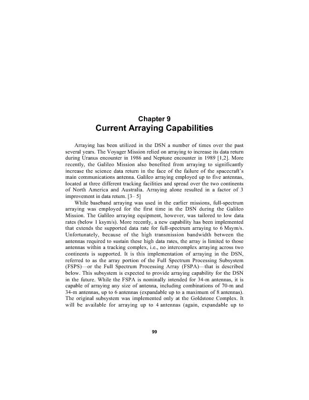
/
recently, the Galileo Mission also benefited from arraying to signific recently, the Galileo Mission also benefited from arraying to signific

recently, the Galileo Mission also benefited from arraying to signific - PDF document

conchita-marotz
conchita-marotz . @conchita-marotz
Follow
384 views
Uploaded On 2016-05-11

recently, the Galileo Mission also benefited from arraying to signific - PPT Presentation

8 antennas at the end of 2003 at the overseas complexes Madrid Spain and91Equipment Descriptioninputs are individual 300MHz intermediate frequency IF analog signals FSR on the left and the FS ID: 314924

antennas) the end

Share:

Link:

Embed:

Download Presentation from below link

Download Pdf The PPT/PDF document "recently, the Galileo Mission also benef..." is the property of its rightful owner. Permission is granted to download and print the materials on this web site for personal, non-commercial use only, and to display it on your personal computer provided you do not modify the materials and that you retain all copyright notices contained in the materials. By downloading content from our website, you accept the terms of this agreement.


Presentation Transcript

recently, the Galileo Mission also benefited from arraying to significantlyincrease the science data return in the face of the failure of the spacecraftsmain communications antenna. Galileo arraying employed up to five antennas,located at three different tracking facilities and spread over the two continentsof North America and Australia. Arraying alone resulted in a factor of 3improvement in data return. [3… 5]While baseband arraying was used in the earlier missions, full-spectrumarraying was employed for the first time in the DSN during the GalileoMission. The Galileo arraying equipment, however, was tailored to low datarates (below 1 ksym/s). More recently, a new capability has been implementedthat extends the supported data rate for full-spectrum arraying to 6 Msym/s.34-m antennas, up to 6 antennas (expandable up to a maximum of 8 antennas).will be available for arraying up to 4 antennas (again, expandable up to 8 antennas) at the end of 2003 at the overseas complexes (Madrid, Spain, and9.1Equipment Descriptioninputs are individual 300-MHz intermediate frequency (IF) analog signals FSR on the left, and the FSC on the right. Arraying Examples 1019.2Signal Processing A/D & Down- ConverterData ProcessorReal-Time Monitor300-MHz IFfrom Antennasfrom FSC8-bit I and Q16 Msamp/s8-bit I and Q to FSC 9.2.1CorrelationCorrelationof Doppler predicts, the upper and lower sidebands of the telemetry signalaverage of these two phase measurements then yields the phase offset, while theAs described in Chapter 8, there are different ways of implementing theinvolves choosing the antenna having the highest SNR as the reference, against Weight and SumCross- Processor D/A & Up- ConverterSignalUp to Eight16-Msamp/s8-bit I & QData Streamsfrom FSRsFeedbackto FSR300-MHzAnalog Signalto IF Arraying Examples 103 Telemetry on a SubcarrierTelemetry on a CarrierTelemetry on a Subcarrier with Ranging Tones Broadband Radio Source Fig. 9-4. Placement of filters for correlation of different signals. emerges within a few iterations (see Fig. 8-3)8-3)a third approach using the Eigen value method [8] and a fourth approach,referred to as the Root-Mean-Square method. However, neither of these twoalgorithms was implemented in the FSC.Consideration must be given to setting the optimum integration oraveraging time in the correlation process. Based on thermal noiseconsiderations, a long integration period is preferred since it would yield aphase estimate with small error. Obviously, the lower the signal level, thelonger the integration time must be to achieve a given phase error. Theproblem, however, is that signals received at different antennas travel throughdifferent portions of the Earths troposphere and, consequently, are subjected tovarying delay. These tropospheric delays vary on a relatively short timescale,resulting in a deterioration of correlation for long integrations. An illustration isprovided in Fig. 9-7 for a fixed combined symbol SNR at …5 dB/Hz, with equalaperture antennas separated by a baseline of 1 to 10 km [9,10]. At X-band, the L1 U2 Antenna 1Antenna 2 Power Frequency Frequency L1 x L2* U1 x U2*{A )} {A exp( )} LowerUpper Arraying Examples 105tropospheric limit for a 20-deg phase-correlation error is about 20 seconds. The9.2.2Delay Compensation Fig. 9-7. Limits of correlation integration time. 10100100010,000 Acquisition Time (s) 2 Antennas 4 Antennas Coherent Integration TimeLimit due to Troposphere 9.2.3Combining9.3Results9.3.1Telemetry Array Gain0.2 dB was observed, as compared to a 3.0-dB theoretical Arraying Examples 1070.6 dB. Theoretical improvement would have beenDeep Space Station (DSS) 24, which was used as the reference, the arrayyielded a gain of 6.0 ± 0.3 dB. Theoretical improvement would have been5.9 dB. Figure 9-11 shows the phase corrections that were applied during thisexperiment to DSS 15 and DSS 25 to bring them into alignment with DSS 24.9.3.2Radio Metric Array Gaingain for ranging was not the same as for telemetry. A 1.6 ± 0.3 dB gain was 4.04.24.44.64.85.05.2 DSS 25 DSS 15FSC Time (h) Data SNR (Pd /No) (dB) Fig. 9-8. Two-antenna arraying with 1998 Mars Climate Orbiter. 108Chapter 9 18.5018.7519.0019.2519.5019.7520.00 DSS 25 DSS 24 DSS 15 DSS 14FSC Data SNR (Pd /No) (dB) Fig. 9-9. Four-antenna arraying with Cassini.Time (h) 5.55.75.96.16.36.5 6.9 DSS 15 DSS 24 DSS 25 FSC Fig. 9-10. Three-antenna arraying with Cassini. Arraying Examplesmeasured relative to 2.42.3-dB gain on telemetry. The most likely cause is the fact that the rangingto the sideband component. In the presence of noise and ever-changing Dopplerfrequency, the error in the phase and delay estimation at the position of theranging signal.References[1D. W. Brown, H. W. Cooper, J. W. Armstrong, and S. S. Kent, Parkes-CDSCC Telemetry Array: Equipment Design,ŽThe Telecommunicationsand Data Acquisition Progress Report 42-85, January…March 1986, JetPropulsion Laboratory, Pasadena, California, pp. 85…110, May 15, 1986.[2Interagency Telemetry Arraying for Voyager…Neptune Encounter,ŽTheTelecommunications and Data Acquisition Progress Report 42-102,, Jet Propulsion Laboratory, Pasadena, California, pp.91…118, August 15, 1990.http://ipnpr.jpl.nasa.gov/progress_report/ Fig. 9-11. Phase corrections for three-antennaarraying with Cassini.Time, h 5.55.75.96.16.36.56.7 �DSS 25 = DSS 24 11Chapter 9[3J. W. Layland, F. D. McLaughlin, P. E. Beyer, D. J. Mudgway, D. W.Brown, R. W. Burt, R. J. Wallace, J. M. Ludwindki, B. D. Madsen, J. C.McKinney, N. Renzetti, and J. S. Ulvestad, Galileo Array Study TeamReport,ŽThe Telecommunications and Data Acquisition Progress Report42-103, July…September 199, Jet Propulsion Laboratory, Pasadena,California, pp. 161…169, November 15, 1990.http://ipnpr.jpl.nasa.gov/progress_report/[4J. I. Statman, Optimizing the Galileo Space Communication Link,ŽTheTelecommunications and Data Acquisition Progress Report 42-116,October…December 1993, Jet Propulsion Laboratory, Pasadena, California,pp. 114…120, February 15, 1994.http://ipnpr.jpl.nasa.gov/progress_report/[5T. T. Pham, S. Shambayati, D. E. Hardi, and S. G. Finley, Tracking theGalileo Spacecraft With the DSCC Galileo Telemetry Prototype,ŽTheTelecommunications and Data Acquisition Progress Report 42-119,, Jet Propulsion Laboratory, Pasadena, California, pp.221…235, November 15, 1994.http://ipnpr.jpl.nasa.gov/progress_report/[6Rogstad, D. H., SuppressedCarrierFull-Spectrum Combining,ŽTheTelecommunications and Data Acquisition Progress Report 42-107,July…September 199, Jet Propulsion Laboratory, Pasadena, California, pp.12…20, November 15, 1991.http://ipnpr.jpl.nasa.gov/progress_report/[ArD(internal document), JetPropulsion Laboratory, Pasadena, California[8K.-M. Cheung, Eigen Theory for Optimal Signal Combining: A UnifiedApproach,ŽThe Telecommunications and Data Acquisition ProgressReport 42-126, April…June 199, Jet Propulsion Laboratory, Pasadena,California, pp. 1…9, August 15, 1996. ArD(internal document), JetPropulsion Laboratory, Pasadena, California[10] R. J. Dewey, The Effects of Correlated Noise in Intra-Complex DSNArrays for S-Band Galileo Telemetry Reception,ŽThe Telecommunicationsand Data Acquisition Progress Report 42-111, July…September 199, JetPropulsion Laboratory, Pasadena, California, pp.http://ipnpr.jpl.nasa.gov/progress_report/